Week 05-18/10/2022
Oct 18, 2022
An overview of the field of electronic textiles, example works in the field as well as materials and technical developments that have made these projects possible. Different techniques for making soft/flexible/fabric circuits.
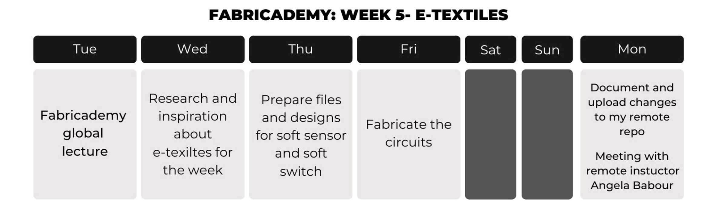
1. Weekly Documentation planning
2. E-textiles: Research and Inspiration
3. Circuit
I had experience with electronics and pcb milling thanks to Fab Academy, I milled, soldered and programmed many different pcbs, but I never explore the soft side of circuit making.

During the first part of this week, I looked for inspiration in other people's work with soft sensors ans circuit applied to fabrics. I find the amazing page of Kobakant, full of tutorials and example projects which were really useful this week. Their KOBAKANT DIY wearable technology documentation was a comprehensible and accessible reference resource for my week:

I want to explore how can we create beautiful looking circuits that integrates with the projects they are made for, and not just stick a weird looking square circuit. I found this paper speaker made by Jess Rowland. This project explores the technical, design, and aesthetic possibilities of 2-D, flexible audio speaker technology. I also showed me the possiblities of working with flexible copper tape.

I also found Clara Daguin's work. It is amazing and really inspiring, I saw a couple of her projects. Her BODY ELECTRIC project garment reveals what hides beneath the skin. Veins and sinuous networks become visible through optic fibres and intricate hand-work. Heart sensors capture the body’s pulse and make it visible to the eye in waves of light, emanating from the embroidery. I absoluty love it.

According to Gavin Wright in electronics, a circuit is a complete circular path that electricity flows through. A simple circuit consists of a current source, conductors and a load. The term circuit can be used in a general sense to refer to any fixed path that electricity, data or a signal can travel through.
According to Physical computing, There are a number of schematic building tools aimed at makers, each with their own tradeoffs.
Circuit.io. Has some very interesting auto-completion features, combines design+code, is purely a web app. No simulation support.
Fritzing. Provides both pictorial (“breadboard”) plus schematic representations. Was “industry standard” for many years but has struggled with fundraising and feature improvements of late.
Tinkercad Circuits. Allows you to design Arduino-based circuits, write code, and simulate. Does not provide schematic representations.
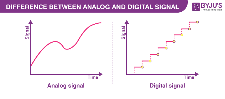
Analog and digital signals are used to transmit information, usually through electric signals. In both these technologies, the information, such as any audio or video, is transformed into electric signals.
The difference between analog and digital technologies is that in analog technology, information is translated into electric pulses of varying amplitude. In digital technology, translation of information is into binary format (zero or one) where each bit is representative of two distinct amplitudes.
Digital input is any input that can be considered either on (typically, HIGH or 5V) or off (typically, LOW or 0V). Simple, right? However, using digital input with microcontrollers can be confusing, at least at first.
Arduino Uno have 14 digital I/O pins that can be used either for input with digitalRead() or output with digitalWrite(), respectively
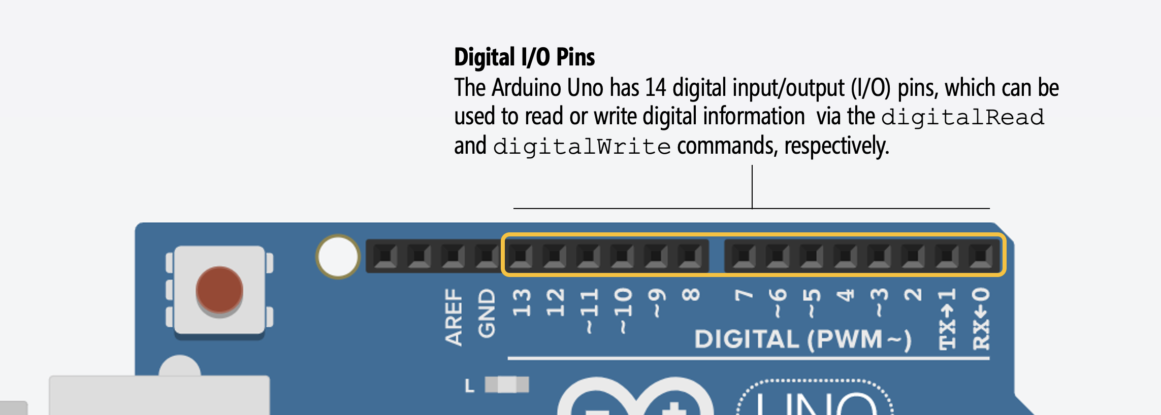
You can control any of these 14 digital I/O pins with three functions:
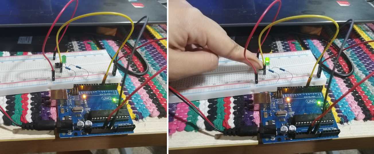
pinMode(int pin, int mode) configures a specified pin as either an INPUT or OUTPUT. For our buttons, we’ll be using INPUT—because a button is an input and not an output—and a variant of INPUT called INPUT_PULLUP.digitalRead(int pin) reads digital input from the specified pin, either HIGH or LOW. This is what we need to read the button’s state (either pressed or not pressed)digitalWrite(int pin, int value) writes digital output to the specified pin, either HIGH or LOW. This is not relevant to us here because we don’t write out data to a button.For my digital soft sensor I decide to make a simple button-based circuit that turns on a LED when the button (aka momentary switch) is pressed. Similar to the next example:
Using a button as a switch is simple to understand, a switch is an electrical device designed to interrupt the flow of electricity in a circuit. A switch can make or break an electrical connection. A switch can be either fully ON or fully OFF. In a fully ON condition, it creates a closed path between the source and load, so that the load can consume power (current) from the source. In a fully OFF condition, it open-circuits the path between the load and the source, so that no power is consumed by the load.
I'm using a four-legged tactile button for this circuit, at first it's confusing how this component works but I found a great page called physical computing that explains it.
I decide to use Thinkercad to quickly simulate my circuit. Then I made a test usign a breadboard. Using the serial monitor of Arduino IDE I read the digital signal adn everything worked well.
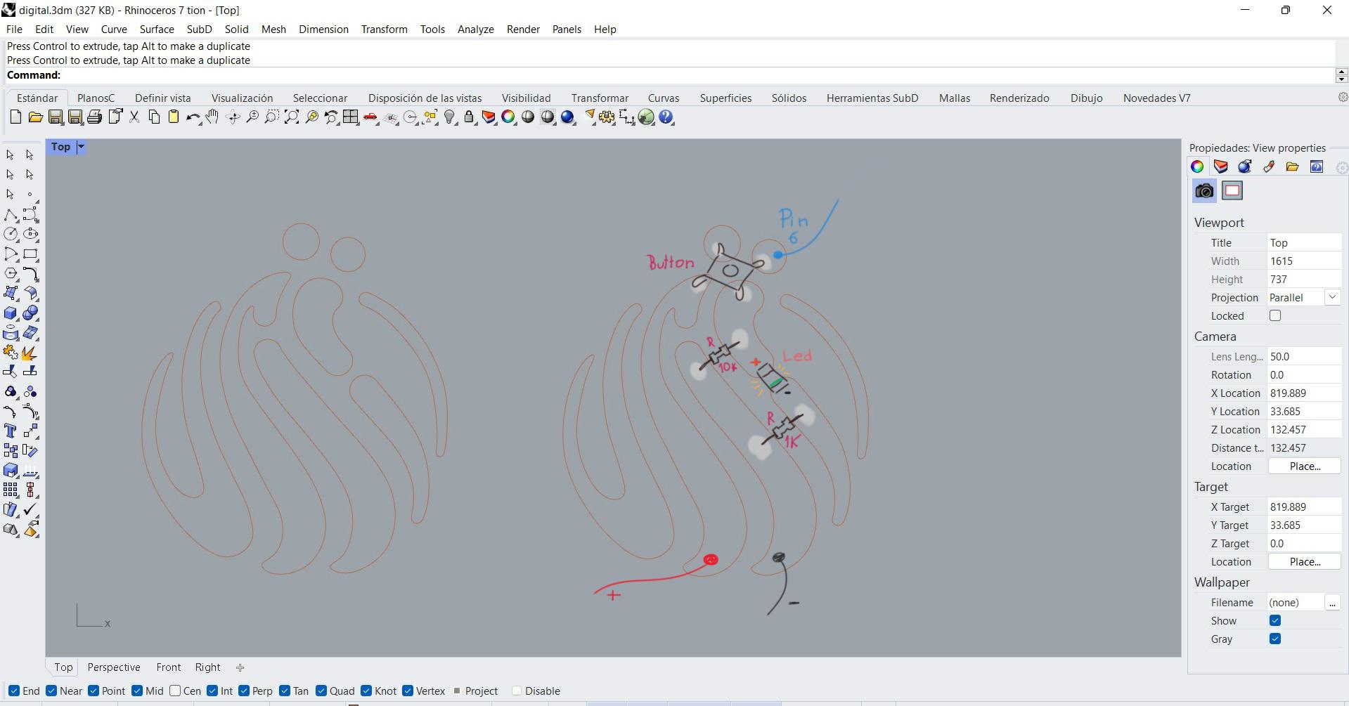
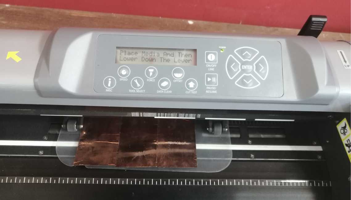
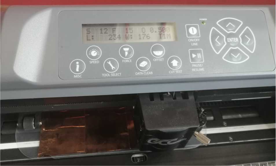
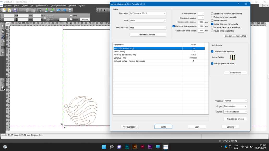
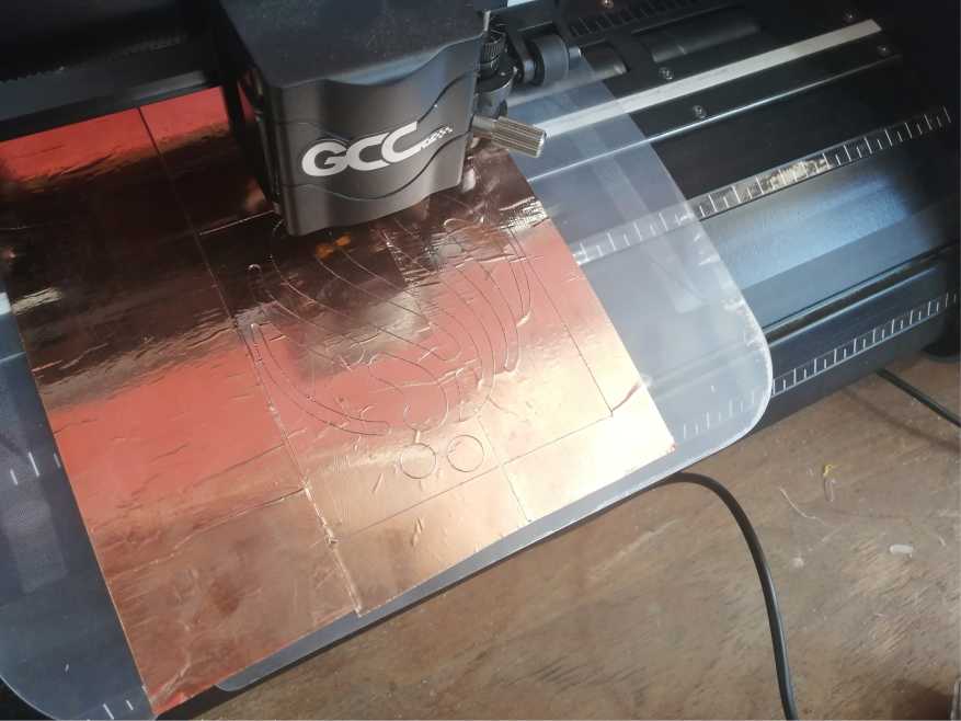
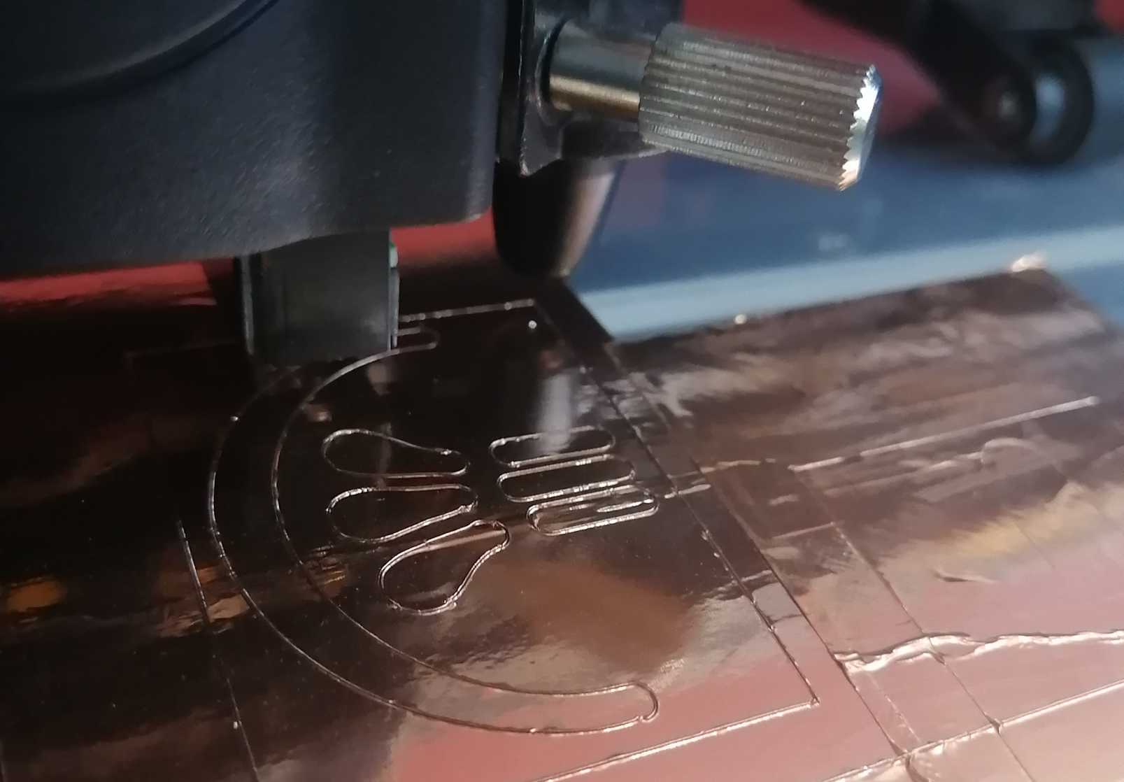
Once I got the electronic part figured out, I focused on the development of the fabric swatch. I design the copper paths in Rhinoceros and fabricated them using the vinyl cutter of our lab. Here's the process:
 |
|
|---|
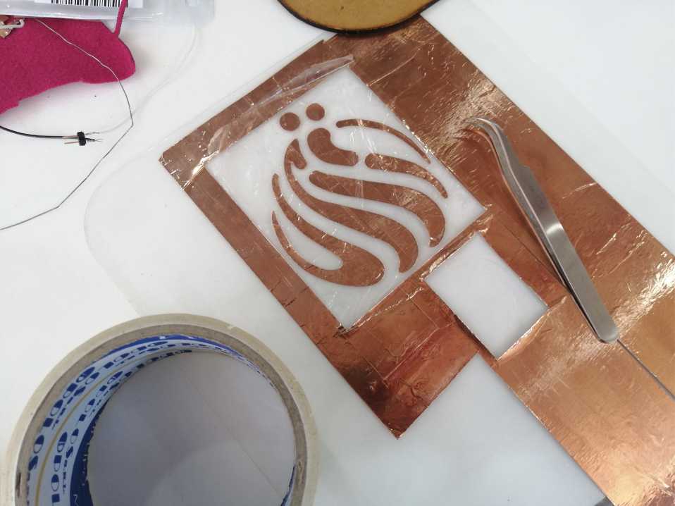
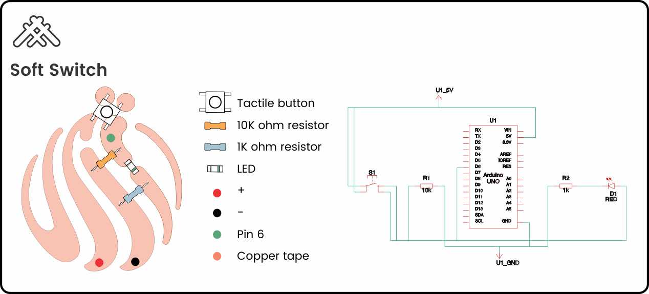
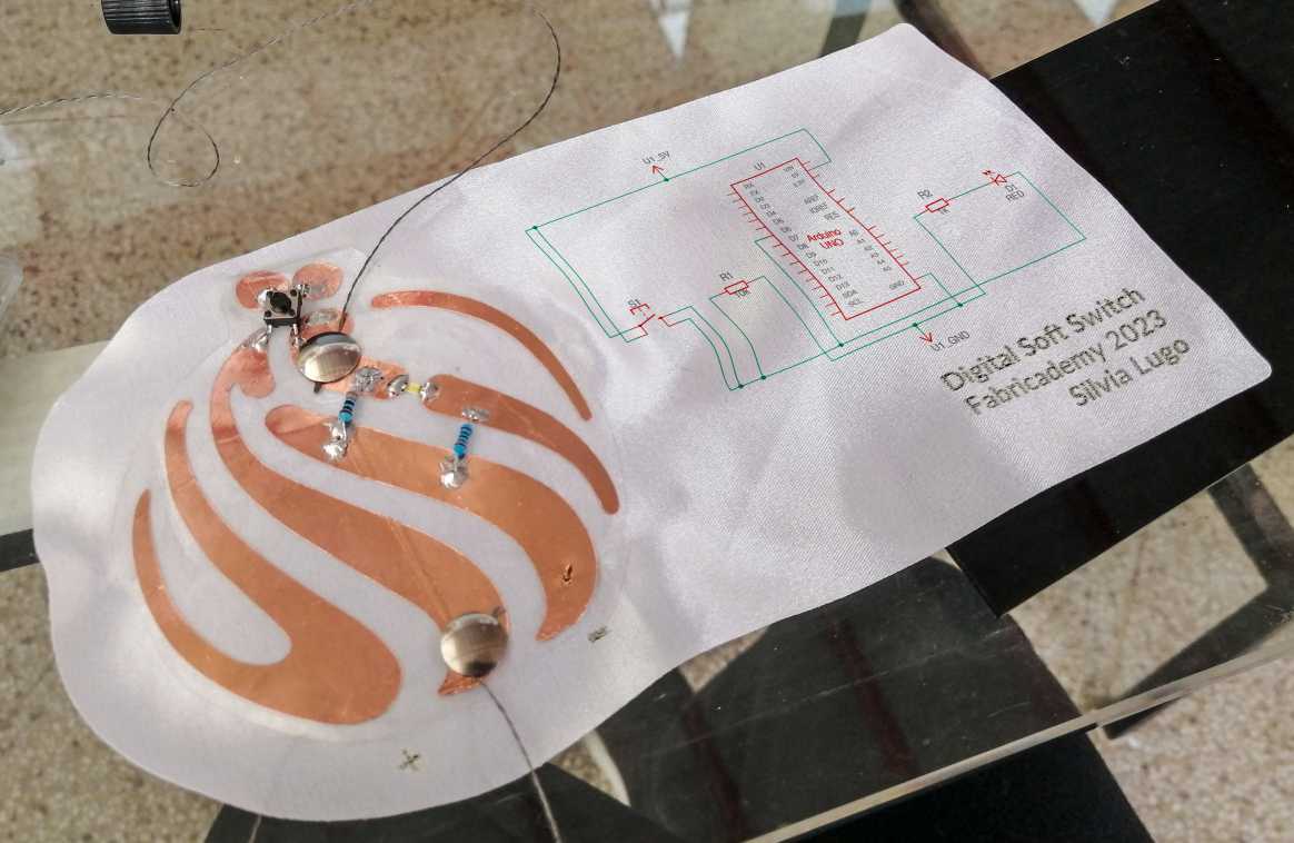
Once I placed the copper tape and solder my components, I tested the code and it worked!. Here you can check my results and how it reads the signal:
Soft switch de Silvia Lugo
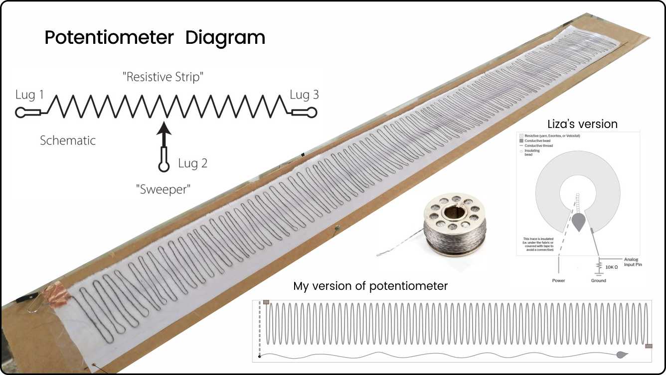
For my analog soft sensor I decide to make a potentiometer, which is a three-terminal resistor with a sliding or rotating contact that can be used to dynamically vary resistance.
At this point I had to improvise, because all the potentiometers that I found on the internet uses resistive fabrics, which at this time I didn't have. But I bought a conductive thread that has good resistance and would make the job. In order to suceed, it was important to understand how potentiometers work.
Potentiometers have three legs: the resistance between the outer two legs (Leg 1 and Leg 3) will not vary. For example, if you are using a 10kΩ potentiometer, then the resistance between Legs 1 and 3 will always be 10kΩ regardless of wiper position (Leg 2). If you’re using a 1kΩ resistor, then the resistance between Legs 1 and 3 will be 1kΩ, and so on.
The power of a potentiometer is in that middle leg (Leg 2) whose resistance varies depending on the potentiometer’s sliding or rotating contact (the wiper) position. It may help to think of a potentiometer as containing two interdependent resistors R1 and R2 that always sum to RTotal (where RTotal is the potentiometer’s total value like 1kΩ or 10kΩ). As you move the slider contact, R1’s resistance will increase as R2’s resistance decreases.There are two common ways to use a potentiometer: as a variable resistor or rheostat—where you only hook up two legs (the wiper leg and an outer leg)—and as a voltage divider.
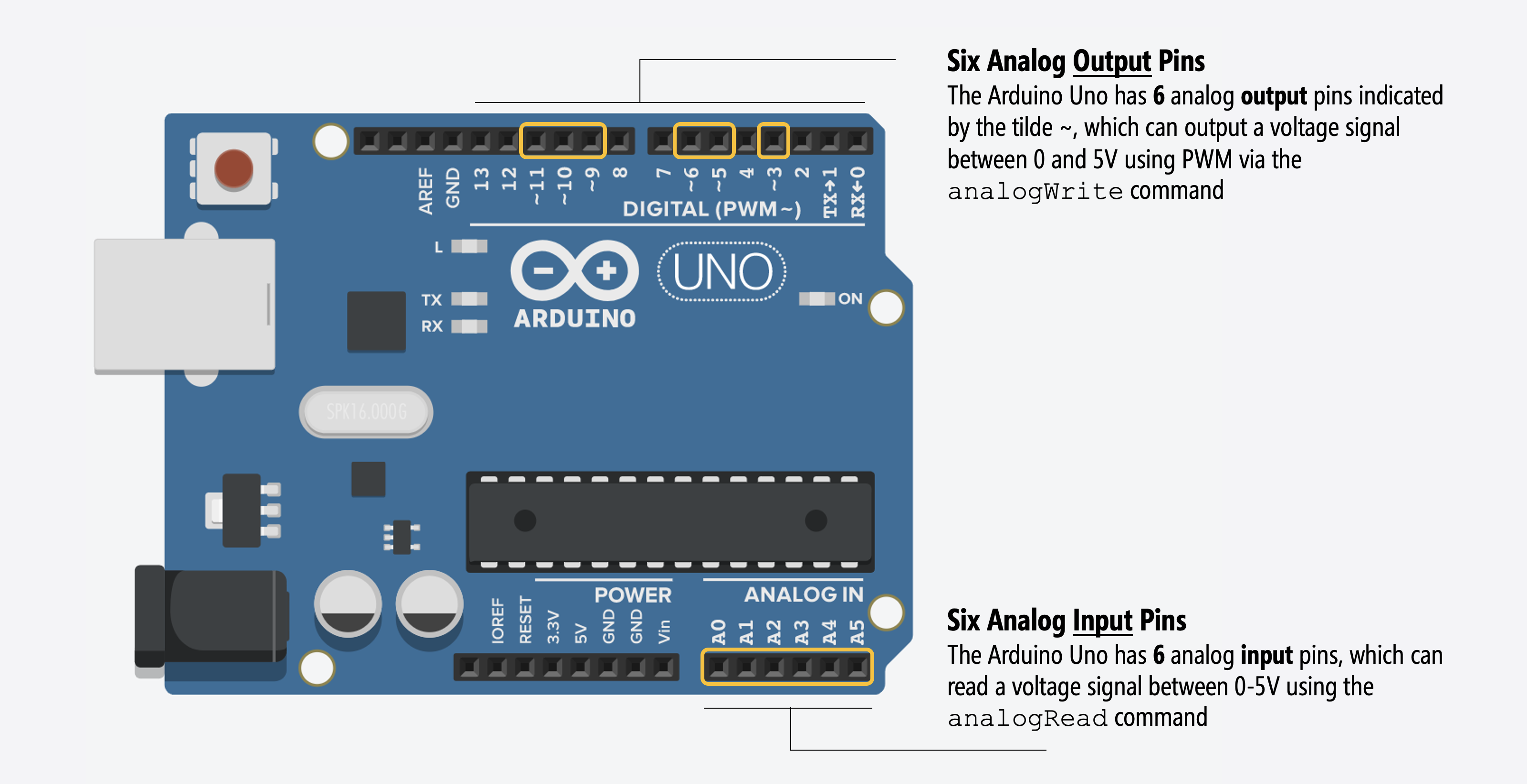
Arduino has analog output pins and analog input pins. For digital I/O, the input and output pins are the same and configurable to INPUT or OUTPUT using the pinMode command, the analog I/O pins are different! See the figure below:
To test my sensor with output I recreate the quick LED tester found in Liza Stark page. This simple ciruit is to plug right into the Arduino instead of having to hook LEDs up to a breadboard every time you want to test a sensor.
Here'es my final result:
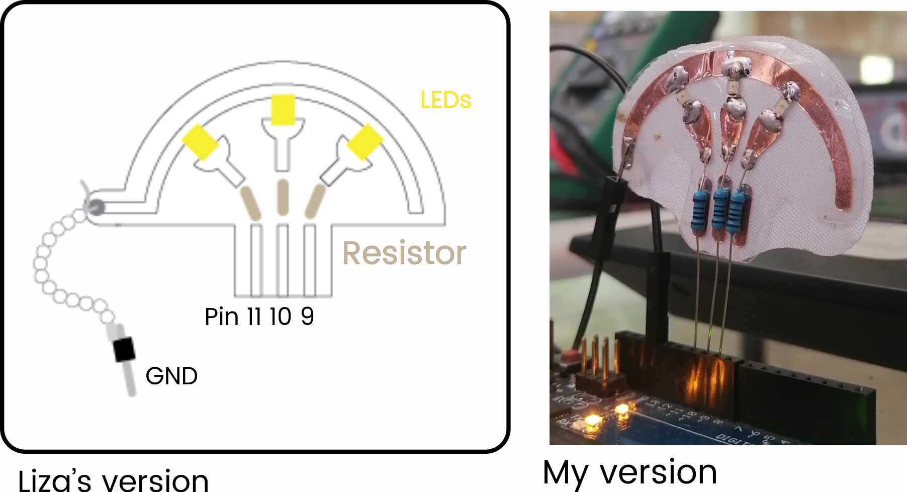
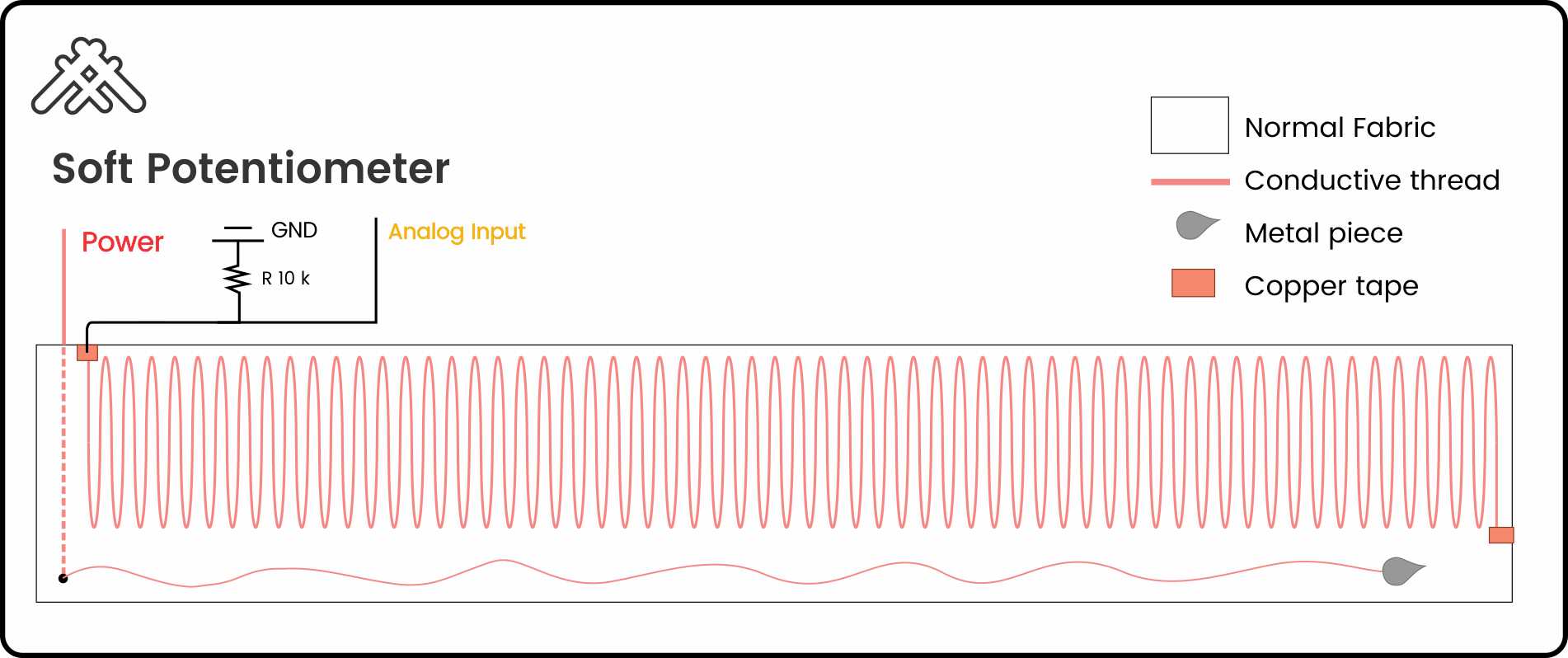
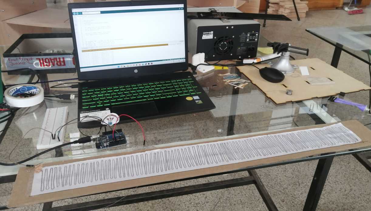
To build my potentiometer I follow the tutorial of Liza Stark about Soft Sensors. In her tutorials she uses resistive fabric, I didn't have that material, but I had conductive thread, after I measure the resistance of the thread I built a linear potentiometer stitching it in zigzag.
Industry Application of 3D Scanning