6. Computational Couture
Research & Ideation

Computational couture refers to a design approach in which computation is used as a generative tool to design textile systems, garments and surfaces whose form and behavior emerge from algorithms, parameters and material interaction. Rather than relying on traditional pattern-making alone, computational couture integrates digital modeling, simulation and fabrication to explore new relationships between body, maaterial and geometry.
Within this field, several fabrication and design techniques are commonly employed, each enabling different types of textile behavior and expression.
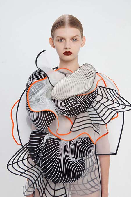
- BEHIND THE SCENES Hypnosis Collection by Iris Vanh Erpen irisvanherpen.com
Classification of Computational Couture Structures
Based on the research, computational couture techniques can be grouped into the following structural families, according to how geometry and fabrication define material behavior.
 Biolab examples computational couture structures by Carlos Roque e Carolina Delgado. Montage by Carlotta Premazzi
| Category | Description | Key Characteristics |
|---|---|---|
| 3D Printed Textile-like Structures | Textile-like systems generated through additive manufacturing, where flexibility and porosity are defined by geometry. | Non-woven meshes (gyroid) Quasi-woven fabrics Flexible TPU structures |
| Hinged and Expandable Tilings | Planar geometries designed to transform through rotation, unfolding or expansion. | Hinged tilings Expandable surfaces through cuts or joints Geometry as mechanical mechanism |
| Auxetic Structures | Geometry-driven systems exhibiting negative Poisson’s ratio, expanding in multiple directions under tension. | Re-entrant geometries Rotating and retractable surfaces Longitudinal expansion |
| 3D Printed Origami | Folding principles translated into 3D printed geometries that transform after fabrication. | Geometry-defined fold lines Post-print transformation |
| 3D Printing on Fabric Under Tension | Flexible polymers printed onto stretched textiles to generate self-forming surfaces once tension is released. | TPU printed on Lycra Self-forming surfaces Passive shape-memory behavior |
| Geometry-Driven Behavior | Structural behavior emerging primarily from geometric parameters rather than material properties. | Emergent form Material–parameter–force relationship |
Get Inspired — Student References & Practices
The following student projects and design practices were selected as references for computational couture, 3D printing on textiles, and geometry-driven fabrication approaches.
-
Echo Chen — Dekapede (independent research project)
Computational geometry applied to expandable and articulated textile-like structures.
https://echochen.design/04-Dekapede -
Jue Yang (Fabricademy 2023)
Experimental 3D printed textile systems combining parametric design and material behavior.
https://class.textile-academy.org/2023/jue-yang/assignments/week07/ -
Isobel Leonard (Fabricademy 2025)
Research-driven computational couture workflows integrating digital modeling and fabrication.
https://class.textile-academy.org/2025/isobel-leonard/assignments/week06/#research-ideation -
Alison Heryer (Fabricademy 2026)
Parametric surface generation and textile-inspired structures developed through digital tools.
https://class.textile-academy.org/2026/alison-heryer/assignments/week06/ -
Zahia Albakri (Fabricademy 2024 · CPF Makerspace)
Direct 3D printing on fabric experiments exploring adhesion, flexibility, and deformation.
https://class.textile-academy.org/2024/zahia-albakri/Projects/week07/#final-results -
Aslı Aydın Aksan (Fabricademy 2024 · TextileLab Amsterdam)
Investigation of TPU printing on textiles and geometry-driven surface behavior.
https://class.textile-academy.org/2024/asli-aksan/assignments/week07/#research-ideation
References & Inspiration
 Computational Couture Moodboard by Carlotta Premazzi
- Paper Vases by Romy Kühne pinterest
- Conductive Origami youfab
- SIKKA by Politecnico di Milano and istituto NUMEN, Expo Dubai 2020 winner 3dwasp
- Mj v5.1 hand gloves by DEONDlinkedin
- Enfold: A Pavilion to Quiet the Mind by DEOND design-milk
- 3d printed top [pinterest]
- Iris Vanh Erpen pinterest

- EDITORIAL Hypnosis Collection by Iris Vanh Erpenirisvanherpen.com
- 3D-printed elements into ruffled garments by Noa Raviv veniceclayartists
Tools
Software
Process and workflow
Based on the classification of computational couture structures, the practical exploration focused on two specific approaches: 3D printing on fabric under tension and geometry-driven auxetic structures printed in TPU. These case studies were selected to investigate how geometric parameters, material stiffness and fabrication conditions influence emergent textile behavior.
3D Printing on Fabric Under Tension
Forming a Flexible Lotus of Life Through TPU and Textile Interaction
 Lotus of Life Structure on Lycra
TPU 98A & Lycra Fabric Structure by Carlotta Premazzi, Biolab Lisbon.
Lotus of Life Structure on Lycra
TPU 98A & Lycra Fabric Structure by Carlotta Premazzi, Biolab Lisbon.
To create a flexible three-dimensional structure directly integrated with a textile substrate, the process starts with the design of a geometric pattern that can respond to tension and release. Unlike traditional molding, this technique relies on the interaction between elastic fabric and flexible filament to generate form.
The geometry was first designed as a 2D vector drawing in Adobe Illustrator, where radial symmetry and repeated circular elements were used to define the mandala structure. This approach allowed precise control over line weight, spacing, and proportions. The vector file was then exported as SVG/DXF and imported into Fusion 360.
In Fusion 360, the 2D geometry was converted into a parametric 3D model. A base module of approximately 200 × 200 mm was defined, and the pattern was generated using offset lines with a 2 mm spacing. The geometry was extruded to a thickness of 1 mm, balancing structural stability with flexibility, making it suitable for TPU printing on fabric.
The resulting digital model was exported as an STL file and prepared for fabrication using Ultimaker Cura. The material selected was TPU 98A, chosen for its elasticity and strong adhesion to textile substrates.
To ensure accurate deposition on fabric, printing parameters were carefully adjusted. The nozzle temperature was set to 235 °C, the bed temperature to 50 °C, and the fan was disabled. Printing speed was reduced compared to standard settings, and special attention was given to Z-axis recalibration to compensate for the thickness of the textile placed on the print bed.
For the physical setup, a 150 × 150 mm window of lycra fabric was stretched uniformly to approximately 40% tension and fixed directly onto the print bed. This tensioned setup prevents movement during printing and allows the TPU to bond directly with the fibers of the textile.
As the TPU is deposited, the structure becomes mechanically linked to the stretched fabric. Once printing is complete and the fabric tension is released, the elastic recovery of the textile induces controlled deformation and self-forming behavior in the printed geometry. This results in a flexible shell-like structure that emerges through material interaction rather than through a rigid mold.
This method demonstrates an alternative approach to form generation, where digital geometry, flexible materials, and physical forces collaborate to produce shape, merging additive manufacturing with textile behavior.
**Tool & Specs **
| Category | Item | Model / Type | Specifications |
|---|---|---|---|
| Material | Printing material | TPU 98A | Real Filament |
| Material | Substrate | Lycra | Elastic textile |
| 2D Design | Vector design software | Adobe Illustrator | Mandala geometry |
| 3D Modeling | Modeling software | Fusion 360 | Parametric 3D modeling |
| 3D Printing | 3D Printer | Ender 3 | Creality |
| 3D Printing | Slicing software | Ultimaker Cura | Print preparation |
| 3D Printing | Nozzle temperature | — | 235 °C |
| 3D Printing | Bed temperature | — | 50 °C |
| 3D Printing | Fan speed | — | 0% |
| 3D Printing | Printed object | Lotus of Life structure | TPU printed on lycra |
 Ender 3D Printer at Biolab Lisbon and Ender 3D Printer AI illustration by Carlotta Premazzi. (eden.art illustration from a real photography)
3D Printer — Main Components
| System | Components |
|---|---|
| Machine | Aluminum frame (V-slot profiles) Base frame Vertical Z-axis gantry Top frame / filament holder support Heated bed Build plate surface Bed springs / leveling knobs Y-axis carriage LCD display Control knob Main control board Power supply unit (PSU) Wiring harness SD card / USB interface |
| Motion | X-axis rail Y-axis rail Z-axis lead screw X-axis stepper motor Y-axis stepper motor Z-axis stepper motor V-wheels and rollers Timing belts (X and Y axis) Belt tensioners Endstop switches (X, Y, Z) |
| Extrusion | Extruder (Bowden type) Bowden tube (PTFE) Filament holder Filament guide Hotend Nozzle Heater block Heating cartridge Thermistor Heat break Heat sink Hotend cooling fan Part cooling fan |
3D Printing — Slicing Settings
When 3D printing directly onto fabric under tension, slicing parameters must be carefully adjusted to ensure adhesion, flexibility, and material integration without damaging the textile structure. The following settings were used to optimize TPU printing on stretched fabric.
| Setting | Value | What it means | Why it matters for printing on fabric |
|---|---|---|---|
| Material | TPU (flexible filament) | Elastic thermoplastic polyurethane | Allows the printed structure to stretch and move with the fabric |
| Layer height | 0.2–0.25 mm | Thickness of each printed layer | Slightly thicker layers improve bonding with textile fibers |
| Wall / Perimeters | 2–3 perimeters | Thickness of the printed structure | Balances flexibility and structural integrity |
| Top / Bottom layers | 3–4 layers | Solid top and bottom thickness | Keeps the pattern lightweight and flexible |
| Infill | 10–20% (Gyroid / Lines) | Internal density of the print | Maintains elasticity while reducing stiffness |
| Infill overlap | Increased (≈ 20–30%) | Overlap between infill and walls | Improves cohesion of flexible geometries |
| Print speed | 20–30 mm/s | Speed of the printing process | Slower speed improves adhesion to fabric and filament control |
| Nozzle temperature | 220–235 °C (TPU) | Extrusion temperature | Higher temperature helps TPU penetrate fabric fibers |
| Bed temperature | 40–60 °C | Heated bed temperature | Keeps fabric stable and prevents warping |
| Z-offset | Slightly reduced (−0.1 to −0.3 mm) | Distance between nozzle and bed | Encourages the molten TPU to bond with the textile |
| Fabric tension | Strong, evenly stretched | Mechanical tension applied to the fabric | Prevents fabric movement and deformation during printing |
| Supports | None | No support structures used | Avoids fabric damage and simplifies removal |
 Cura slicing setup for TPU printing on lycra fabric. Screenshot showing material, temperature, speed and cooling parameters.
Export & Machine Preparation — Lotus of Life
- The parametric model was exported from Fusion 360 as an STL file.
- The STL was sliced in Ultimaker Cura using TPU-specific settings for printing on fabric.
- A G-code file (.gcode) was generated from the slicing software.
- The G-code was transferred to the printer via SD card and executed on the Ender 3.
General Workflow
This workflow outlines the main steps followed to 3D print flexible TPU directly onto elastic textile substrates, highlighting the interaction between geometry, material, and tension.
1. Geometry Design
The process starts with the creation of a 2D vector pattern, later converted into a thin 3D geometry suitable for flexible filament printing.
2. Parametric Modeling
The 2D geometry is imported into a parametric modeling environment, where offsets and extrusion thickness are defined to balance flexibility and structural stability.
3. Slicing and Print Preparation
The model is sliced using TPU-specific settings, including reduced print speed, disabled cooling, and adjusted Z-offset to compensate for the textile thickness.
4. Textile Setup and Printing
The elastic fabric is evenly stretched and fixed onto the print bed, and TPU is extruded directly onto the tensioned textile to ensure adhesion and integration.
5. Tension Release and Evaluation
After printing, the fabric tension is released to activate deformation, and the resulting structure is evaluated in terms of adhesion, flexibility, and form behavior.
 3D Printing on Fabric Under Tension Test 1 (failed, too much tension, not dryed filament)
 3D Printing on Fabric Under Tension Test 2
⚠️ TPU & LYCRA
⚠️ TPU not adhere well
You are 3D printing TPU onto stretched lycra, but the printed lines do not adhere well and tend to peel off. This happens because: * Lycra has a smooth, low-adhesion surface, making it hard for TPU to stick. * The tension in the fabric can cause the TPU to lift once the tension changes. * The first layer may not be pressed enough into the fabric, so it sits on top rather than integrating with the fibers. * Fast printing or active cooling can solidify the TPU too quickly, reducing adhesion.
✅ Recommendations
- Fabric Preparation
- Keep the lycra slightly stretched, not overly tight, and secure it evenly with a frame or clips.
- Clean the fabric with isopropyl alcohol to remove oils and dust.
- Optionally, roughen the surface lightly with very fine sandpaper (800–1000 grit) to improve grip.
- Printer Settings
- Extruder temperature: 230–240 °C (or slightly higher if needed).
- Print bed: 50–60 °C if your printer allows it.
- First layer: lower the Z-offset slightly (0.05–0.1 mm) to press the TPU into the fabric fibers.
- Print speed: slow down to 15–20 mm/s for better adhesion.
- Cooling: keep fan off for the first few layers to avoid premature solidification.
- Adhesion Aids
- Apply a temporary fabric adhesive spray (e.g., 3M 75 or Odif 505) before printing.
- Consider a primer for synthetic fabrics to enhance TPU bonding.
- Pattern Considerations
- Use zig-zag or grid patterns instead of straight parallel lines, so the TPU can better accommodate the fabric’s stretch and reduce peeling.
⚠️ TPU Absorbs Moisture
TPU is hygroscopic, meaning it absorbs moisture from the air, which can cause: * Bubbling or popping during printing * Irregular extrusion and reduced adhesion * Rough or matte surface instead of smooth
✅ How to Manage TPU Moisture
- Dry the Filament Common methods:
- Oven at low temperature: 50–60 °C for 4–6 hours (check filament specs).
- Filament dryer (e.g., eSun, PrintDry, Sunlu).
- o not exceed 70 °C to avoid deforming the filament.
- Storage
- Store filament in an airtight bag with silica gel after each use.
- If possible, print inside a dry box to keep filament moisture-free.
- Environmental Control
- Avoid printing in high-humidity rooms (>50%), like bathrooms or kitchens.
- Consider using a sealed enclosure with a desiccant if the room is humid.
💡 Extra tip for TPU on lycra: Even with optimal Z-offset and adhesion aids, moist TPU will form bubbles and fail to bond with the fabric fibers, making the print detach easily. Dry filament is critical for successful printing on textiles.
➿ Lycra Tension for TPU Printing
- Lycra can stretch 100–200%, but for 3D printing TPU, only a small fraction of its elasticity should be used.
- Recommended stretch: 5–15% above the natural length.
- Example: Lycra 15 cm natural length → stretch to 16–17 cm.
- Avoid stretching beyond 20%, as TPU may lift or peel when the fabric relaxes.
- Keep the fabric flat and evenly secured with clips or a frame.
TPU hardness matters: * Soft TPU (95A) → lower tension (5–10%) * Hard TPU (98–98A) → can tolerate slightly higher tension (up to 15%)
💡 Key rule: Use the minimum tension needed to keep the fabric flat; too much stretch reduces adhesion.
Procedural Geometry — Blender Geometry Nodes
Geometry Nodes provide a procedural approach to modeling in Blender, where geometry is generated through node-based logic rather than manual editing.
By defining parameters and relationships between operations, complex forms can be built, modified, and reused efficiently.
This workflow introduces Geometry Nodes as a visual programming system suitable for generative design and digital fabrication.
From Rico Kanthatham'Tutorial
🛠 Tools & Setup
Software
- Blender 4.5.3
(here demonstrated using Blender 3.4 + macOS 10.14.6)
Add-ons - Node Wrangler
Hardware
- GPU recommended.
- 3-button mouse.
Setup Notes
- Geometry Nodes are applied as a modifier to an existing object
(usually the default cube)
🧠 Key Concepts
- Geometry Nodes work as a modifier
- Geometry Nodes are non-destructive
- Geometry is controlled parametrically
-
The workflow follows a clear data flow:
Input Geometry → Node Operations → Output Geometry
-
Node trees can be reused like recipes
- Complex forms emerge from simple rule-based systems
⌨ Essential Shortcuts
- SHIFT + A → Add node
- SHIFT + ALT + Click (Node Wrangler) → Connect node to output
- CTRL + Right Click + Drag → Cut connections
- SHIFT + Right Click + Drag → Insert node on wire
- F → Create frames (visual comments)
- Pin icon → Keep node tree visible

Preparing Blender Geometry Nodes by Carlotta Premazzi
[Geometry Nodes as add-on on Blender preferences; Open Geometry Nodes Editor and create a New one; Inicial CTRL + Right Click + Drag → Cut node connections; Ready screen for create]
Method 1 — Instancing on a Grid
- Instancing means placing copies of an object on a set of points generated by another geometry.
- This method is useful for patterns, arrays, modular systems, and textile-like structures.
 Instancing on a Grid, Blender Geometry Nodes by Carlotta Premazzi
1.1 Creating a Parametric Grid
- Add a Grid node
- Create parameters in the Group Input:
- Grid size
- Resolution
- Rename parameters clearly
- Define value ranges in the side panel (N)
- The grid is now fully controllable from the modifier panel.
1.2 Instancing Geometry on Points
- Typical setup:
- Grid → generates points
- Instance on Points
- Object Info → reference the object to duplicate
- Realize Instances → convert instances into real geometry
⚠️ For fabrication workflows, instances must be converted into real geometry using Realize Instances.
1.3 Realize Instances
- Add Realize Instances after Instance on Points
- Connect:
- Instance on Points → Realize Instances
- Realize Instances → Group Output
- This converts instanced geometry into real mesh data required for export and fabrication.
When to Use
- Required for exporting geometry (STL / OBJ / 3MF)
- Required for 3D printing and fabrication workflows
Method 2 — Noisy Generative Surfaces
- This technique is used to create organic and irregular surfaces, often inspired by natural systems.
 Noisy Generative Surfaces, Blender Geometry Nodes by Carlotta Premazzi
2.1 Mesh Distortion Using Noise
- Start with a Grid
- Add Set Position
- Use Noise Texture and Random Value
- Connect noise to vertex positions
- This introduces controlled variation across the surface.
2.2 Axis-Based Noise Control
- Use Combine XYZ
- Apply noise to:
- X / Y → horizontal distortion
- Z → height and relief
- This approach is ideal for:
- surface patterns
- material experiments
- 3D printable textures
Method 3 — Attractors & Repulsors
- This method creates interaction between geometries based on distance.
 Attractors & Repulsors in Blender Geometry Nodes, Premazzi Carlotta
Concept
- One object influences another by controlling:
- scale
- deformation
- vertical displacement
- The closer the objects are, the stronger the effect.
3.1 Basic Setup
- Object Info → reference the influencing geometry
- Geometry Proximity
- Map Range
- Connect to Scale or Position
- Limiting the effect to the Z-axis produces a field-like behavior.
Switching Between Attractor and Repulsor
💡 To invert the behavior:
- set From Min higher than From Max in the Map Range node
This simple inversion changes repulsion into attraction.
Exporting for Fabrication (3D Print)
- Before exporting:
- Ensure the final result is a Mesh
- Apply the Geometry Nodes modifier
- Go to File → Export → STL
- Enable Selection Only
- Export
⚠️ Geometry Nodes must be applied, or the exported file will be empty.
Auxetic Structure
 Auxetic structure by Carlotta Premazzi, printed in TPU 98A. Manual deformation test showing limited expansion due to hinge thickness and material stiffness.
This second experiment focused on the design and fabrication of an auxetic structure, aiming to investigate how geometric configuration influences expansion behavior when 3D printed in flexible material. The auxetic structure consists of compact circular units with hinge-like connections, producing controlled, geometry-driven expansion.
 Auxetic 2D drawing and his inspiration by Carlotta Premazzi
**Tool & Specs **
| Category | Item | Model / Type | Specifications |
|---|---|---|---|
| Material | Printing material | TPU 98A | Real Filament |
| 2D Design | Vector design software | Adobe Illustrator | Auxetic-structure-circle |
| 3D Modeling | Modeling software | Fusion 360 | Parametric 3D modeling |
| 3D Printing | 3D Printer | i3 MK3/S | |
| Original Prusa | |||
| 3D Printing | Slicing software | PrusaSlicer 2.9.3 | Print preparation |
| 3D Printing | Nozzle temperature | — | 210 °C |
| 3D Printing | Bed temperature | — | 50 °C |
| 3D Printing | Fan speed | — | 0% |
| 3D Printing | Printed object | Auxetic-structure-circle | TPU printed on print bed |
3D Printing — Slicing Settings
For the fabrication of the auxetic structure, slicing parameters were adjusted to preserve geometric accuracy, hinge flexibility, and controlled deformation behavior when printed in flexible TPU material. The following settings were used to optimize the printing of geometry-driven auxetic patterns.
| Setting | Value | What it means | Why it matters for auxetic structures |
|---|---|---|---|
| Material | TPU 98A (flexible filament) | Elastic thermoplastic polyurethane | Enables deformation and recovery of auxetic geometry |
| Layer height | 0.2 mm | Thickness of each printed layer | Ensures clean hinge definition and consistent geometry |
| Wall / Perimeters | 2–3 perimeters | Thickness of structural lines | Balances flexibility and structural continuity |
| Top / Bottom layers | 3–4 layers | Solid top and bottom thickness | Maintains structural stability without stiffening hinges |
| Infill | 10–20% (Lines / Gyroid) | Internal density of the print | Preserves elasticity while supporting deformation |
| Print speed | 25–35 mm/s | Speed of the printing process | Improves dimensional accuracy of small geometric features |
| Nozzle temperature | 210 °C (TPU) | Extrusion temperature | Provides stable flow and good layer adhesion |
| Bed temperature | 45–55 °C | Heated bed temperature | Improves bed adhesion for flexible filament |
| Cooling fan | 0% | Part cooling during printing | Prevents premature solidification and layer separation |
| Z-offset | Standard calibration | Distance between nozzle and bed | Ensures accurate layer stacking |
| Supports | None | No support structures used | Avoids interference with auxetic movement |
Export & Machine Preparation — Auxetic Structure
- The auxetic model was exported from Fusion 360 as an STL file.
- The STL was prepared in PrusaSlicer using flexible TPU settings.
- A G-code file (.gcode) was generated after slicing.
- The G-code was saved on SD card and printed directly on the Original Prusa i3 MK3/S.
Parametric Modeling
The auxetic pattern was developed using a parametric workflow in Fusion 360, based on a modular tile designed to exhibit lateral expansion under longitudinal stress. The base geometry was defined as a 200 × 200 mm tile.
The auxetic behavior was generated through re-entrant and hinged geometric elements, with parameters controlling unit size, spacing and connection thickness. Offset operations were applied to define structural continuity, and the geometry was extruded to a thickness of 1 mm to maintain flexibility while preserving printability in TPU.
Slicing and 3D Printing
The model was exported as an STL file and prepared for fabrication using PrusaSlicer software. The selected material was TPU 98A, chosen for its elastic properties and suitability for printing flexible, geometry-driven structures.
To improve print stability and reduce deformation, the travel speed was reduced to approximately 50% of the default settings. Since the structure was printed directly onto the print bed without any textile substrate, standard Z-axis calibration was applied, ensuring proper nozzle distance and consistent extrusion throughout the print.
Physical Setup
The print was performed directly on the printer bed without any textile substrate. The build plate was cleaned and prepared to ensure proper adhesion of the flexible TPU material during printing.
No additional fixation systems were required, as the structure relied solely on bed adhesion and material flexibility. This setup allowed the auxetic geometry to be fabricated as a self-supporting structure, enabling direct observation of its expansion behavior and mechanical response once removed from the print bed.
Results and Observations
The TPU material allowed a certain degree of flexibility; however, the overall deformation of the pattern remained limited.
When manually manipulated, the structure showed partial opening of the re-entrant units, but the expected multi-directional expansion was constrained. This suggests that the combination of unit scale, connection thickness and material stiffness limited the rotational freedom of the hinged elements.
3D Models
Fabrication files
- Download STL File – Lotus of Life (used for 3D printing on fabric)
- Download SVG Auxetic Structures Circles
- Download STL File – Auxetic Structures Circles (used for 3D printing)
🔗 References & Tutorials
3D Printing on Fabric & Direct-to-Textile Processes
-
Direct-to-Textile 3D Printing – Ganit Goldstein
https://www.youtube.com/watch?v=BdXBqfczzrI -
Stratasys and Dyloan – Taking Fashion Design into the Future
https://www.youtube.com/watch?v=Kx2j6pLDWo8 -
The Future of Fashion – Stratasys®
https://www.youtube.com/watch?v=WNagdCcJb3w -
5 Ways to 3D Print Fabric | Experimenting with 3D Printed Textiles – Sew Printed
https://www.youtube.com/watch?v=BW_l6PvyC3c
Experimental 3D Printed Textiles & Material Behavior
-
3D Printing on Fabric – Experimental Tests and Material Behavior
https://www.youtube.com/watch?v=oUdoEHYluiU -
3D Printing on Fabric – Adhesion and Flexibility Experiments
https://www.youtube.com/watch?v=qCOanCRQQJQ -
3D Printing on Textile Substrates – Process Overview
https://www.youtube.com/watch?v=WquJ7PEqYi8 -
Flexible Filaments on Fabric – TPU Printing Tests
https://www.youtube.com/watch?v=i3CKsuv0Sbk -
3D Printed Textile Structures – Pattern and Deformation Studies
https://www.youtube.com/watch?v=4oqf--GMNrA -
Hybrid Fabric–Plastic Structures Through 3D Printing
https://www.youtube.com/watch?v=GgJt6vIbiso -
3D Printing Directly on Fabric – Failure Modes and Improvements
https://www.youtube.com/watch?v=6MQSxgcn9i0 -
Textile-Based 3D Printing – Material Interaction and Results
https://www.youtube.com/watch?v=W1XlcKpVsIg
Designers, Research Practices & Video Series
-
Arantza Vilas — Computational and Textile-Based Design Practice
https://www.arantzavilas.com/ -
3D Printed Textiles – Research and Experimental Video Series
https://www.youtube.com/watch?v=7Liv--XSaCg&list=PLY1UnHZPnDCeXKWZJCkeGwFBmjQI9Bk4F&index=3
Auxetic Structures, Expandable Patterns & Geometry
-
Auxetic Structures and Materials – Materiability
https://materiability.com/portfolio/auxetics/ -
Auxetic Materials and Structures – ScienceDirect
https://www.sciencedirect.com/science/article/pii/0898122189901569 -
Expandable Tilings and Geometric Growth Patterns
https://laboeasd.wordpress.com/2017/10/22/expandible-tilings/ -
Two-Dimensional Grids, Patterns and Structural Meshes
http://www.plm.com.ar/academico/morfo0/gal17/tramas2d.htm -
Auxetic Behaviour in Structured Materials – Royal Society of Chemistry
https://pubs.rsc.org/en/content/articlelanding/2015/sm/c4sm01612b
Computational Couture & Digital Fabric Simulation
-
Fabricademy — Computational Couture with Blender
https://caramel-adjustment-1d3.notion.site/Fabricademy-Computational-Couture-with-Blender-1079bb27ac98807caaefc63cd9773348 -
VMOD — 3D Digital Fabrics and Texture Simulation
https://vmod.xyz/3d-digital-fabrics-texture
Academic and Scientific Research
- DefeXtiles: Leveraging 3D Printer Defects to Create Quasi-Textiles — MIT News, 2020
https://news.mit.edu/2020/defextiles-leveraging-3d-printer-defect-to-create-quasi-textiles-1020
Lecture on October 21st, 2025 Global Instructor: Julia Koerner Local Instructor: Carlos Roque - 3D Print on textiles tutorial, 23rd October 2025
Student checklist
- [ ] Document the concept, sketches, references also to artistic or scientific articles on 3D printing and parametric modeling
- [ ] Design a parametric model using Grasshopper3D or Blender (or alternative parametric software) and upload the 3Ddesign file + required parametric files
- [ ] Learn how to use a 3D printer and document the step-by-step process and settings
- [ ] Document the workflow for exporting your file and preparing the machine, Gcode and settings to be 3D printed
- [ ] Print your file and document the outcomes
- [ ] Upload your stl file
- [ ] Submit some of your swatches to the analog material library of your lab. Size 20cm x 20cm approx (extra credit)