9. Wearables
Research
We were shown a lot of amazing projects in the session, but I guess what stayed with me were all the ones that manipulated light or had light interact with material.
RUR : Torrent of Light

Image Credit : socialbodylab.com
RUR : Torrent of Light is a sci-fi play that uses wearable light-up props and costumes.
Claire Danes’ Fibre Optic Dress at the Met Gala
Claire Danes’ fibre optic dress by Zac Posen at the Met Gala, made of fabric woven from optic fibres and lit up by LEDs, powered by 30 batteries !
Embodisuit

Image Credit : rachelfreire.com
The Embodisuit is a project that reacts to data and signals, and brings them to the forefront by mapping them to different parts of the suit, and ergo, the body.
Boundless

Image Credit : Kay Wasil, kwasil.com
I loved Boundless for it LEDs certainly, but also for the chain-mail modular approach to the PCB itself. The series of LED grids are made of individual PCBs, linked together to conduct power and signals, and the PCBs themselves serve an aesthetic function, instead of being hidden behind enclosures or fabrics.
Movimiento
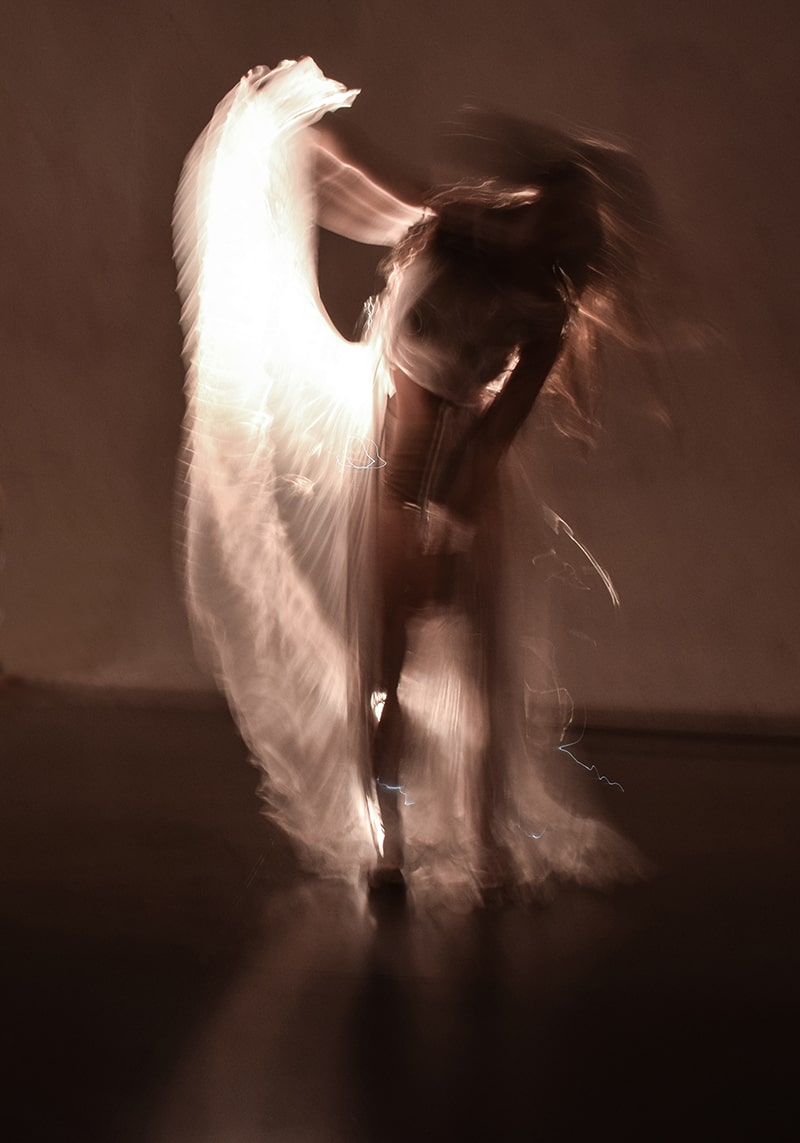
Image Credit : Maite Sosa Methol on the Textile Academy Archive
Movimiento was another project that deeply appealed to me, for the sheer potential of long exposure photography meeting the body in motion, in dance.
Beyond these projects, I decided to explore wearables and wearability through..
Circuit sculptures

Image Credits : from Pinterest
Accessories


Image Credits : from Pinterest
Brooches, Pins and Clipons, and adding them as accessories
Retro x SciFi

Image Credits : from Pinterest
And finally, how could I leave out the Neon - EL wire - retro-sci-fi effects from movies and video games like Tron, the Lion King, and others.
Tools
Electronics :
- Microcontroller : SEEED XIAO RP2040 | Arduino Uno
- Light output : LEDs, Electroluminescent Wire
- Power Controls : MOSFET IRF520 as a module
- LDR
- Resistors : 220 Ohm, 10k Ohm
- EL Wire USB Driver (5V to EL AC transfomer)
- Powerbank (5V USB output)
-
Jumpers (Male - Male, Male - Female)
-
Soldering Station | Soldering Iron
- Heat Shrink Tubing
- Cu Tape, 10 mm
Textile :
- Fabric
- Lasercutter
- Needle
- Thread
- Thread snips
- Scissors
Software :
- InkScape | CorelDraw
- Fusion360
- Arduino IDE
- Board manager repos and Libraries for XIAO RP2040
Documentation :
- Webcam
- Webcam stand
- P5.js sketch to superimpose live view with on screen display
- ShareX - screen recorder
Ideation
Based on this fascination with light effects, I had several ideas.
- A jacket back that showed off a constellation, using LEDS and EL wire
- Neopixel strip underneath the collar that cast light effects across the back and front of the body
- A scarf with a line of light - Neopixel strip or EL wire - running it's length and controlled light patterns running on it. This would make for great long exposures as well as warm glows for portrait photography, etc
- Using magnets and coils to attract and repel each other, embedded in butterfly wings that then effectively flutter based on the coil current, controlled by a microcontroller
- Firefly pins or brooches that had LEDs underneath and emitted a glow controlled by sensor inputs or timing logic


Concept
I went ahead with my first idea. I detailed it out in terms of story as well as function. I did not want to use any of the usual Zodiac signs, but instead chose a constellation and a story that I had loved since childhood. The story had always caught my fancy, and as an occasional star-gazer, I knew my way around the summer sky enough to also be able to spot and photograph the constellations.
Story
The constellation Cygnus, the Swan, alongwith the stars Vega and Altair. The story goes that Vega and Altair, a princess and a shepherd, were lovers separated and banished to opposite sides of the heavenly river, the Milky Way. However, a flock of swans took pity on them. So one night a year, the flock of swans form a bridge of wings, to allow them to cross the river and meet.


Image Credits : NoirLab.edu, Starwalk.space, AstroBackyard.com
The Build
Functionally, this would be done as a patch for a jacket, to be attached by velcro. This makes the patch removable, allowing for easy repairs, tweaks or coding updates, as well as makes the rest of the jacket washable without concern for the electronics.
The EL wire defines the constellation while the LEDs mark the stars. An LDR under the collar turns on the whole thing when the collar is folded down and covers the LDR.
An Arduino Uno, via a MOSFET controls the EL wire power source, while the LEDs are directly controlled by the Uno. An initial version had everything fade simultaneously, but giving each LED and individual fade or blink looks better.
The LDR provides input data to the Uno.
If the LDR is exposed all the time, the code logic can be to turn everything on when ambient light goes below a certain threshold. However, it is more interesting if the LDR is under the collar, and the act of wearing the jacket and flipping the collar in place, thereby covering up the LDR, and using that as the input/threshold condition to turn on the lights.
Power requirements
The entire project can be powered off a USB powerbank :
- An Arduino Uno or a XIAO RP2040 use the USB 5V input
- The EL wire uses a 5V input to the EL wire transformer/driver
Each LED needs a 0.02 A supply, and since there is only 1 LED per pin, this is fine for the 0.02 A continuous-use limit and certainly for the 0.04 A regular use limit of the Arduino pins.
Process
Lasercutting the fabric

- I traced the constellation and stars as a vector drawing and exported that as an SVG.
- I measured the back of the jacket and created the patch as a sketch in Fusion360.
-
Then I imported and positioned the SVG in Fusion

-
The points of the constellation would have holes for LEDs. I drew 30 mm circles around each point to derive the EL wire threading holes where the constellation path intersected the circle, through which the EL wire could dive under the fabric and emerge ahead of the LED
- EL wire pathway under and over the fabric
- Final lasercutting drawing with LED and EL wire holes
Electronics
I prepped the LEDs, tested the EL wires and power sources, and began the slow painstaking task of attaching each LED, threading the EL wire through the holes, and assembling everything.
1. EL wire tests


2. LEDs prepped
Attached resistors and heat shrink tubing to prevent shorts, legs curled to be stitched


3. Fabric lasercut, EL wire woven through it, LEDs added


The EL wire I had had an extended flat edge, so I cut slits into it exactly where it emerged from a hole, so the slit would lock against the fabric edge in the hole. The EL wire was also stitched in place at all critical points.
4. Tapes, Stitches, Jumpers, Solder - the conductive pathways of the circuit


The arduino and mosfet modules were stitched in place. Jumpers were clipped to have header pins on one end and bare wire on the other. The pins connected to the Arduino headers, while the bare ends were soldered to the Cu tape pathways leading to the respective LEDs.
5. Final Assembly - Back and controller detail


Coding
The coding was relatively simple - after a point.
Setup and library installations for the XIAO can be found on my FabAcademy page here since I already had them in place.
Pin diagram for the XIAO RP2040
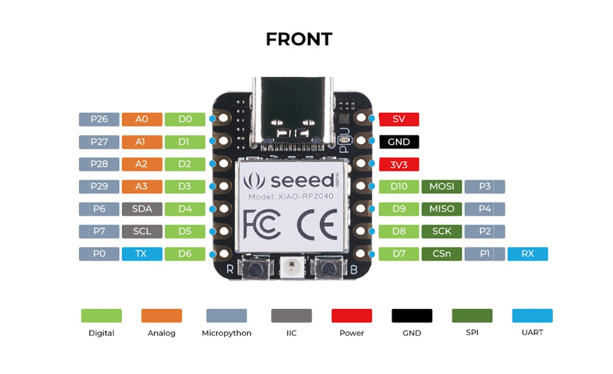
Initially I had planned on using a XIAO RP2040. However, the 3.3 V operating voltage seemed not to be enough to trigger my IRF520 Mosfet module.
So I switched to the Uno. In any case, I needed more pins as well.
Therefore, just to be sure, I initially tested the mosfet on a 12 V DC fan before trying it on the EL wire power supply.
MOSFET test
// IRF520 MOSFET Driver Module Test – Arduino UNO
// Toggles the MOSFET every 3 seconds and reports over Serial

const int mosfetPin = 9;   // Connect this to SIG on the MOSFET module
const unsigned long interval = 3000; // 3 seconds
bool mosfetState = false;

void setup() {
  Serial.begin(9600);
  pinMode(mosfetPin, OUTPUT);
  digitalWrite(mosfetPin, LOW);  // Start OFF
  Serial.println("System started - MOSFET OFF");
}

void loop() {
  mosfetState = !mosfetState;          // Flip state
  digitalWrite(mosfetPin, mosfetState);

  if (mosfetState) {
    Serial.println("MOSFET ON");
  } else {
    Serial.println("MOSFET OFF");
  }

  delay(interval);
}
Once the Mosfet was tested, and since time was of the essence, I used ChatGPT to iterate quickly and generate code that triggered the MOSFET as well as the 12 LEDs randomly
Connections
Arduino to Mosfet Module
Pin 1 - MOSFET Signal
5V - Vcc
Gnd - Gnd
Mosfet module
V+ - EL Wire Power supply V+
V- - EL Wire Power supply Gnd
Vin - Component Vin
Vout - Component Vout/Gnd
Arduino Uno
Pin 2 - 220 Ohm resistor - LED - Ground
Pin 3 - 220 Ohm resistor - LED - Ground
.
.
Pin 13 - 220 Ohm resistor - LED - Ground
Pin 5V - LDR - A0 - 10k Ohm resistor - Ground
Final Code - LEDs randomized
// MOSFET on Pin 1 toggles 1s ON / 1s OFF
// LEDs on pins 2–13 twinkle randomly (1–3s ON, 1–3s OFF)

const int mosfetPin = 1;
const int firstLedPin = 2;
const int lastLedPin  = 13;

unsigned long mosfetTimer = 0;
bool mosfetState = false;
const unsigned long mosfetInterval = 1000; // 1 second

// For each LED, track timing and state
unsigned long ledTimers[14];   // index by pin number, ignore 0–1
bool ledStates[14];
unsigned long ledIntervals[14];

void setup() {
  Serial.begin(9600);

  // MOSFET pin
  pinMode(mosfetPin, OUTPUT);
  digitalWrite(mosfetPin, LOW);

  // LED pins
  for (int pin = firstLedPin; pin <= lastLedPin; pin++) {
    pinMode(pin, OUTPUT);
    ledStates[pin] = false;
    digitalWrite(pin, LOW);
    ledIntervals[pin] = random(1000, 3000);
    ledTimers[pin] = millis();
  }

  randomSeed(analogRead(0)); // improve randomness
  Serial.println("System started");
}

void loop() {
  unsigned long now = millis();

  // ---- MOSFET toggling (pin 1) ----
  if (now - mosfetTimer >= mosfetInterval) {
    mosfetTimer = now;
    mosfetState = !mosfetState;
    digitalWrite(mosfetPin, mosfetState);
    Serial.println(mosfetState ? "MOSFET ON" : "MOSFET OFF");
  }

  // ---- LED twinkling (pins 2–13) ----
  for (int pin = firstLedPin; pin <= lastLedPin; pin++) {
    if (now - ledTimers[pin] >= ledIntervals[pin]) {
      ledTimers[pin] = now;
      ledStates[pin] = !ledStates[pin];
      digitalWrite(pin, ledStates[pin]);

      // choose next random interval (1000 to 3000ms)
      ledIntervals[pin] = random(1000, 3000);
    }
  }
}
Final with LDR input as Threshold
// MOSFET on Pin 1 toggles 1s ON / 1s OFF
// LEDs on pins 2–13 twinkle randomly (1–3s ON, 1–3s OFF)
// LDR input on AO

const int mosfetPin = 1;
const int firstLedPin = 2;
const int lastLedPin = 13;
const int LDRPin = A0;

unsigned long mosfetTimer = 0;
bool mosfetState = false;
const unsigned long mosfetInterval = 1000;  // 1 second

// For each LED, track timing and state
unsigned long ledTimers[14];  // index by pin number, ignore 0–1
bool ledStates[14];
unsigned long ledIntervals[14];

void setup() {
  Serial.begin(9600);

  // MOSFET pin
  pinMode(mosfetPin, OUTPUT);
  digitalWrite(mosfetPin, LOW);

  // LED pins
  for (int pin = firstLedPin; pin <= lastLedPin; pin++) {
    pinMode(pin, OUTPUT);
    ledStates[pin] = false;
    digitalWrite(pin, LOW);
    ledIntervals[pin] = random(1000, 3000);
    ledTimers[pin] = millis();
  }

  //LDR pin
  pinMode(LDRPin, INPUT);


  randomSeed(analogRead(0));  // improve randomness
  Serial.println("System started");
}

void loop() {
  unsigned long now = millis();
  //LDR checking condition
  int ldr = analogRead(LDRPin);
  if (ldr < 200) {


    // ---- MOSFET toggling (pin 1) ----
    if (now - mosfetTimer >= mosfetInterval) {
      mosfetTimer = now;
      mosfetState = !mosfetState;
      digitalWrite(mosfetPin, mosfetState);
      Serial.println(mosfetState ? "MOSFET ON" : "MOSFET OFF");
    }

    // ---- LED twinkling (pins 2–13) ----
    for (int pin = firstLedPin; pin <= lastLedPin; pin++) {
      if (now - ledTimers[pin] >= ledIntervals[pin]) {
        ledTimers[pin] = now;
        ledStates[pin] = !ledStates[pin];
        digitalWrite(pin, ledStates[pin]);

        // choose next random interval (1000 to 3000ms)
        ledIntervals[pin] = random(1000, 3000);
      }
    }
  }
}
Final
Backside, working
This is running an earlier version of the code where the LEDs were not randomized.
Frontside, final Later version with randomized LEDs
Cygnus, Vega and Altair
Starcrossed lovers in the Summer Sky
Reflections
This was simultaneously a great build and a flawed one.
On the one hand,
- I wanted to press-fit metal aglets in the LED holes to stop future fraying of the fabric, but realised only too late that I could not reach the holes in the interior of the fabric with my press punch
- I had a lot of issues with the MOSFET and power control of the EL wire,
- The EL wire available wasn't round but had a flat edge - this helped since I could cut slits into the edge to slot it on the fabric edge, but it was also proving to be very difficult to twist or bend compared to a simple round section. Eventually, I left large loops hidden below the surface wherever sharp turns were required.
- Cu tape isn't the best in the long term for resilience
- My solder/soldering iron was also acting up when I changed to what I suspect was a lower lead content solder, resulting in annoying solder mush
On the other hand,
- I finally got to use EL wire in a project
- I love the story so I was happy to execute the concept !
- It boiled down to multiple days of gathering materials and planning and lasercutting, and then a long 5-6 hour stretch of time where I just went at the final assembly, wiring, coding, etc in a near-flow state, partly frustrated but also unable to give up !
- Compared to my E-textile project where I used conductive thread, the Cu tape made things SO easy ! I had not allowed myself to use Cu tape exactly because it's not reliable in the long term, but I think it's great for a certain level of prototyping.
All in all, a fun project.
Files
Cutting Pattern Fusion file
Cutting Pattern DXF
Credits and Acknowledgements
Image Credits : All credits mine unless mentioned otherwise.