Introduction
I had a lot of trouble this week, especially because I have a tendency to start with complicated things, and then make mistakes and learn form my mistakes. In electronics, there are so many different mistakes possible that I really struggled to solve anything. In most cases, I solved my problems by going back to the basics (after hours and hours of trying the complicated version. Did I tell you? I'm really stubborn.) At first, I played with the Arduino uno and the examples included in the program. I blinked a led, made sond from a little speaker, tested different resistors to see the effects ont the led. I made a parallel circuit and a series circut on the bread board to see how the lights would spread the energy.
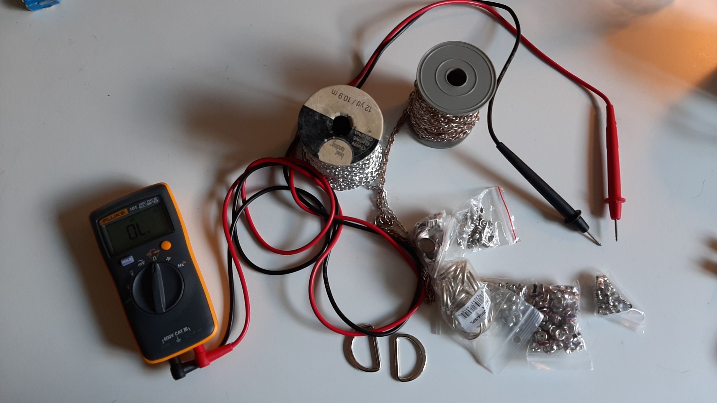
I had major problems when I tried to fade an Led. I learn the difference between a normal digital pin and a PWM digital pin. Since a normal digital pin can only work with zeros and ones, the light did not fade, it only blinked. I only had to change to a PWM digital pin and the problem was solved. I learned to use a multimeter, mesuring the voltage and mesuring the resistance. Once I was sure I undersand at least the basics of electronics I started doing some more important tests with sotf materials.
I mesured the resistance of every material, every thread end tested some snaps and buttons I had at home. A lot of my metalic beads were very conductives, and I didn't have any metalic zipper that was conductive enough. None of my beautiful chains were conductives!
Tests
Getting to know the materials
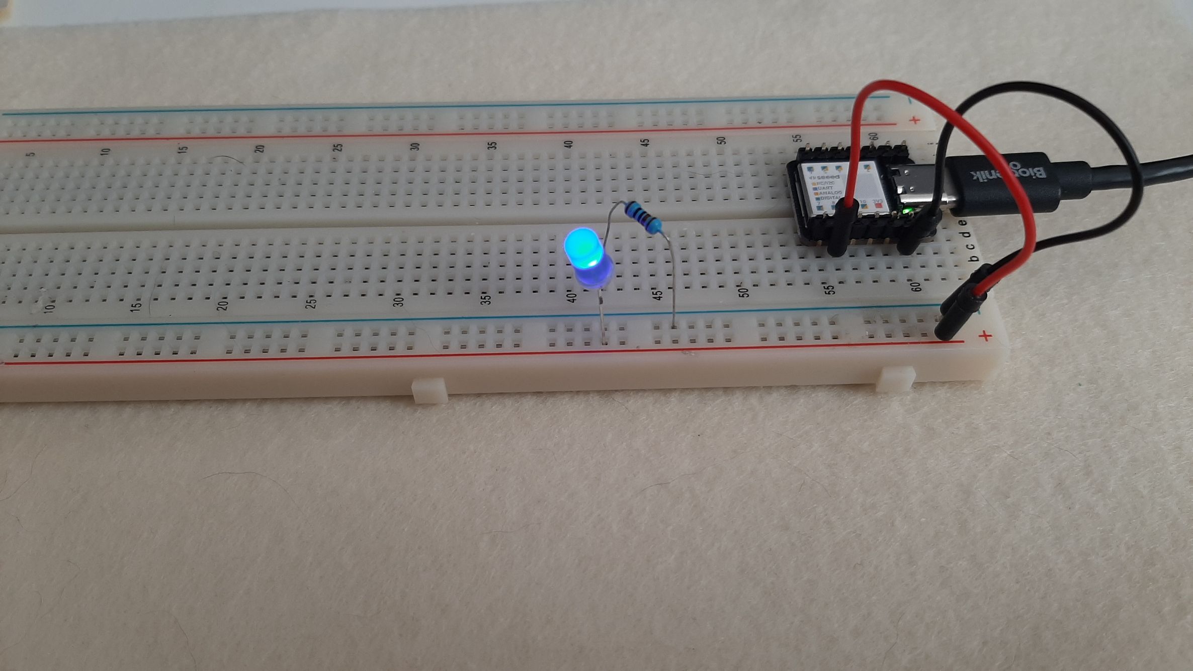
My first test was with this wonderful foam I hoped to use for a pressure sensor. The foam had a big resistance, so I put 7 volts to be sure to see the led light up. It was simply to visualise the effect of the resistance on the led. When I pressed it hard enough, I was reducing the resistance, and by doing so augmenting the intensity of the light.
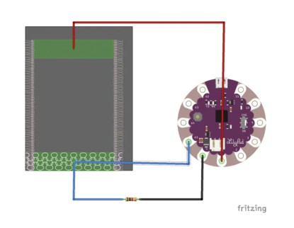 I took everything and pinned everything to a breadboard. I was so lost, but I had a bit of help. I wanted to do something out of the foam, something that would change state depending if it was pressed or not. I learn that in my case, I would need to do a Capacitive sensor. Capacitive sensor also work with PWM digital pins, so I had to be careful wich pin I choose as an output. I used an exemple code from arduino and placed my cables according to these instructions.
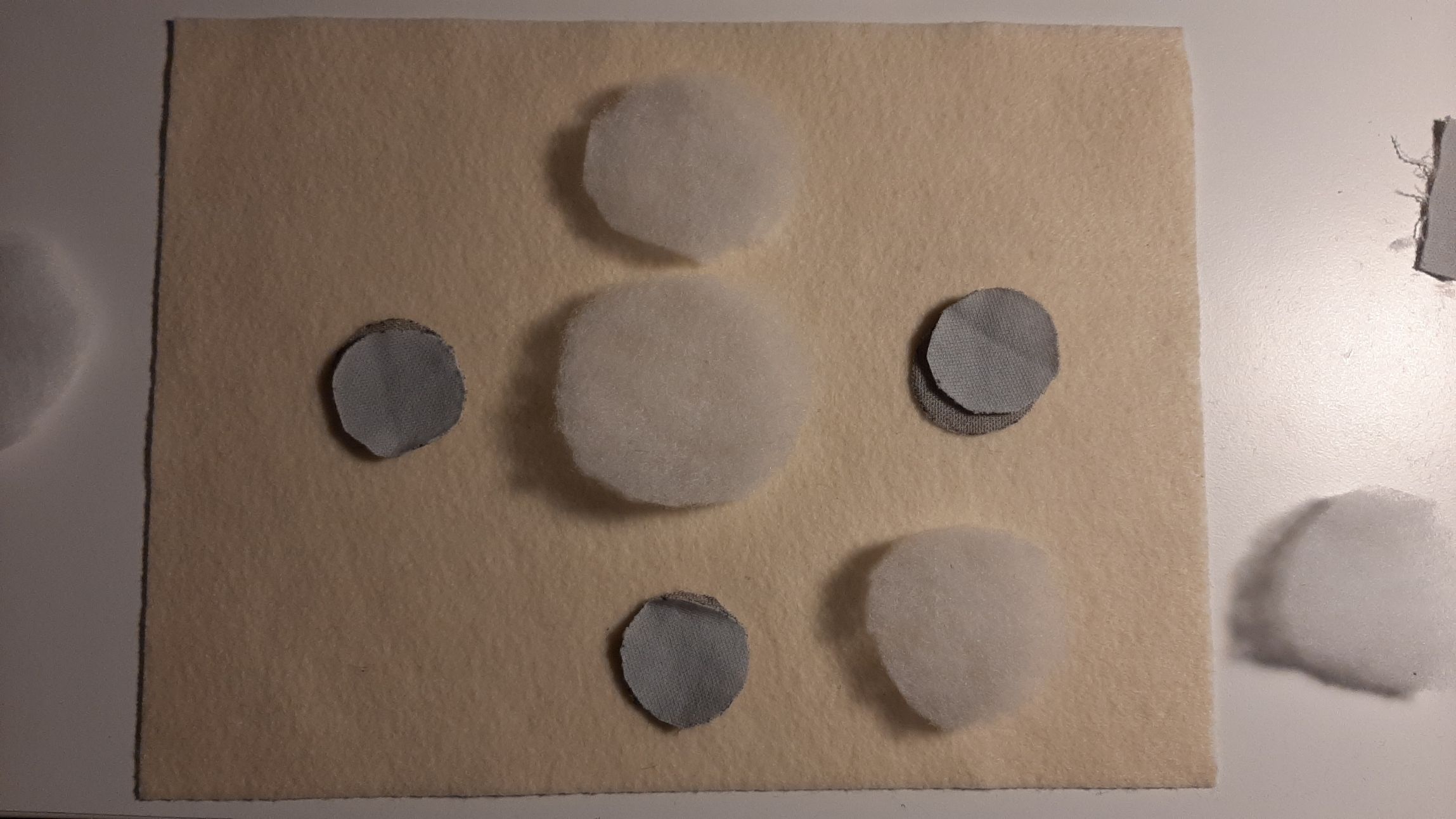
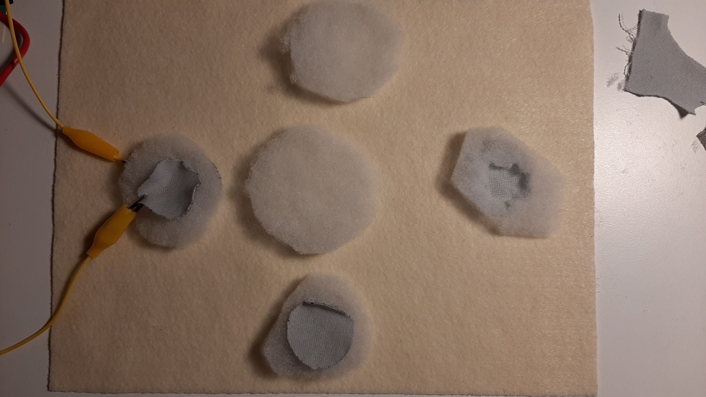
IT WORKED!! The input printed in the arduino serial monitor. The numbers got higher the more pression I put on the material. It could even sense when I got closer. I tried different materials and the all reacted differently. On the left, this foam was very stiff and could sense my had at about one inch from it. it reached about 2500 when I pressed on it. The other foam was much more flexible, and had more trouble sensing the pression. I had to fold it in half to reach higher numbers. But still, every material I tried had a big enough difference for me to program a reaction of the led.
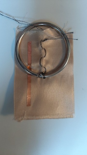 I found this conductive ring and I though I could do an analog read from it. Since the ring was not closed, I linked one end of my circuit to one end of the ring, and the other one to a set of conductive beads. My intention was to read different voltages depending on where the bead would touch. BUT IT NEVER WORKED! at least not in the way I intended. The resistance in the ring was so low that the arduino didn't see any difference.
With the button example from arduino and a bit of help, I was still able to program a simple button out of it. All my threads were sewn in the seam allowance, and hidden inside the sample. To connect it to the arduino, I simply made sure my knot at each end would show on the outside of the sample.
I tried to do a zig zag stitch with conductive thread, to see if the resistance would change. Unfortunatly, there was a little or no change at all.
Here is a velostat sheet, between two layers of conductive coil tape. The change of resistance is very visible, you can see it if you look at the led light intensity.
I then played with the ardino and codes with this paper speaker. I will talk more about that during the wearable week, but for now, I am proud I was able to make it work.
Analog Read
Pressure Sensor
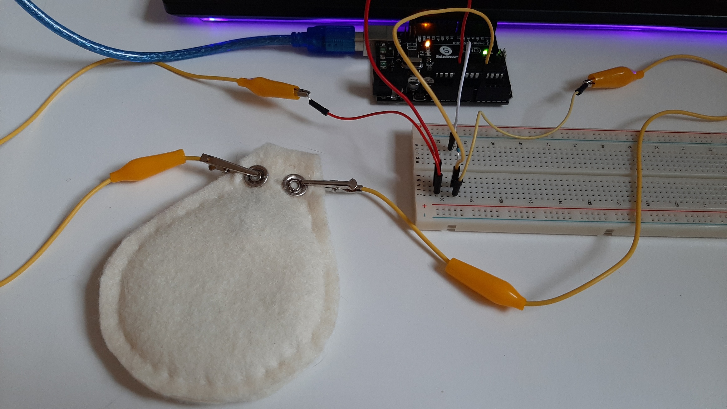
 I first made this sample completely independent. I simply connected a 3.3v battery and a led to the circuit, once again to see the effect of the resistance change. From there, I adapted the circuit to be connected to an arduino. I used a tutorial from Project Hub. Instead of using a bought pressure sensor, I used mine. It took me a couple of tries before getting a circuit that works. My pad is made of this conductive foam, sandwiched between two layers of conductive fabric. the foam is a tiny bit bigger than the conductive fabric, to make sure they don't touch. Each swatch of conductive fabric is connected to one snap. After sewing everything, I realised that a contact wasn't good... A loose knot maybe? I started over again and double checked the tension of my knots.
Once my pressure pad was done and worked (I cheked with the multimeter), I connected it to the breadboard. I recreated about the same circuit than in the tutrial, using a very small resistance. The code from the example was also usable: it was adapted to one particuliar pressure sensor, so it can give a real weight, and the code is also created to have 3 leds, reacting depending on the weight applied. I could work from that and adapt it to my own pressure pad, but for this example, I will simplify the code the more I can. Here is the simplest form of code, where you can see values representing the pressure on the pad.
int pressureAnalogPin = 0; //pin where our pressure pad is located.
int pressureReading; //variable for storing our reading


void setup(void) {
  Serial.begin(9600);
}

void loop(void) {
  pressureReading = analogRead(pressureAnalogPin);
  Serial.print("Pressure Pad Reading = ");
Serial.println(pressureReading);

  delay(1000);
}
Digital Read
This little project is ment to be a game, in which the player can control the intensity of each color. Each of the tree button controls either Red, Green or Blue, and pressing on a button augments the color's intensity. At least it was the idea! If for this week I can create the physical soft circuit, I would be satisfied!
I will use the basic fabric button theory for this prototype. They are simple; two layers of conductive fabric are kept apart from one another with a light foam. When the button is pressed, there is a contact, and electricity will flow. I made holes in the foam, in order to allow the contact to be made. Each button is connected to it's own pin on the seeeduino, in order to get informations from each of them individually.
The neopixel led's description is here. I had to solder conductive cables to them, since it was impossible to solder the conductive thread for sewing directly to the component. I will mostly focus my attention on the buttons for this week.
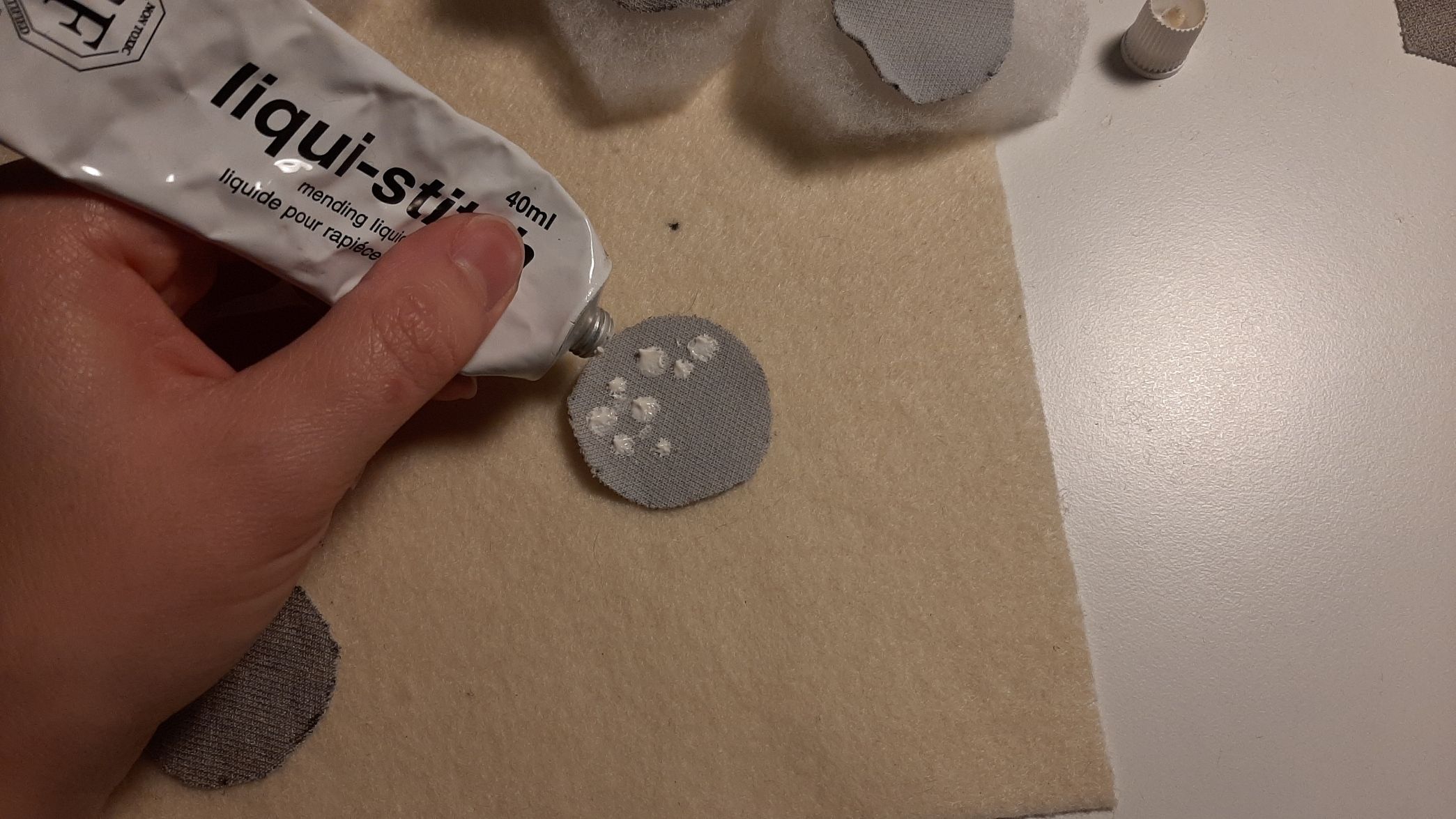
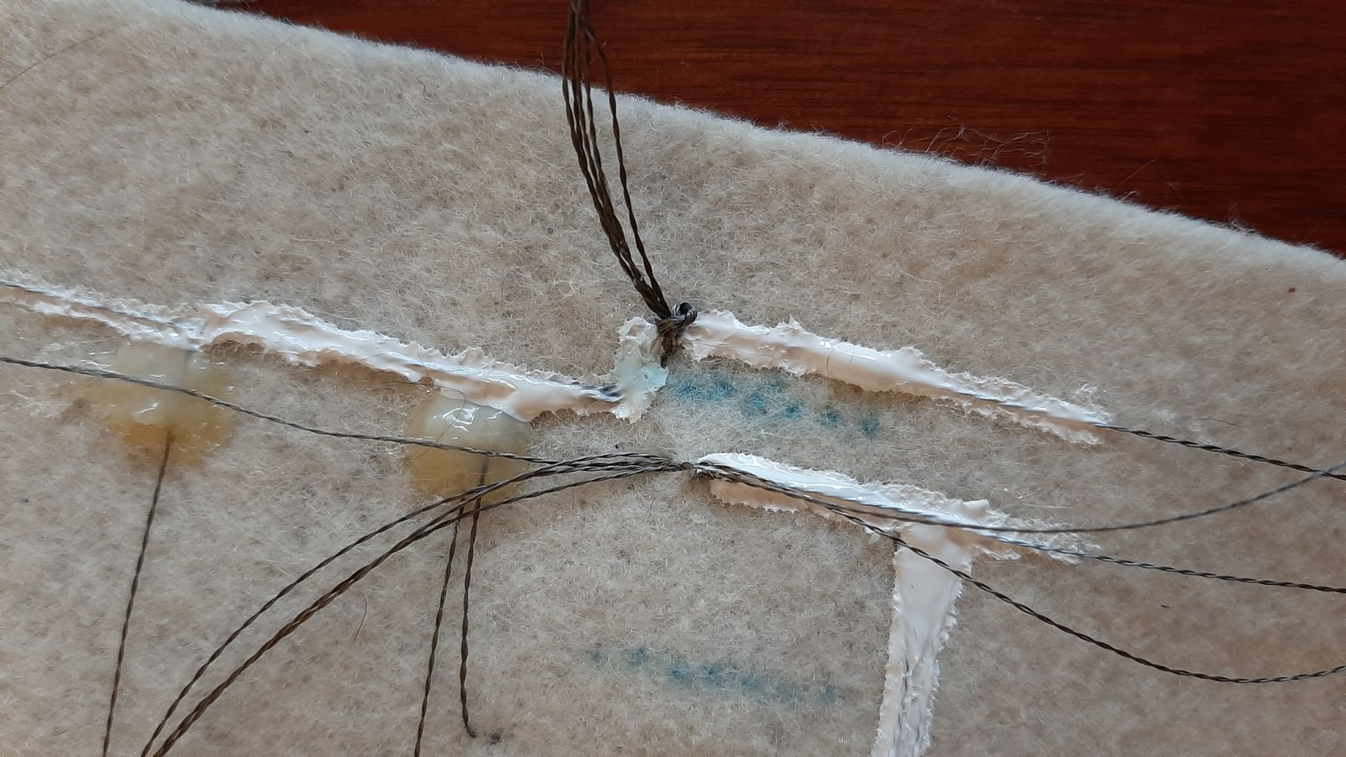
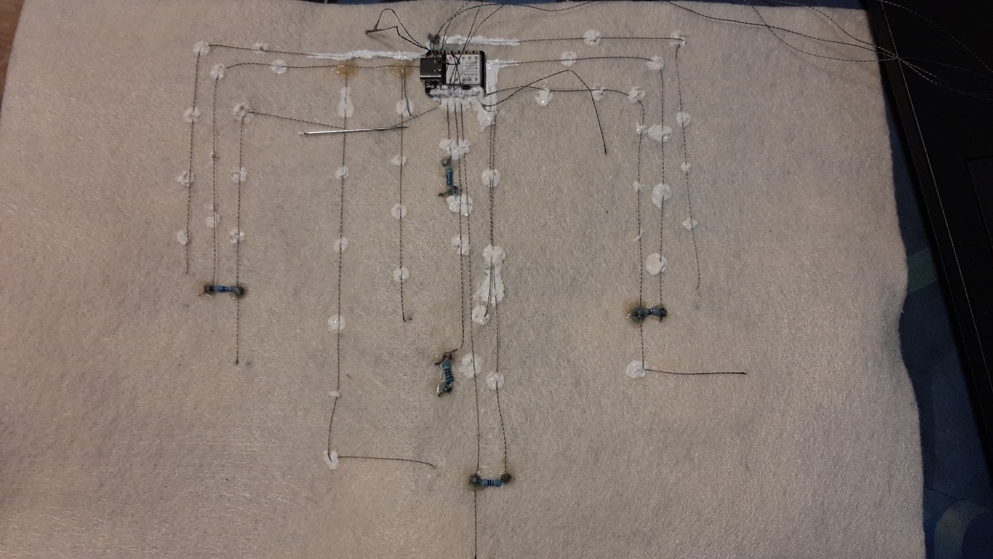
 My sewing is kind of "floating", since I wanted to be able to undo everything in case of a major mistake. It's safe for now. I would have to cover all my threads with fabric painting if I'd want a final product, because my fabric can't be folded without creating a short circut. This technique is solid, and completely invisible on the right side.
I was so nervous! I was always testing with the multimeter to see if the connections were good.
My sewing is kind of "floating", since I wanted to be able to undo everything in case of a major mistake. It's safe for now. I would have to cover all my threads with fabric painting if I'd want a final product, because my fabric can't be folded without creating a short circut. This technique is solid, and completely invisible on the right side.
I was so nervous! I was always testing with the multimeter to see if the connections were good.
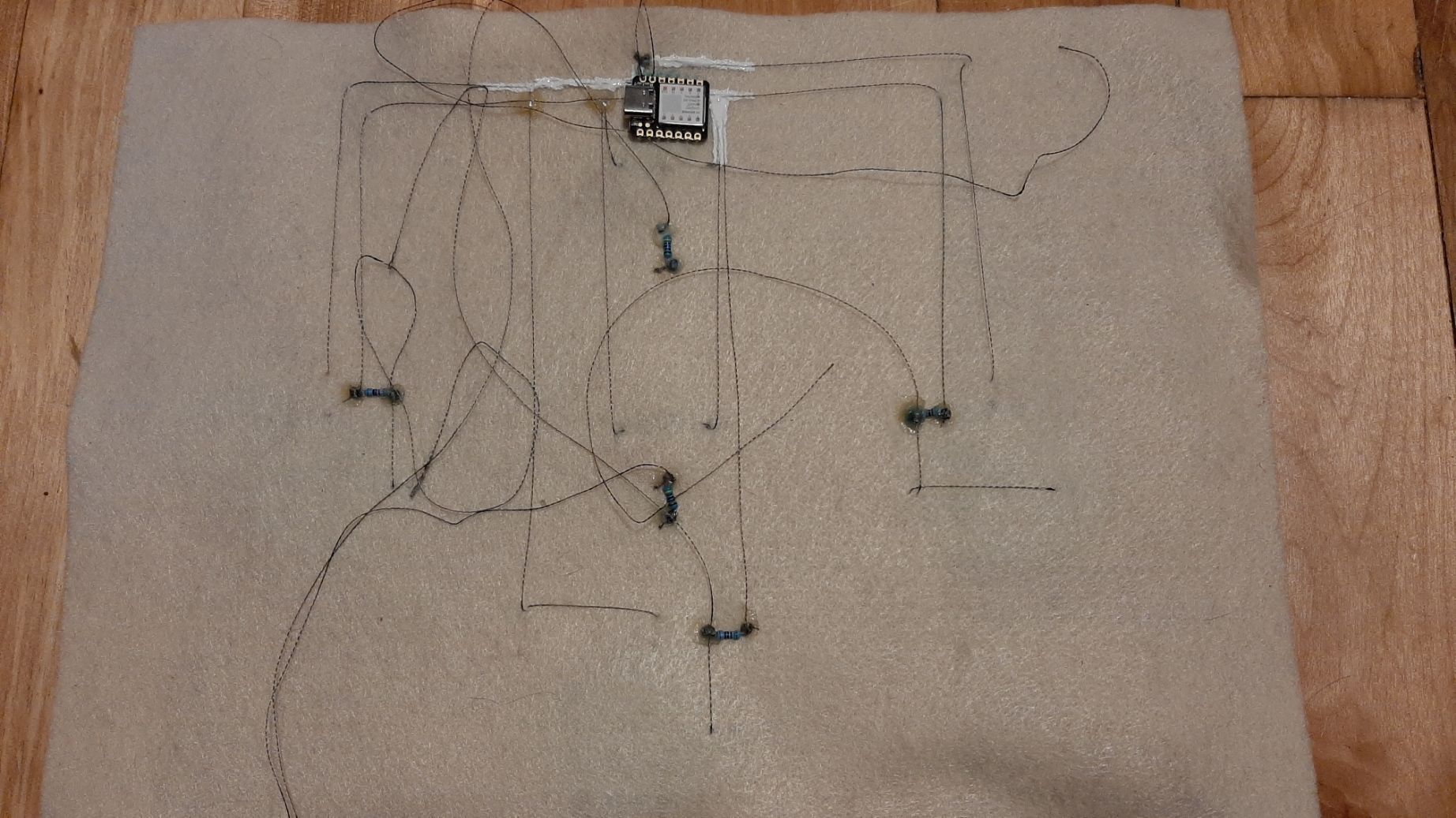
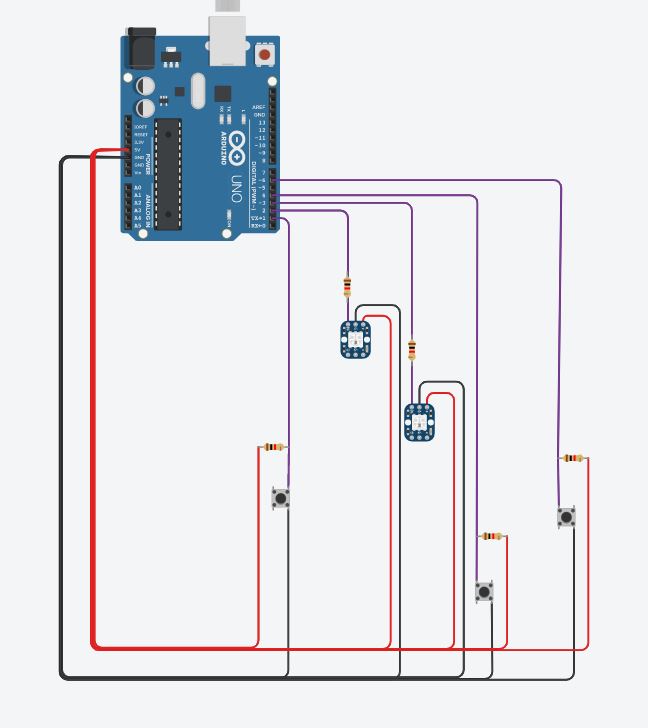
Overall, my circuit looks like this. I know it might be confusing, and it might not be the best example to follow, as it is one of my first try. I was inspired by this tutorial on how to make a circuit with multiple buttons (it gets complicated when you start coding). I also learned later that these particular leds might need a component to regulate the flow of current, to have more exact colors.
It took me a long time to understand what was happenning on my board since first: I gave my buttons a number according to the pins, but when I fliped my fabric, my button 1 was not the first, since everything was inverted. I was afraid my buttons didn't work well, but they worked perfectly. Also, somewere I inverted the programation; when my buttons are pressed, they are identified as "released".
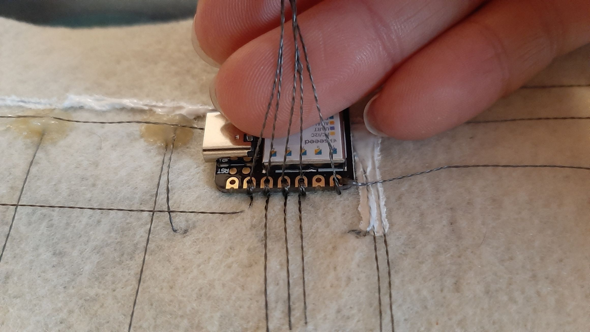
 Once my buttons worked individually, I had to fully understand my Neopixel LEDs, since it wasn't as simple as "if button 1 is pressed, Led pin = High". Those neopixels did not have a high or low state, and 5 different lines just to turn them on... I red again and again the instruction for coding a Neopixel LED I had with the example code.
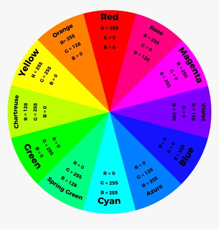
I played with different colors, and used the RGB colorwheel to get the color I wanted. It was so much fun, but a bit complicated to code with the buttons. I didn't have enough time, but now that everything is connected, I'll just play with the code eventually in my free time.
#includeezButton button1(1); // create ezButton object that attach to pin 6; ezButton button2(4); // create ezButton object that attach to pin 7; ezButton button3(6); // create ezButton object that attach to pin 8; #include #ifdef __AVR__ #include // Required for 16 MHz Adafruit Trinket #endif #define PIN 2 #define NUMPIXELS 1 #define PIN2 3 #define NUMPIXELS 1 Adafruit_NeoPixel pixels(NUMPIXELS, PIN, NEO_GRB + NEO_KHZ800); Adafruit_NeoPixel pixels2(NUMPIXELS, PIN2, NEO_GRB + NEO_KHZ800); #define DELAYVAL 500 // Time (in milliseconds) to pause between pixels void setup() { Serial.begin(9600); button1.setDebounceTime(50); // set debounce time to 50 milliseconds button2.setDebounceTime(50); // set debounce time to 50 milliseconds button3.setDebounceTime(50); // set debounce time to 50 milliseconds pixels.begin(); pixels2.begin(); } void loop() { //strip.setPixelColor(n, red, green, green); pixels.clear(); pixels.setBrightness(10); pixels.setPixelColor(0, pixels.Color(255, 60, 2)); pixels.show(); pixels2.clear(); pixels2.setBrightness(10); pixels2.setPixelColor(0, pixels.Color(255, 200, 79)); pixels2.show(); button1.loop(); // MUST call the loop() function first button2.loop(); // MUST call the loop() function first button3.loop(); // MUST call the loop() function first int btn1State = button1.getState(); int btn2State = button2.getState(); int btn3State = button3.getState(); Serial.print("button 1 state: "); Serial.println(btn1State); Serial.print("button 2 state: "); Serial.println(btn2State); Serial.print("button 3 state: "); Serial.println(btn3State); if(button1.isPressed()) Serial.println("The button 1 is pressed"); if(button1.isReleased()) Serial.println("The button 1 is released"); if(button2.isPressed()) Serial.println("The button 2 is pressed"); if(button2.isReleased()) Serial.println("The button 2 is released"); if(button3.isPressed()) Serial.println("The button 3 is pressed"); if(button3.isReleased()) Serial.println("The button 3 is released"); delay(1); }
Embroidery
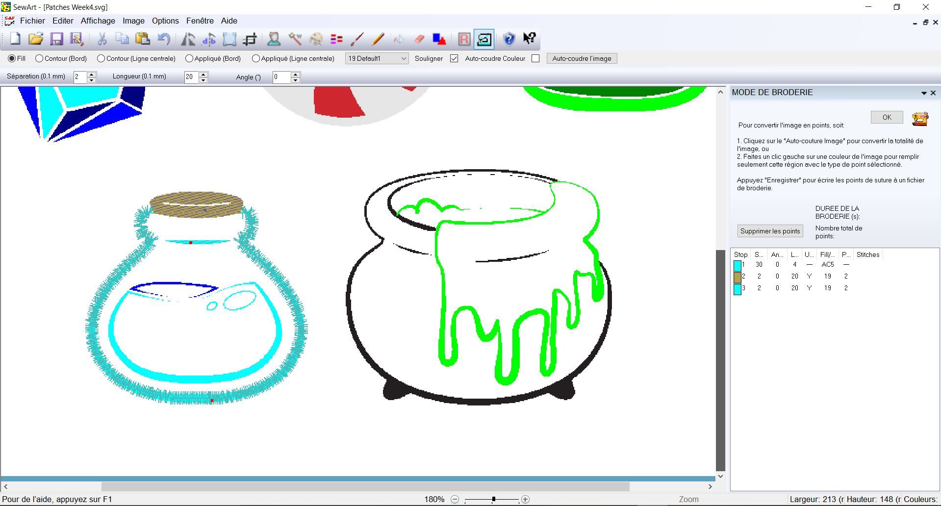
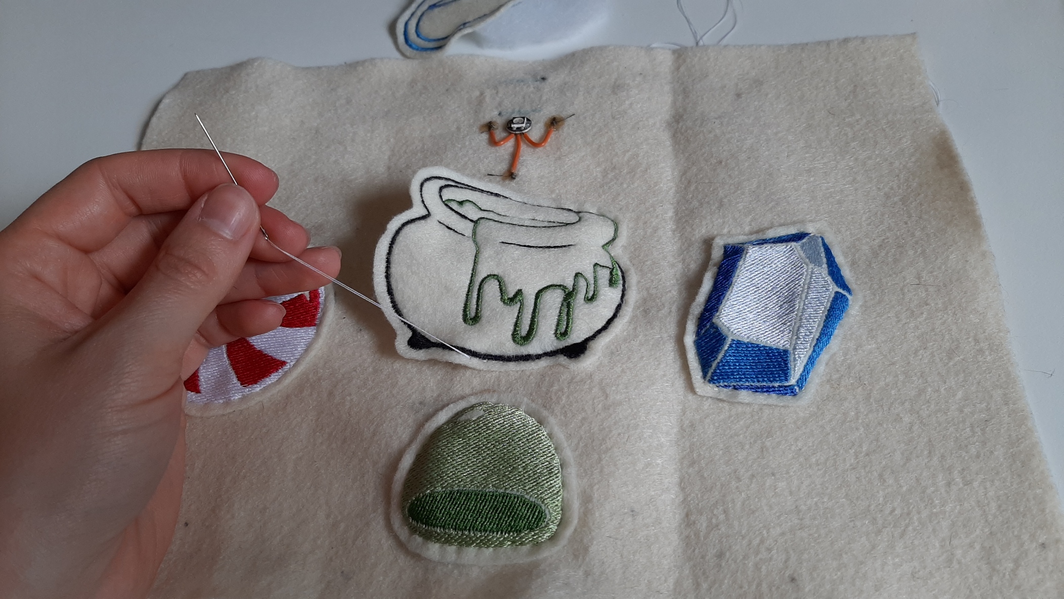
To cover the components and to finish my buttons, I covered them with cute embroidered patched. I tried all the different softwares we had available to do embroidery, because I was asking for something a bit particuliar... an outline stitch with different thickness.
SewartSewart is the software I usually use. It's pretty straightforward, you simply have to select the color you want embroided, then play with the parameters. You can select the type of sewing you want from a selection, but can't vary the thickness of an outline stitch.
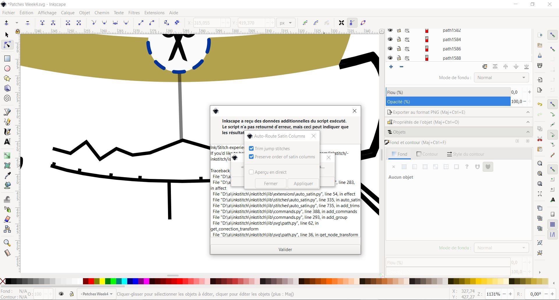
Inkstich
Inktitch is a free extention to inkscape, but is not as easy to use. The embroidery is more customizable, but even when I followed step by step instructions from youtube, I ran into some problems. It's so complicated! It would be worth taking some time to learn how to proprely use this software, but for now, let's try the next one.
PE-Design
PE-design was the software that was bought with our embroidery machine. It was a lot easier to use, and after one good tutorial, I mannaged to do exaclty the stitch I had in mind.
Download
This is an open source project. Feel free to use all the files you need!
- Capacitive Sensor Code
- Final Code
- Patches
..............
..............