Machine Design
General Idea
The idea was to create a grasshopper script that would be able to output a shape that would drive the needles using an initial black and white picture. I was responsible to write and prototype this program. I was also responsible of machining the cnc part of the machine. Everything was done in teams tough, it was very fun to see how we could all help eachother and take over when someone was getting a bit tired of their parts.
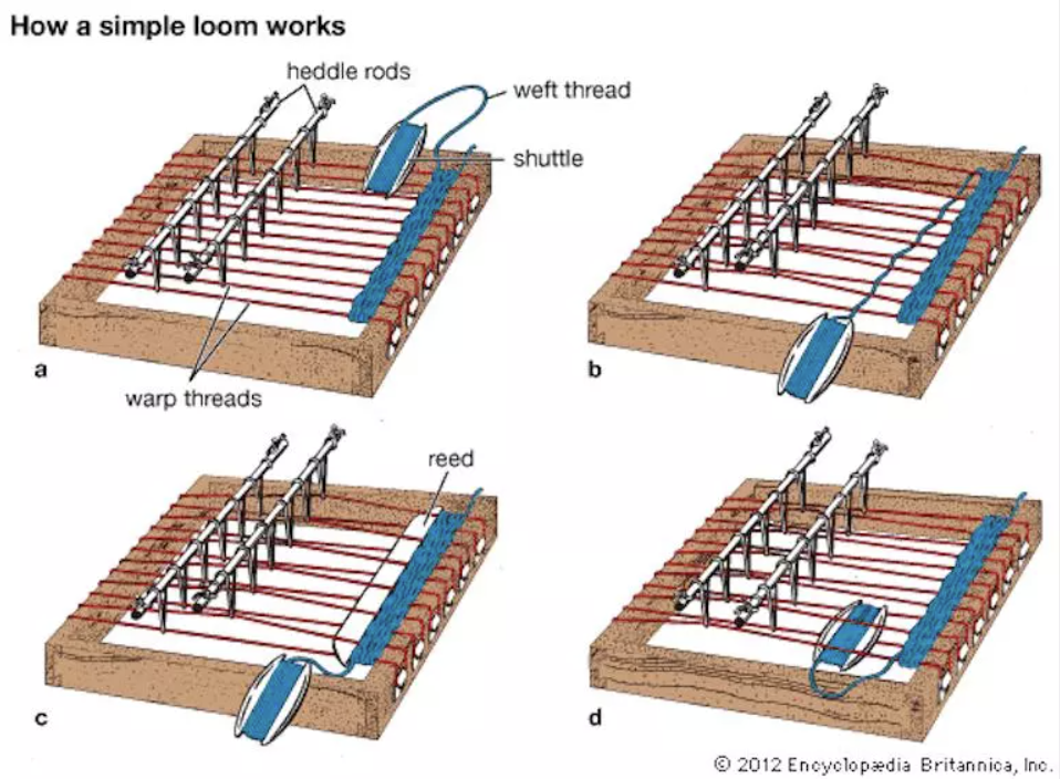
Before anything else, I had to understand what is a Loom and how does it works. I read a bit on the subject and got a basic understanding of it's functionment. Once you visualise it, the concept is pretty simple. A basic loom is constitute of a heddle wich split the different thread passing trough it. There is a shuttle that passes in between the thread. as you move the heddle to change the thread position, you can iterate the passage of the shuttle so that you create patern on your final textile.
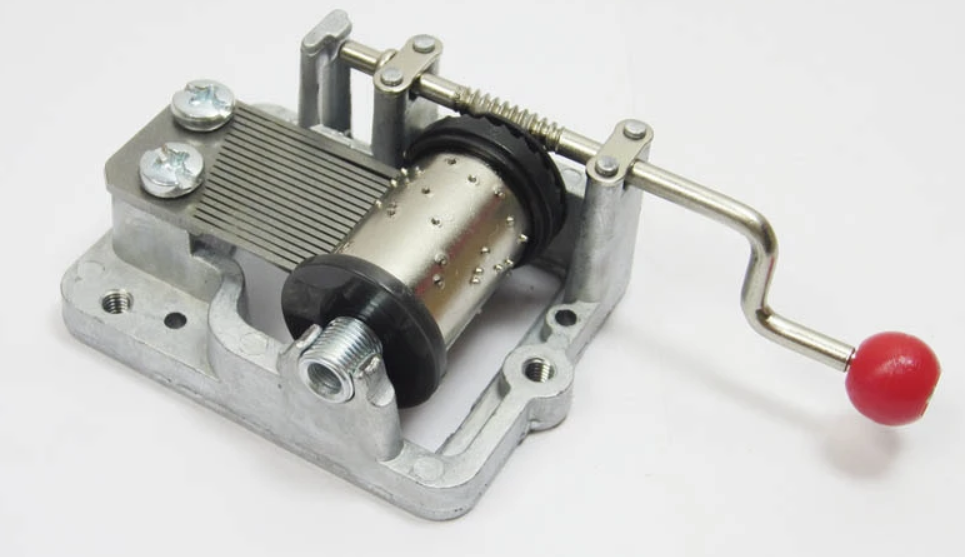
I can already see that the challenge will be to create a heddle that will have the ability to bring up or down each thread individually. Here comes in the music box and grasshopper design.
Grasshopper Design
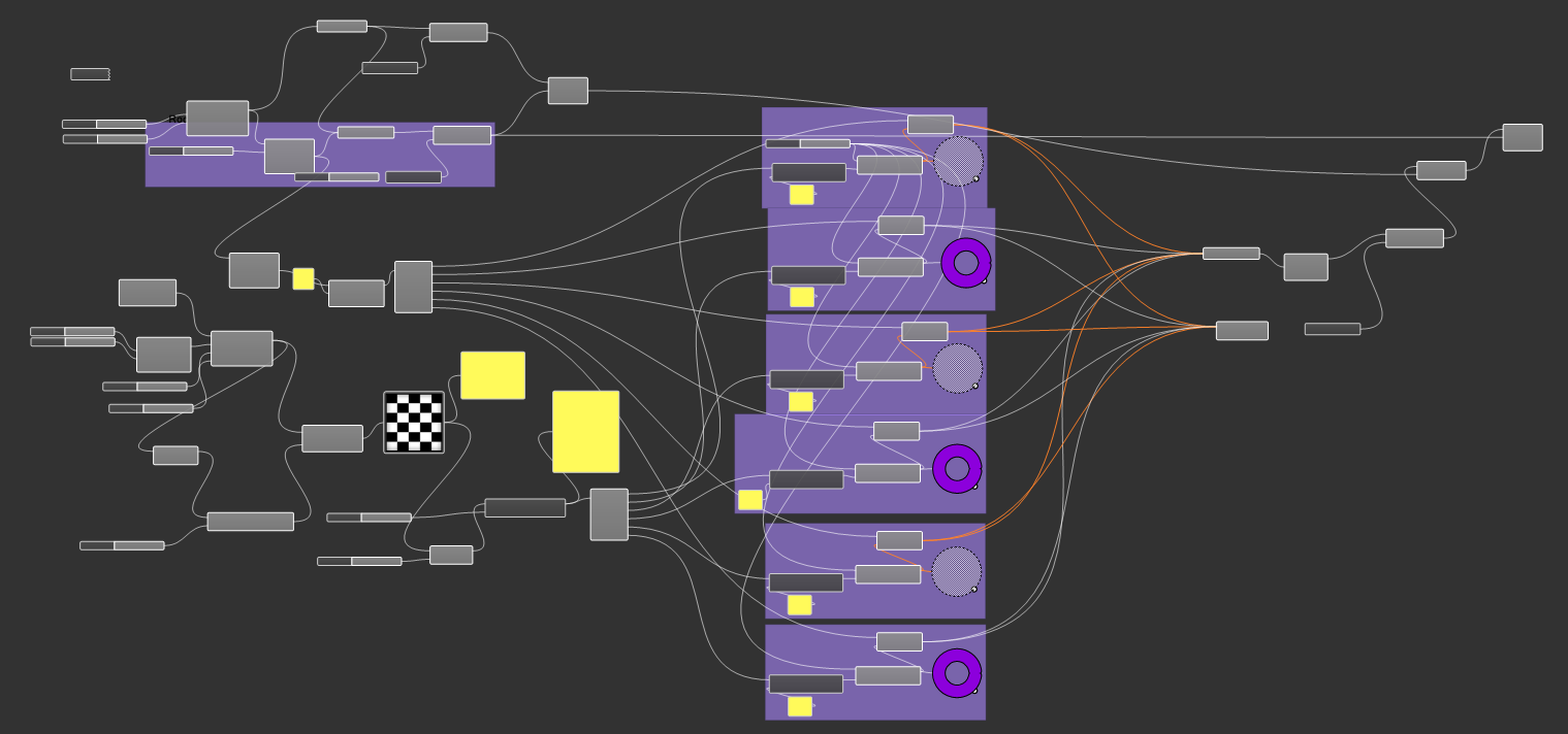
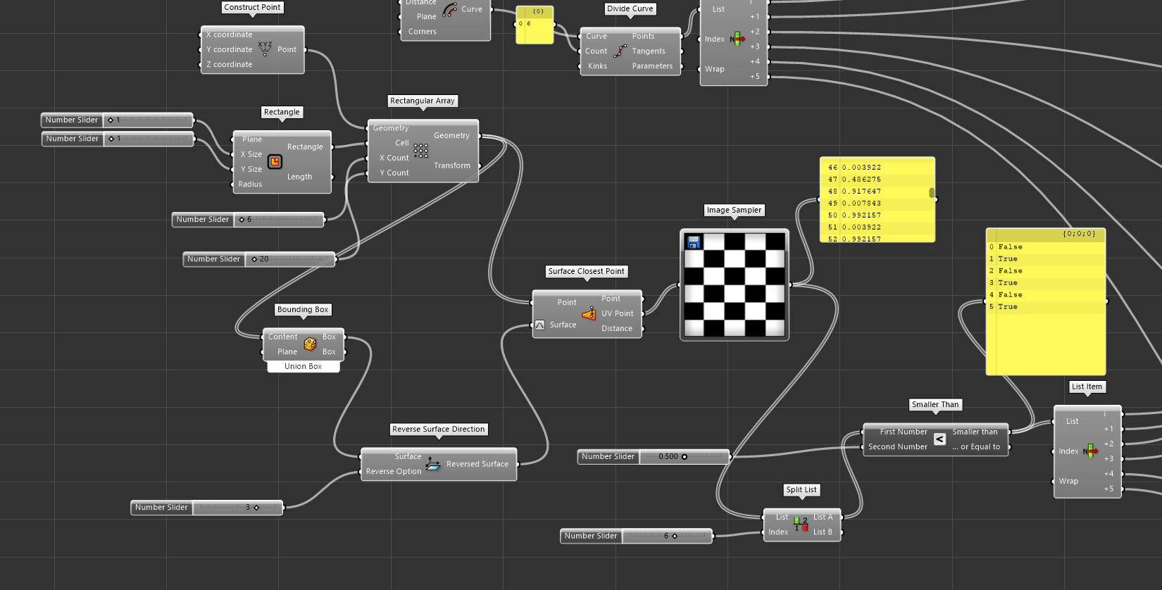
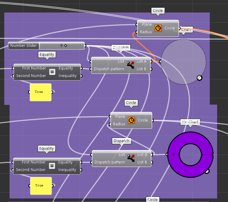
The whole design is fairly complex and far from perfect, but works as intended and could be use to generate the pattern for our loom. Here are some exemples using different picture input.


As we can see here, each time the probe read 0(white) on the picture, the shape does not merge with a circle, while it does when it reads 1(black). The Idea here is that the circle would be able to push the individual heddle so that the wire could go up and down.
This is still very experimental and would not work in this particular iteration, my goal for this week was to prototype a first based concept so that if we ever decide to come back to this loom idea we would have some ground work done. you can find the grasshopper file here
It is important to note that everything in this design is parametric and generated by grasshopper. The ground work we did for this particular script is in my opinion very interesting and has the potential to become something great. It was a challenge for us to create such a complex design in so little time, even more knowing the fact that this was not even necessary for our first loom iteration.
Machining the Loom
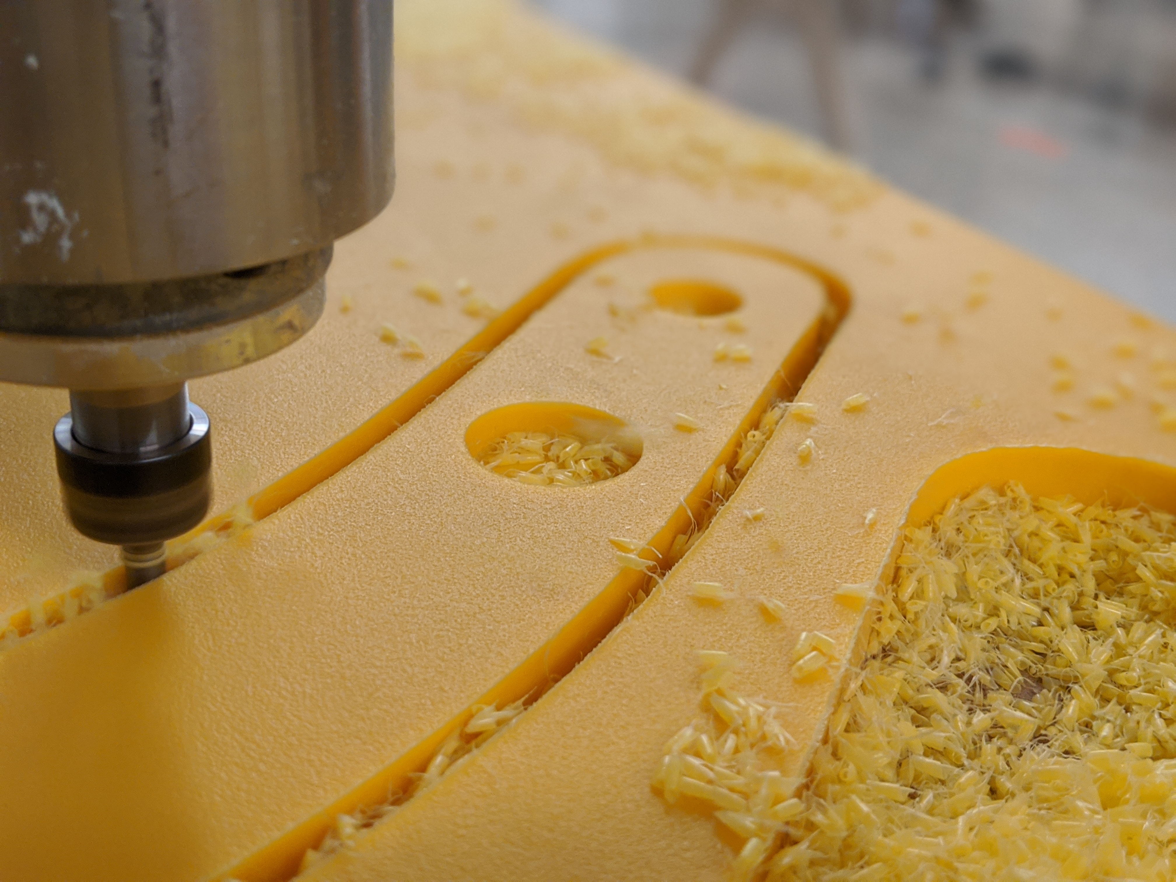
The process to prepare files for 2D machining using 3D models on rhino is very frustrating, maybe we missed some steps, but the whole thing was very counter intuitive. You have to "trim and simplify your design using all kinds of rhino function to make sure that you have no double vector or any kind of issues related to the drawing. Once the file is ready, and you gave your vector the right color using rhino, you can simply print the job to sent it into Jobcontrol. The issue mostly come from the fact that there is no 3d to 2d funtion, I was very surprised to see so little documentation on the web on this issue. Maybe it's the fact that we are used to generate 2D vector file using Fusion360 using there drawing tool from 3D parts...
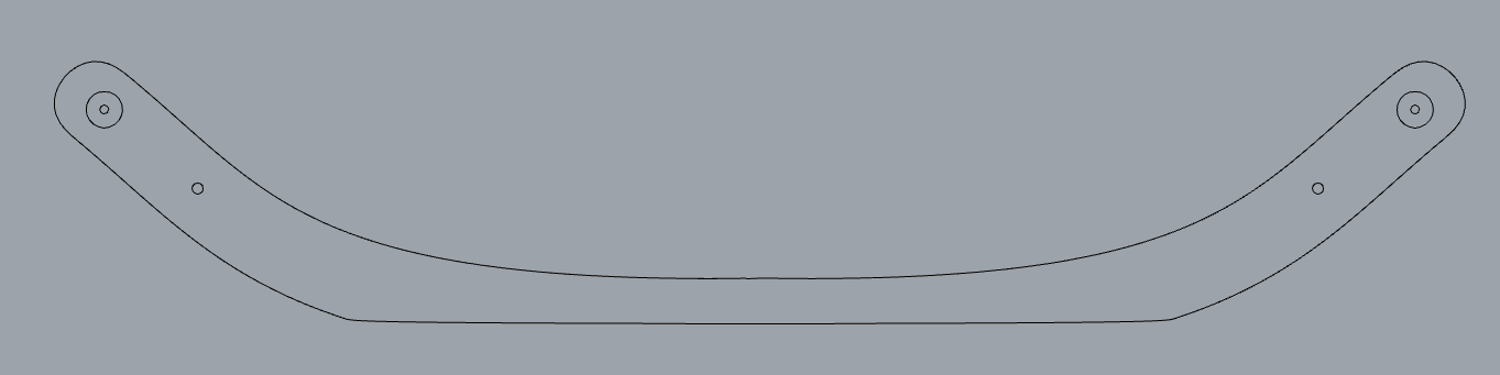
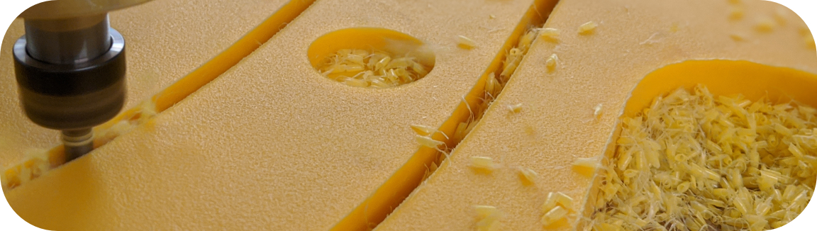
Once I successfully output a svg out of rhino, I imported it into one of my main 2D cam software, Aspire. I then created the job, HDPE is like butter for the CNC router and I'm used to cut it at very high speed. I set my feed at 3000 mm/min and my spindle speed at 24k/min. Using a 6mm mill I then made sure that we would go 5mm per pass to make sure to not put to much stress on the tool.
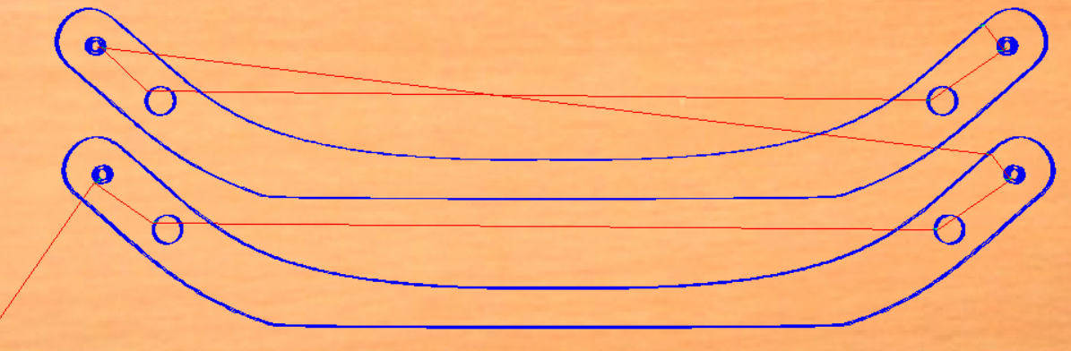
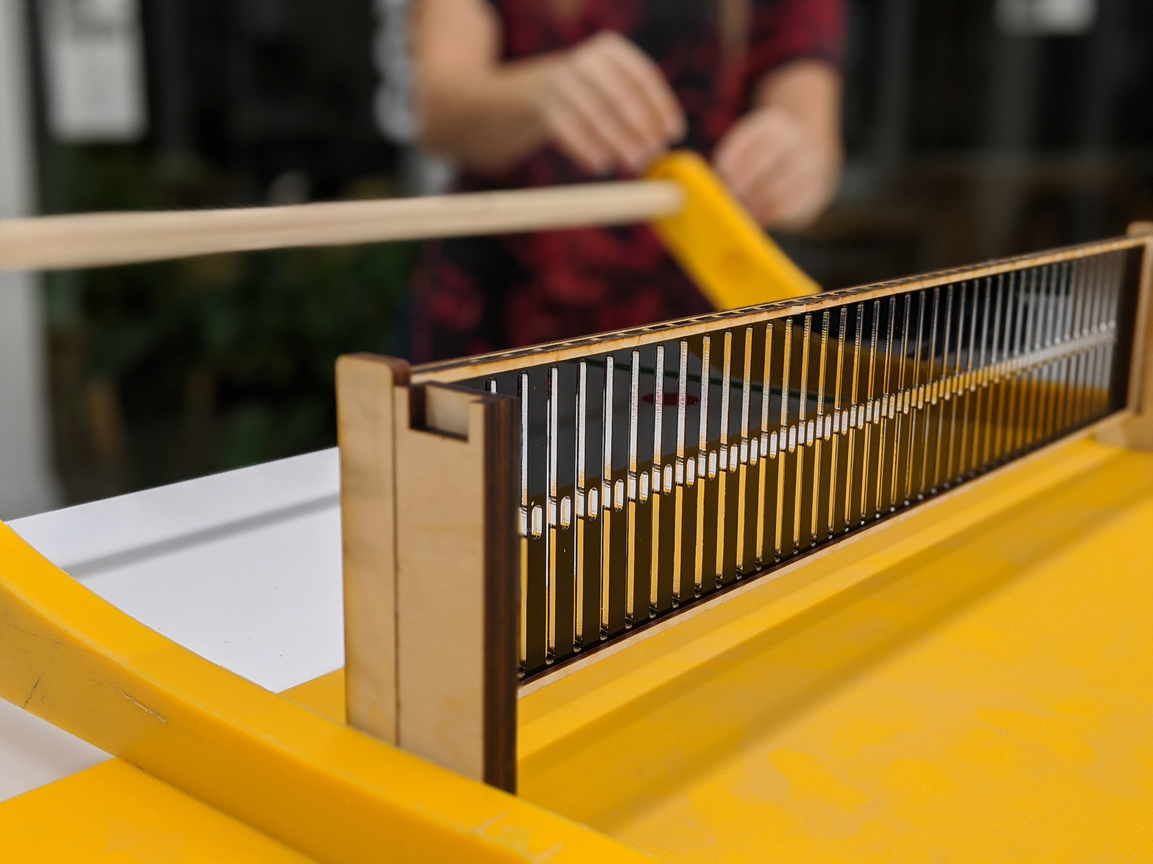
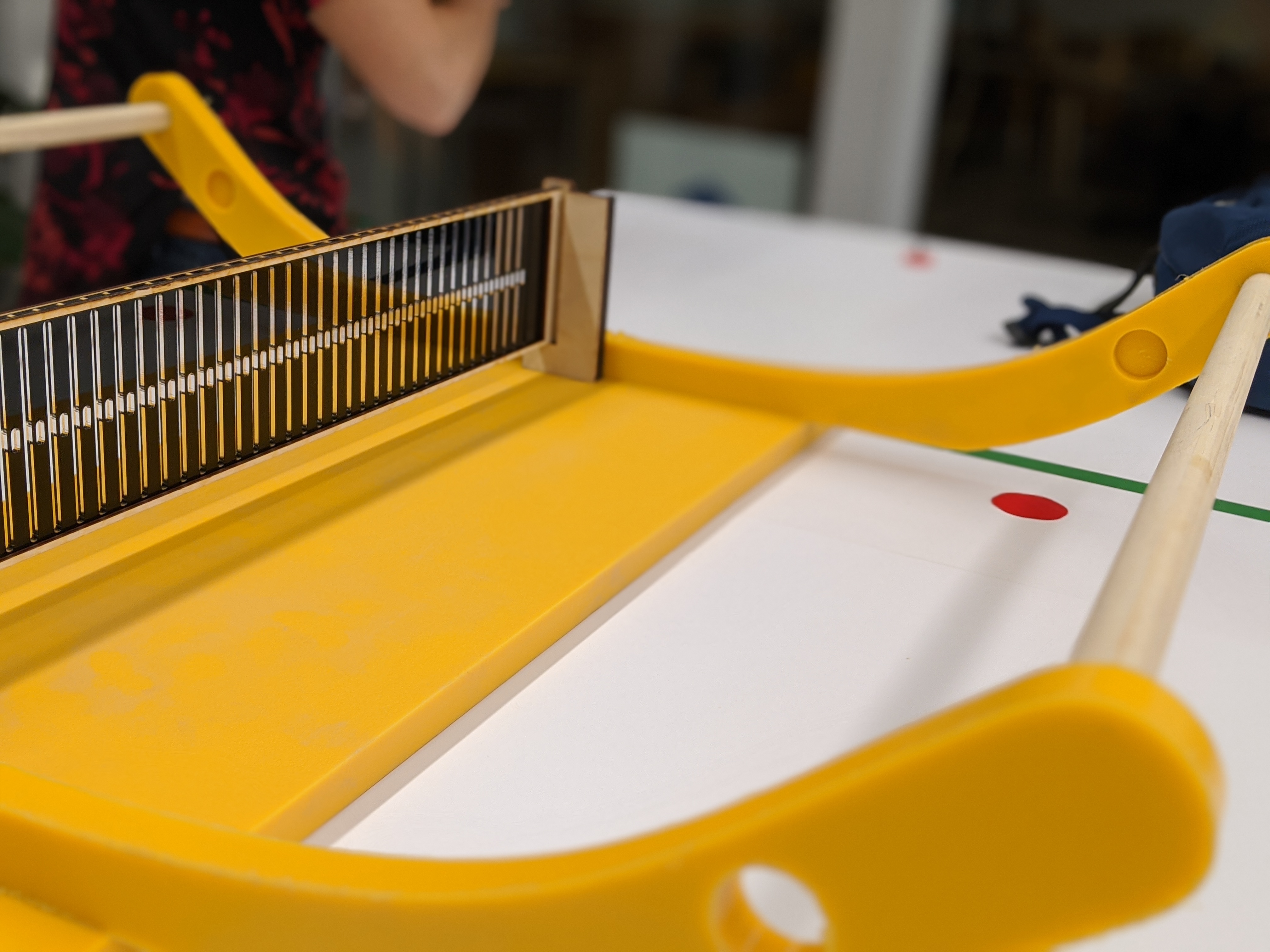
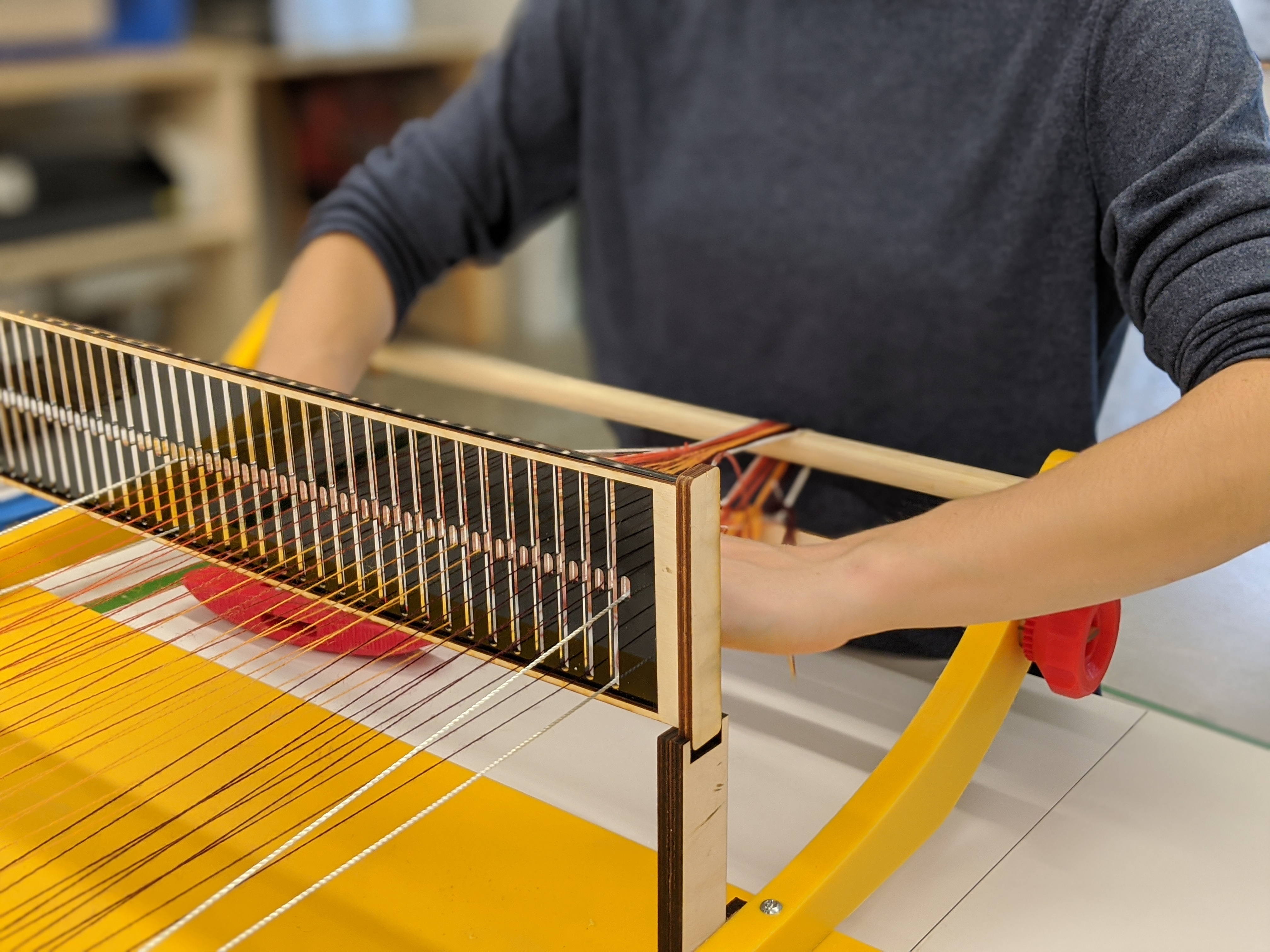
After the machining, we assembled the machine and merge everyone parts together, it was a very fun experience and I hope to find the time to keep on working on this project, but I a very happy of this first iteration.