Wearables 1
proof of concept
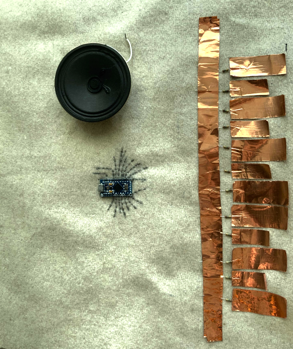
The idea of a capacitive sensor is pretty cool, the main idea for our use is to create a sensor that is able to sense the capacitance of the human body. All you really need to achieve this exept of software shananigans is a resistor and a piece of any conductive material.
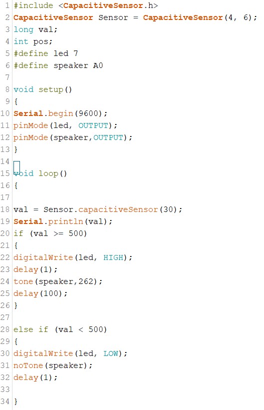
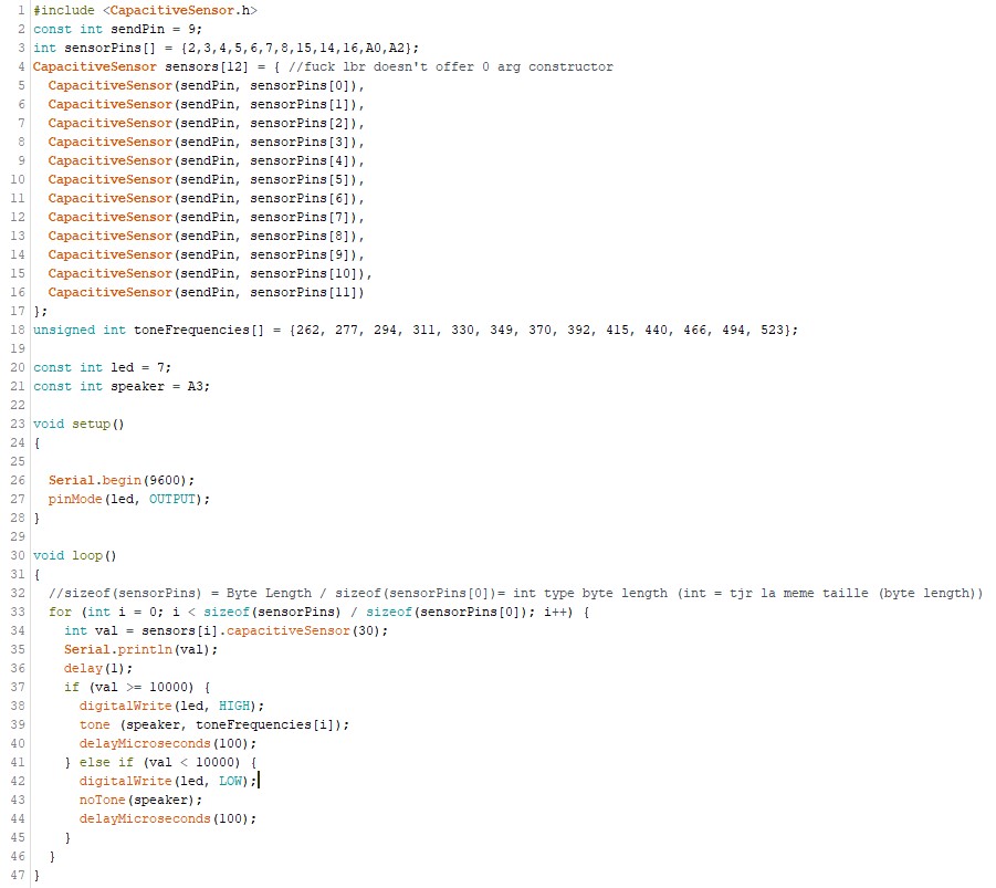
The first prototype code I wrote is very basic, I did use the capacitive sensor library written by Paul Badger. So that I could set up my capactive touch keys without too much struggle. It only consist of around 35 very simple line of code that generally just sets my variable and then create an "if" loop that check the state of my capacitive sensor and light a led and send a certain frequency to a speaker if at a certain sensibility level.
Now that the we know for sure that the capacitive sensor library is working correctly, we can think about what we actually want to do with it. My final program will consist of an array of 12 sensors and 12 different tones, this will consist of an octave. In music theory, an octave consists of 12 identifiable pitches, and those pitches repeat in the same order throughout the complete span of human hearing. The code is pretty straight forward exept maybe for the definition of my capacitive touch sensor pins, one might ask why I didn't just use a normal array definition to set my variables, after a bit of strugglin I realize that the capacitive sensor lbr by Paul Badger does not offer 0 argument constructor, so I had to define each pin of my array manually.
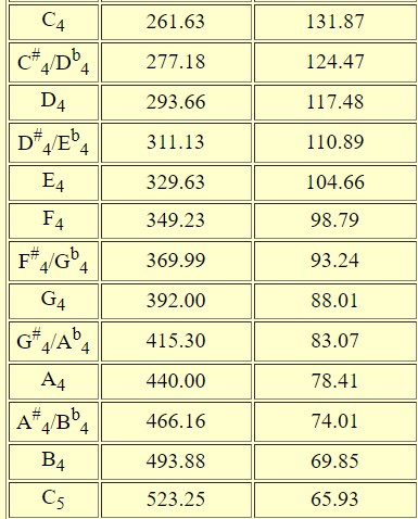
For my Tone array, the number are not selected randomly, I use this chart to convert each piano note into it's equivalent frenquency, unfortunaly, I could'nt use float since the tone function is only looking for integer.
So to keep it short, each time I pass trough to my loop, I will check the state of my 12 sensors and also attribute them a note, as soon as none of my sensors are triggered, I will make sure everything is set back to it's original state and start over.
Schematic
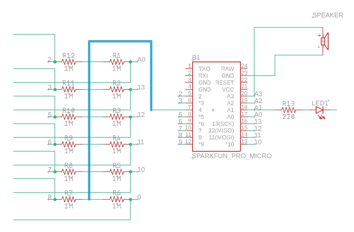
I have no need to do an actual board design for this perticular job since I won't have to mill a pcb, all I needed was to make my schematic so that my head would be clear about what goes where when doing my tie.
As you can see from my schematic, we are able to use the same send pin for each of my sensors, that's why there is a blue bus bringing all my resistors to a single arduino micro pin. I use the arduino micro since it is small and convenient while still having plenty of pin for my needs. From what I've read, there shouldn't be any reason that the code would not be able to be read on the micro.
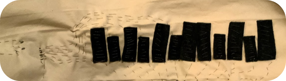
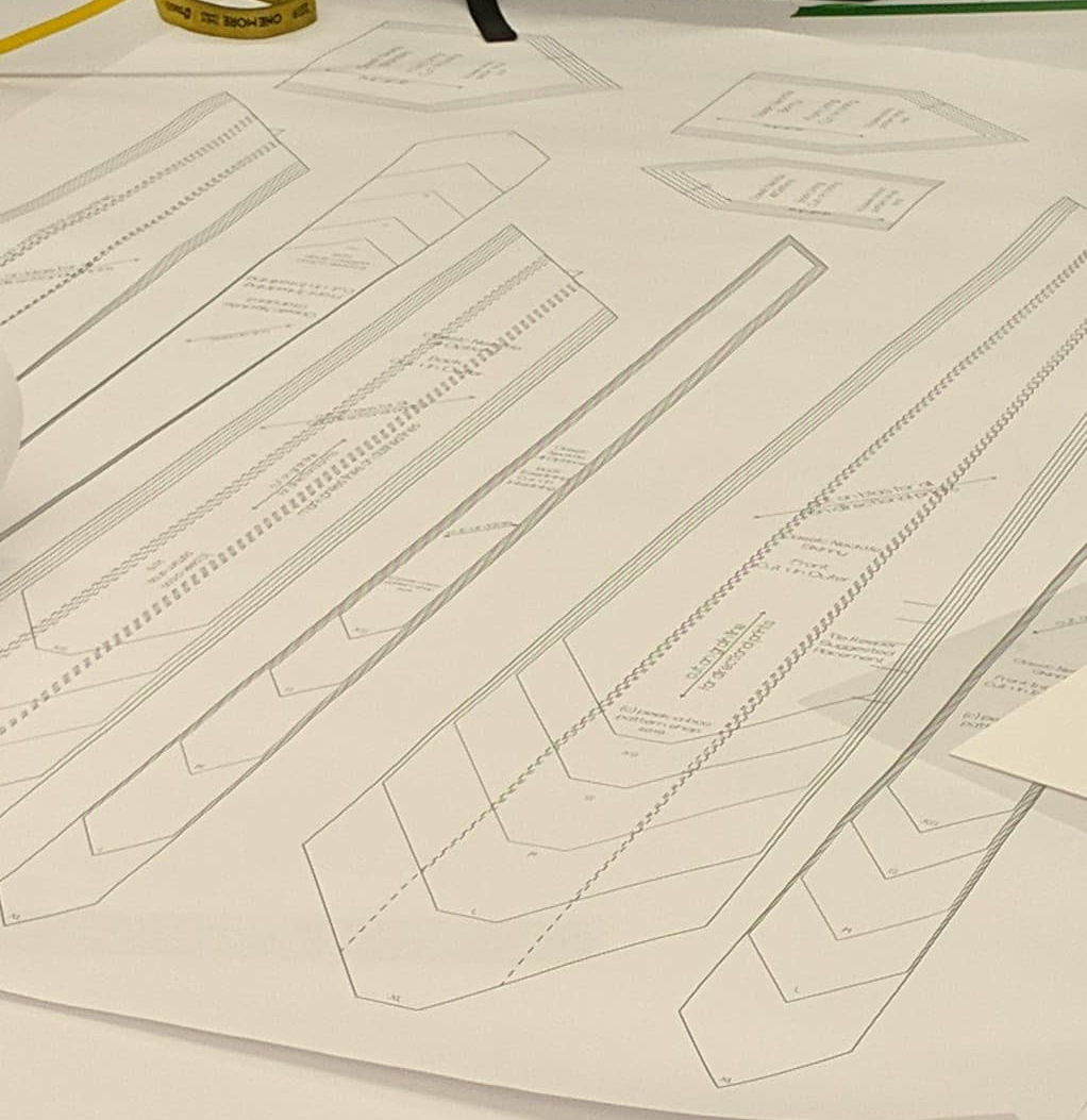
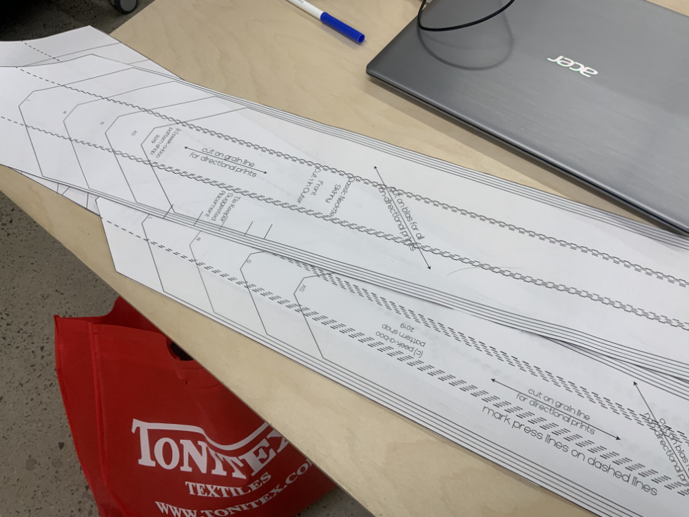
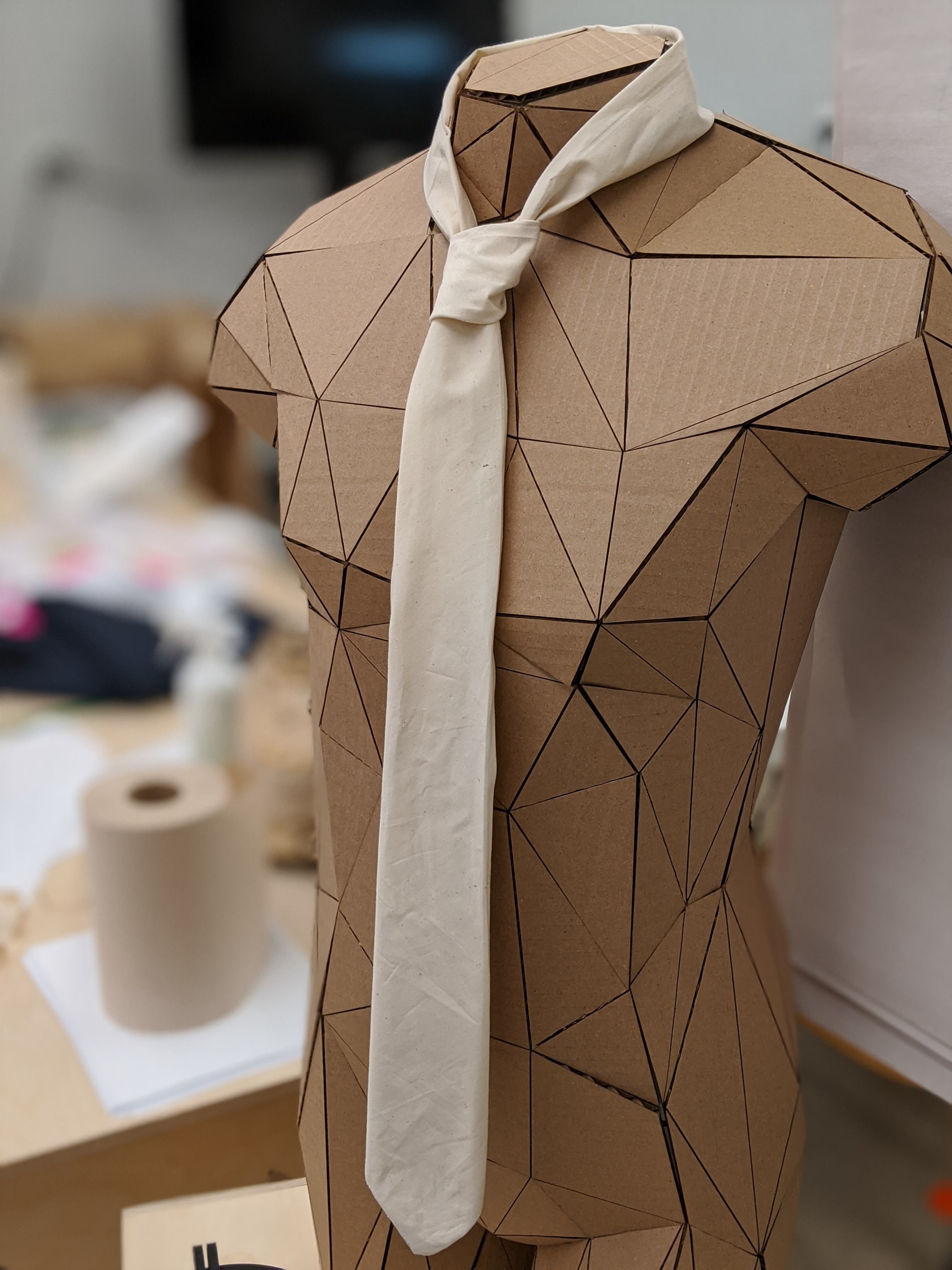
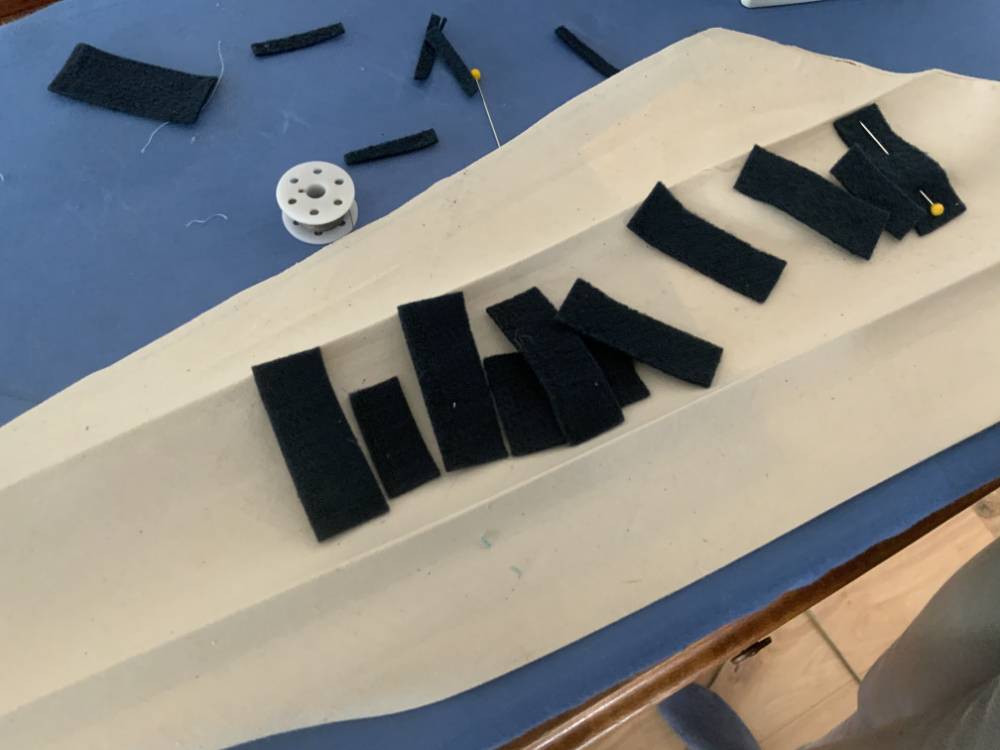
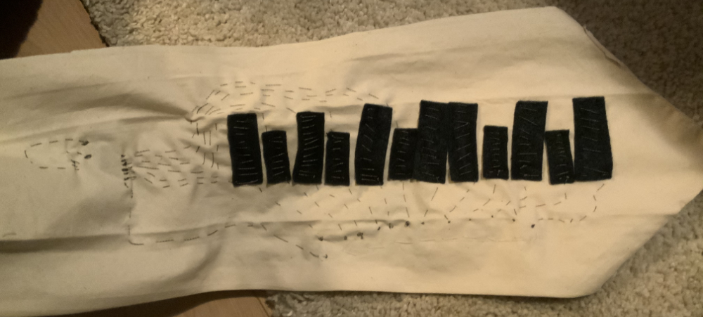
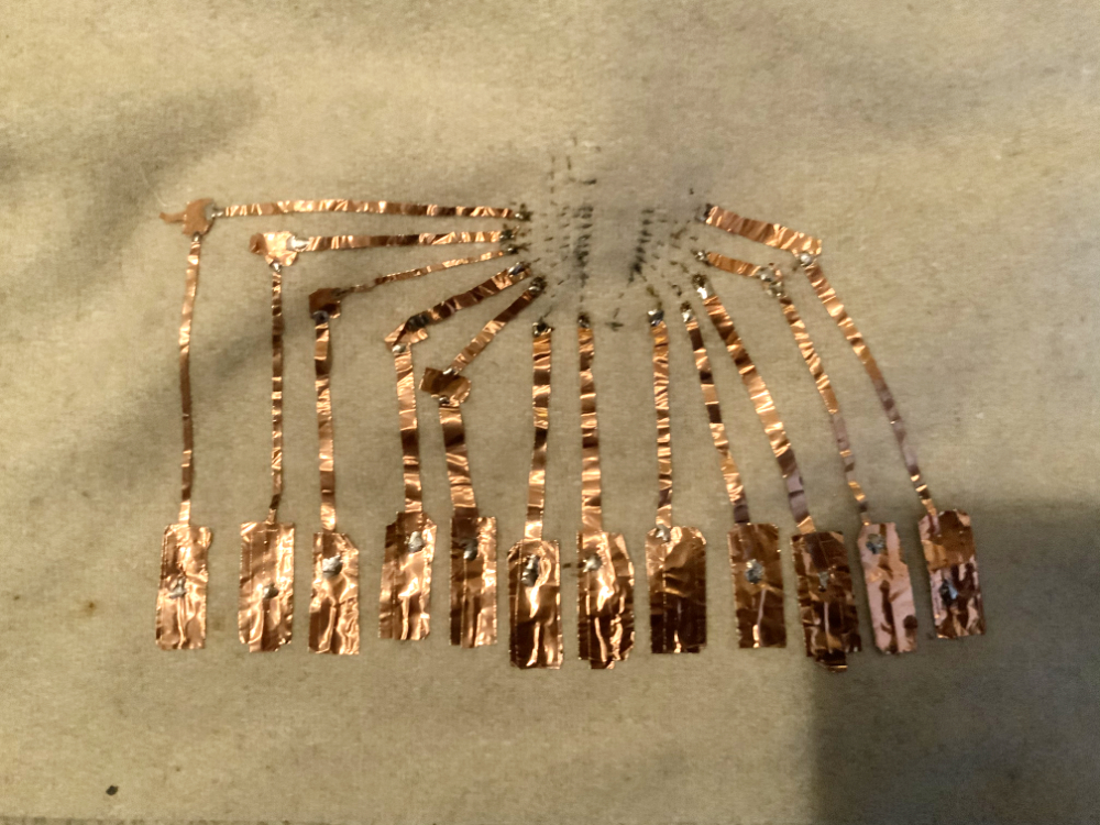
making the tie
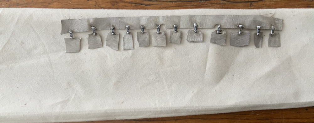
Once I had my different pieces, I start using the sewing machine. Again this was my first time, I am very lucky that Noemie was there to help me get started, I was amazed at the straight line that I was able to do! I was absolutely certain that I would be a total mess using the sewing machine.
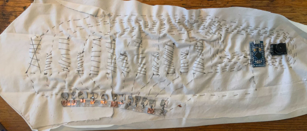
Soft circuit
The thing that I didn't took into consideration turns out to be the more crucial aspect for the functionnality of the design. First of all, the space, I had in mind that all of this would fit very well inside my tie, while I was not wrong per se, I definitively underestimate the space required for all of this circuitry to fit without creating any short. I am used to create 2 layer pcb that I can bridge and create optimal path that are able to condense the space of the actual circuit, here was not the case, I guess that I was so stressed about the sewing part that I totally forgot to worry about the placement and the isolation of eveything.
Time was the next thing I greatly underestimated, I tought that I would be able to assemble the circuitry in a couple of hours, it took me over 10 hours to sew everything together, and the more I was progressing, the more I started to realize that this may now work in the end. I felt very overwhelmed by everything that was goin on inside my tie and was thinking about solution to probleme that didn't even appeared yet. But I knew for sure that short circuit and connectivity problem were gonna occure. Oh well..
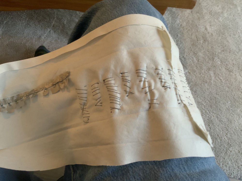
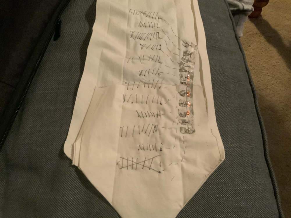
As I was anticipating, it only works in a very particular position when I pull the fabric and play the keys at the same time, and even then it sounds horrible.
back to basics
It kinda work... it's far far far from what I intended, while testing on a bread board, the keys was so responsive I could play as fast as on a real piano, here, it's just not the same, values often does not recognize my finger, I want to have a chat with my instructor so that we can brainstorm on how I could handle thing differently.
you can download the arduino code here