Skin electronics
Exploring skin electronics
For my week project, I will try to create a process where you can easily and cheaply reproduce this kind of "tatoos".
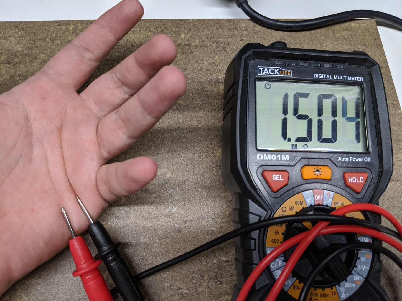
Safety measure and designing the circuit.
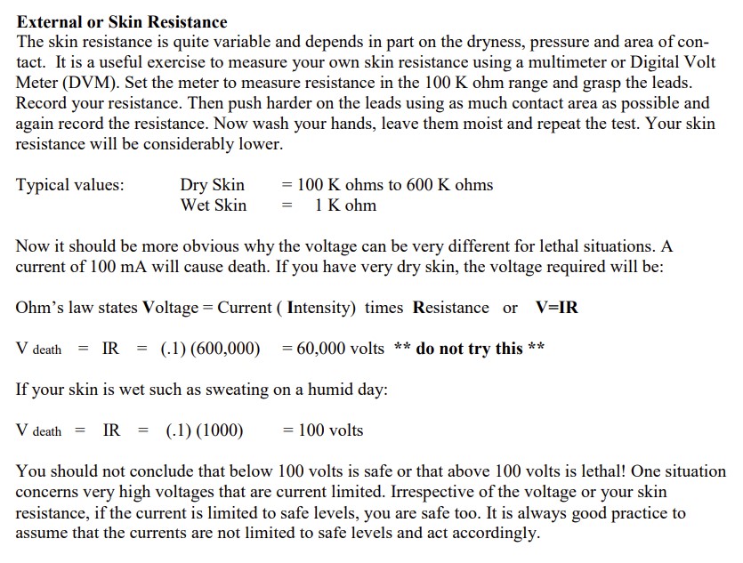
I did the test and using a multimeter tried to measure the resistance of my skin while being dry and then while being wet, the difference was pretty drastic, the resistance drop by a huge factor while having a wet skin, but even then, the resistance is more than enouph to cancel the kind of current that I want to use for my circuit.
While dry, my skin resistance was approximatively 1.5M omhs, while wet, it was down at 200k omhs.
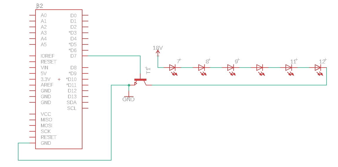
I did two iteration of my circuit, one in series and the other one in parallel. Let's assume that each of my LED needs a forward voltage of 3V to work correctly and they will each draw 30 mA. In series, you will then need 18V (3*6 Led) to supply correctly your leds, while in parallel you would only need 3V, but you will then draw constantly 180mA. If I understand correctly, the later exemple would be more "dangerous" since more current could potentially be able to flow trough your body, but at such a low voltage, the pressure would not be sufficient to cause harm.
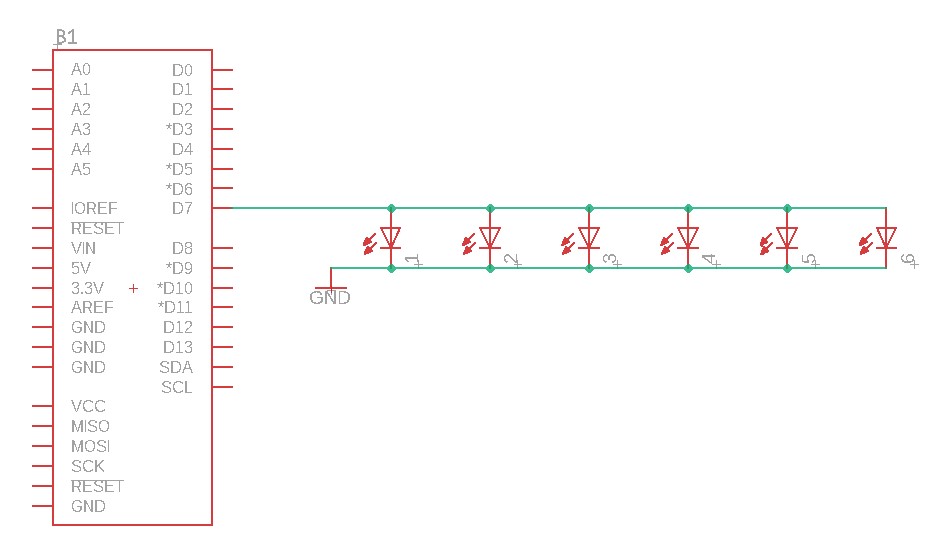
Making the printed circuit board
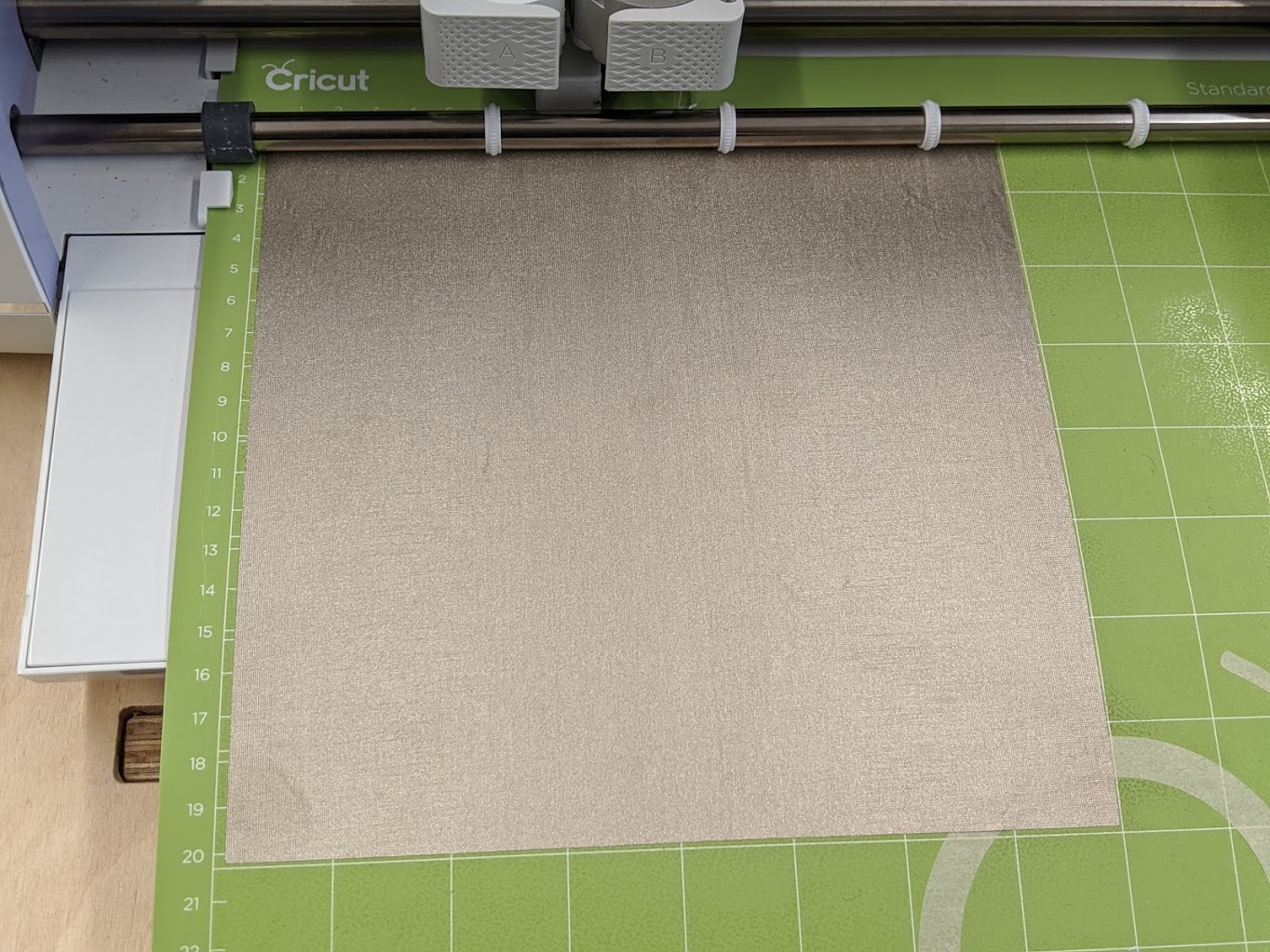
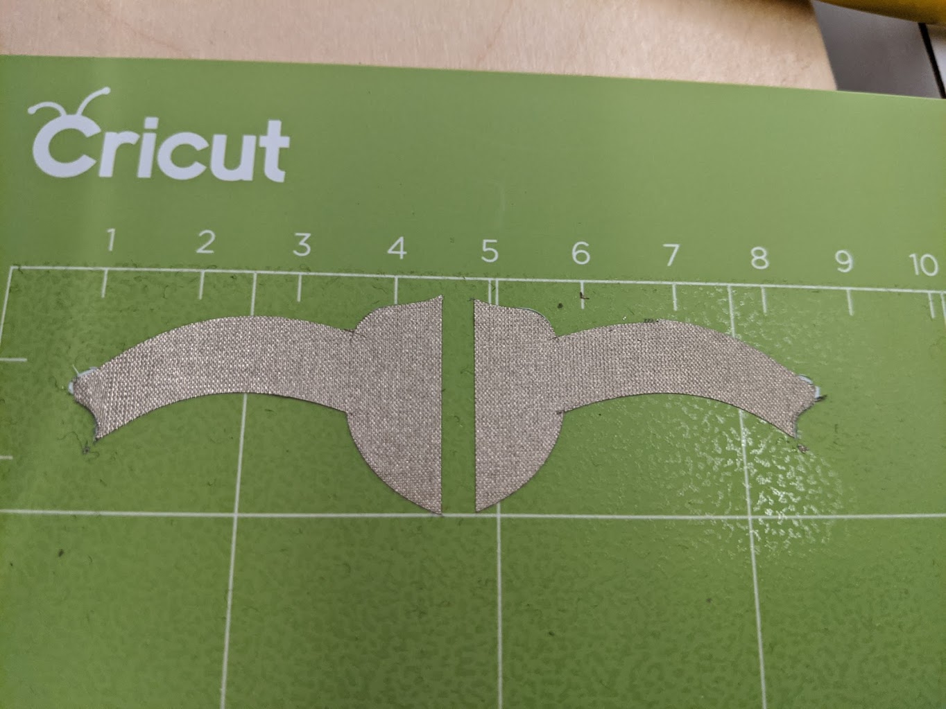
Next thing was to "draw" the circuit, to do so I used inkscape to generate some very basic shape, one shape for my in series circuit and another on for my parallel one.


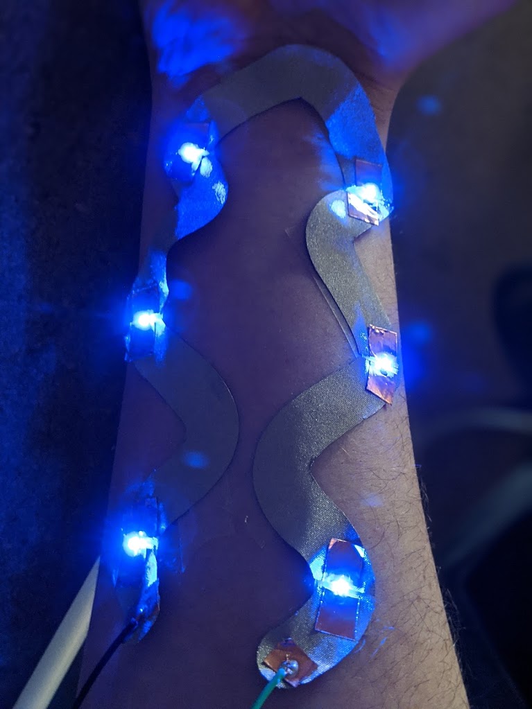
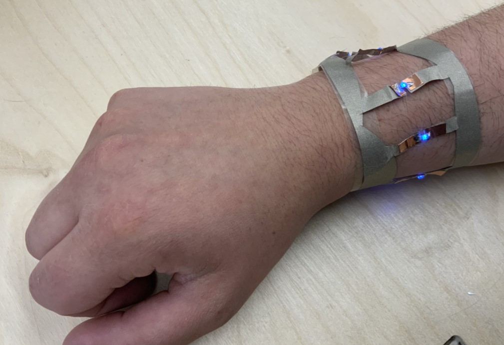
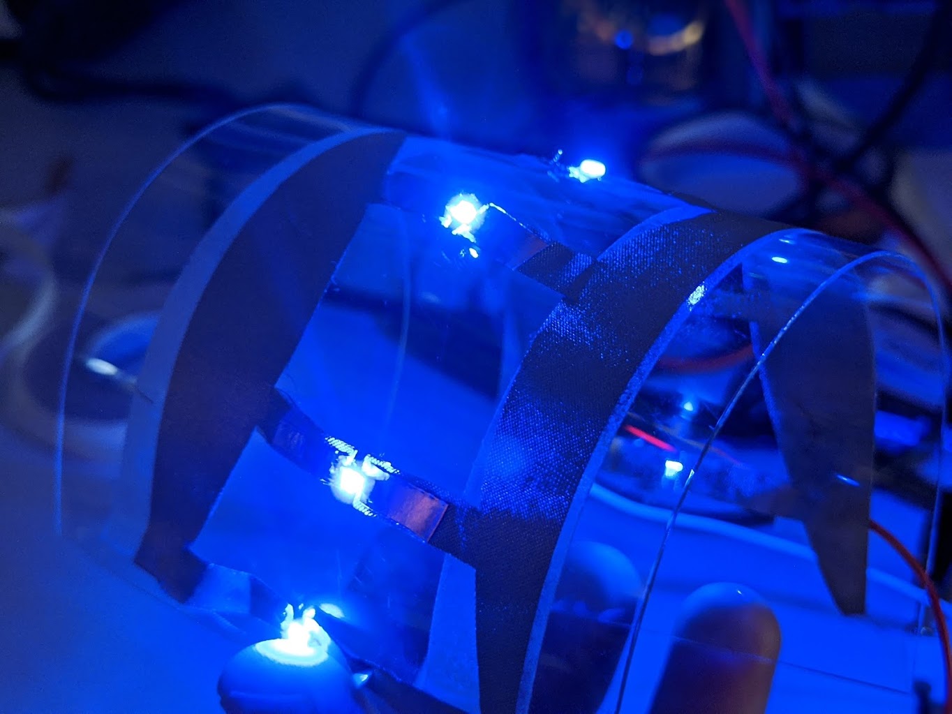
After cutting these shapes, I encoutered my first issue, I can't directly solder onto my fabric, the heat instantly melts my silver fabric. So I decided to use copper tape and create solder pads with it. The final circuit looks like this:
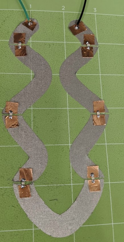
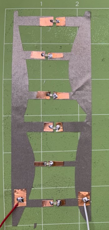
It may not be super clean, but I still find it cool, now let's try to hook it up to power to see if it works!
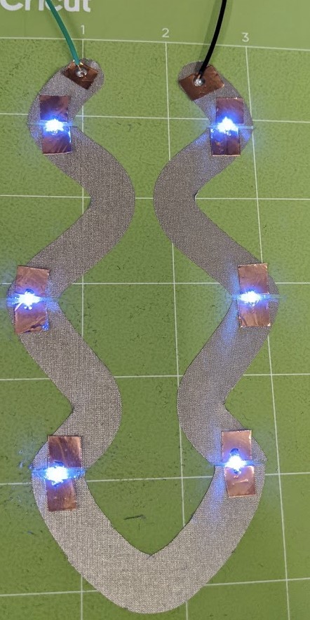
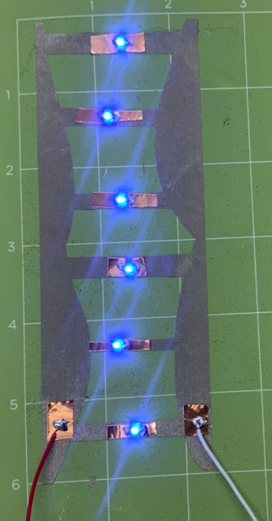
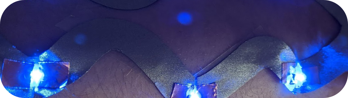
It works perfectly!, The next step is to bring it onto the skin, to do so I used transparent double sided tape and tape it to my arm, the result were pretty cool, could be better, it does not looks nor feel like a "tatoo" but it's a great start for sure!
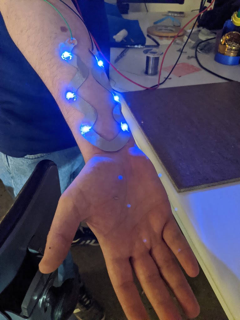
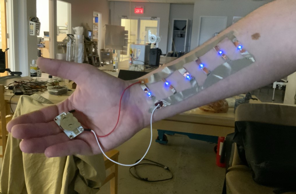
I then used a transistor and an arduino to run a simple blink program. I also had the idea to stick the circuits to a very thin PETG sheets so that I could create flexible circuit for demonstration here at the lab.
here is the very basic code for blinking my circuit:
You can find the files for this week assigment here