WEEK 13. Skin Electronics
Inspirations
During the course, Katia displayed us different projects that are really linked to a certain sensibility. She asked us the following question:
According to you, what is skin?
many answers were given.
Also, she talked about the hair, and how it is personal, but also allows one to communicate, either socially in a community, or in interhuman communication, such as embarrassment, flirting...
Here is a site that I really liked about fiber art :
Personal electronic poetic project
Grief can be a difficult and rough time to go through. I recently read the poem above, and it sounded very clear to me. I considered a lot questions about death and the importance of graves. I do think that those we love and who passed away are still around us, everything nature element can be a passage into thinking about the loved one.
Snow and poetry
This week, there was snow in Lyon, for the first time of the year. It reminded me of the following poem:
"Do not stand at my grave and weep
I am not there; I do not sleep.
I am a thousand winds that blow,
I am the diamond glints on snow,
I am the sun on ripened grain,
I am the gentle autumn rain.
When you awaken in the morning's hush
I am the swift uplifting rush
Of quiet birds in circled flight.
I am the soft stars that shine at night.
Do not stand at my grave and cry,
I am not there; I did not die."
Elizabeth Frye
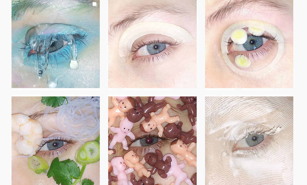
I wanted to make this makeup item an hommage to my two grandpas. Each Neopixel represents one of them.
---
"Ugly makeup"
In an Arte (french television channel) program, I discovered what they called "ugly makeup".
It displays other forms of makeup that doesn't follow the conventional way and which represent a whole new field of expression.

---
ATTiny microship
This week, we are using the Arduino UNO board to program the code before embedding it into the AT Tiny.
AT Tiny has less room to embed code, but you can you can embed.
What is an AT Tiny?
We worked with the AT Tiny 85, composed of 8 tabs in which we find the original basic components than on the Arduino UNO board.

Since nothing is written on the AT Tiny, what allows you to recognize the different tabs of the AT Tiny is the little semi-circular shaped on one side of it. (see on the schema above). When you enter the LED_pin for instance, "LED_pin 1" means the LED is connected to the 6th tab of the ATTiny.
How to connect the Arduino UNO board and the AT Tiny?
1/ Connect the Arduino UNO board with the computer
2/ Open Arduino on your computer
3/ Go in File > Examples > Arduino ISP > Arduino ISP
4/ Upload the code
5/ Disconnect the board from your computer before making the following schema with:
the Arduino UNO board
an AT Tiny
cables
an electrolytic capacitor (its short leg goes to the GND)

6/ Connect your computer with the ATTiny
First problem: the computer doesn't recognize the ATTiny.
Make sure to install the ATTiny library, using this link: https://raw.githubusercontent.com/damellis/attiny/ide-1.6.x-boards-manager/package_damellis_attiny_index.json, going into Tools > Board > Board Manager > look for ATTiny in the search bar > install it.
7/ Connect the computer to the ATTiny
Check carefully in Tools > Processor > ... that you are working with the same type of ATTiny as your ATTiny IRL.
Check carefully in Tools > Clock > internal 8mHz
Tools > Programmer > "Arduino as ISP"
8/ Tool > Burn Bootloader
9/ Open a code for ATTiny, such as the Attiny_led
Redo Tool > Burn Bootloader
Sketch > Upload using programmer
Here it is!
The code
/* Emma Pareschi, Nov 2019
 *
 *  the led connected to pin 1. it blinks
*/

int led_pin = 1;  //pin of the Led

void setup() {
  // put your setup code here, to run once:
  pinMode(led_pin, OUTPUT);   // set the pin 1 as OUTPUT

}

void loop() {
  // put your main code here, to run repeatedly:
  digitalWrite(led_pin, HIGH);      //turn the Led ON
  delay(1000);                //wait
  digitalWrite(led_pin, LOW);       //turn the Led OFF
  delay(1000);                //wait
}
On the left: the circuit with Arduino and the computer
On the right: the circuit without Arduino and the computer, aka ATTiny on its own
The computer is replaced by the 3V battery.
Project idea

Makeup is really free, and you can innovate in this field. I decided to make a grief makeup, with two diamond glints in the inner corner of each eye, and two yarns curtains (one under each eye) representing tears, but also the
The coding/circuit testing
The code I used and modified
#include <Adafruit_NeoPixel.h>
// A basic everyday NeoPixel strip test program.

// NEOPIXEL BEST PRACTICES for most reliable operation:
// - Add 1000 uF CAPACITOR between NeoPixel strip's + and - connections.
// - MINIMIZE WIRING LENGTH between microcontroller board and first pixel.
// - NeoPixel strip's DATA-IN should pass through a 300-500 OHM RESISTOR.
// - AVOID connecting NeoPixels on a LIVE CIRCUIT. If you must, ALWAYS
//   connect GROUND (-) first, then +, then data.
// - When using a 3.3V microcontroller with a 5V-powered NeoPixel strip,
//   a LOGIC-LEVEL CONVERTER on the data line is STRONGLY RECOMMENDED.
// (Skipping these may work OK on your workbench but can fail in the field)

// Which pin on the Arduino is connected to the NeoPixels?
// On a Trinket or Gemma we suggest changing this to 1:
#define LED_PIN    1

// How many NeoPixels are attached to the Arduino?
#define LED_COUNT 2

// Declare our NeoPixel strip object:
Adafruit_NeoPixel strip(LED_COUNT, LED_PIN, NEO_GRB + NEO_KHZ800);
// Argument 1 = Number of pixels in NeoPixel strip
// Argument 2 = Arduino pin number (most are valid)
// Argument 3 = Pixel type flags, add together as needed:
//   NEO_KHZ800  800 KHz bitstream (most NeoPixel products w/WS2812 LEDs)
//   NEO_KHZ400  400 KHz (classic 'v1' (not v2) FLORA pixels, WS2811 drivers)
//   NEO_GRB     Pixels are wired for GRB bitstream (most NeoPixel products)
//   NEO_RGB     Pixels are wired for RGB bitstream (v1 FLORA pixels, not v2)
//   NEO_RGBW    Pixels are wired for RGBW bitstream (NeoPixel RGBW products)

uint32_t off = strip.Color(0, 0, 0);
uint32_t white = strip.Color(255, 255, 255);

int sw_pin = 3;
int sw_status = 0;


// setup() function -- runs once at startup --------------------------------

void setup() {

  strip.begin();           // INITIALIZE NeoPixel strip object (REQUIRED)
  strip.show();            // Turn OFF all pixels ASAP
  strip.setBrightness(50); // Set BRIGHTNESS to about 1/5 (max = 255)

  pinMode(sw_pin, INPUT_PULLUP);

}


// loop() function -- runs repeatedly as long as board is on ---------------

void loop() {

   sw_status = digitalRead(sw_pin);

   if (sw_status == 0){
      // colorWipe(strip.Color(255,   255,   255), 0); // Red
      strip.fill(white, 0, 2);
      strip.show();
    } else {
      strip.fill(off, 0, 2);
      strip.show();  //display the color

    }
}

// Fill strip pixels one after another with a color. Strip is NOT cleared
// first; anything there will be covered pixel by pixel. Pass in color
// (as a single 'packed' 32-bit value, which you can get by calling
// strip.Color(red, green, blue) as shown in the loop() function above),
// and a delay time (in milliseconds) between pixels.
void colorWipe(uint32_t color, int wait) {
  for(int i=0; i<strip.numPixels(); i++) { // For each pixel in strip...
    strip.setPixelColor(i, color);         //  Set pixel's color (in RAM)
    strip.show();                          //  Update strip to match
    delay(wait);                           //  Pause for a moment
  }
}
What I modified from this code I found in Emma Pareschi's course:
LED_COUNT = 2 ; means that two LEDs are lighted up by the code
uint32_t white = strip.Color(255, 255, 255) ; to code the white color
To code other colors
**Testing the circuit without Arduino (one LED and the Attiny)
When you are working on
Looking for the circuit that would fit my idea of curtain makeup

Testing the circuit on paper
Now that I know that the Attiny is correctly programmed, I make the circuit previous theorical circuit on paper, using conductive thread and the components of the circuit.
Time to embroider
Bill Of Material
Material for the electricity part :
1 ATTiny chip
1 socket for the ATTiny
1 coil of Stainless Thin Conductive Thread
2 Flora Neopixels V2
1 3V flat battery
Material for the textile part :
1 strap of lace, of the exact length of your head measurement
1 pair of metal clothes hooks
)
Unfortunatly, the design doesn't work, but here are pictures of the final result


Possible reason: two paths of conductive thread are touching each other, creating a short circuit. It is very delicate to embroider such a thin piece of lace, making sure that the conductive thread aren't touching each other.
Also, the ATTiny socket's tabs are very close to each other, which means that to fix then onto your design, you have to wrap them in conductive thread (for the contact to be good). But if you do that, you have to make sure that the conductive thread wrap doesn't touch another piece of conductive thread : it would create a short circuit.
There is something I hadn't taken into account : my lace was stretch, so the size of the accessory was perfect to fit on my head ; nonetheless, the conductive thread was not stretch : the final piece doesn't fit around the head anymore. It is such a pity ! This is why I recommend you to use the metal clothes hooks to fasten and defasten the accessory.