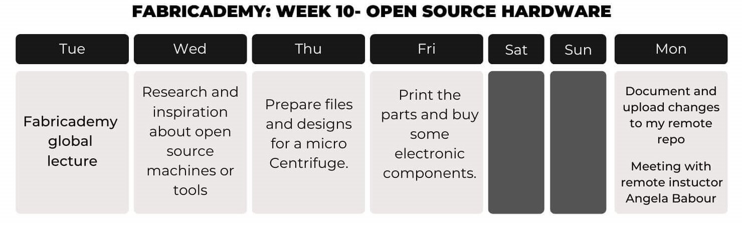
Week 10- 22/11/2022

Open Source Hardware
- from fibers to fabrics

Scroll For More

Nov 22, 2022

Open source hardware- from fibers to fabrics

The class explores the open source hardware field in general and focuses on its potential in the area of textile.


1. Weekly Documentation planning

How I worked this week

2. MicroCentrifuge

Laboratory centrifuges spin a sample at high speeds in order to separate particles in suspension. Centrifuges are found in many types of labs including biological, environmental, pharmaceutical, and clinical labs. Microcentrifgues differ from standard laboratory centrifuges in the size of the tubes used.

Standar MicroCentrifuge. Source
0.5mL Microcentrifuge Tubes with Attached Caps.Source.

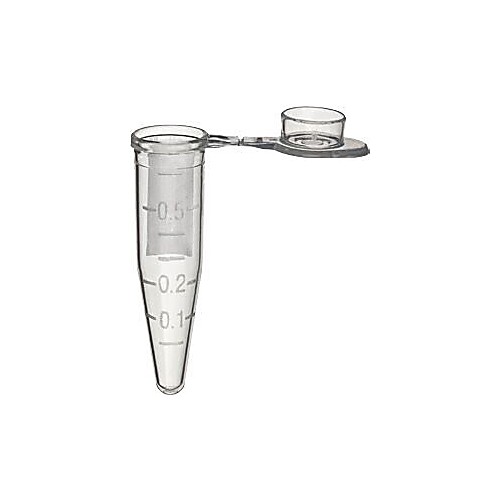
Microcentrifuge tubes are much smaller than standard tubes, generally in the 1.5-mL to 2-mL range, though models that support larger or smaller tubes can be purchased. When purchasing a microcentrifuge, it is important to consider temperature range, equipment size, speed, and size of centrifuge tubes accepted.Source.

2.1. Inspiration and research

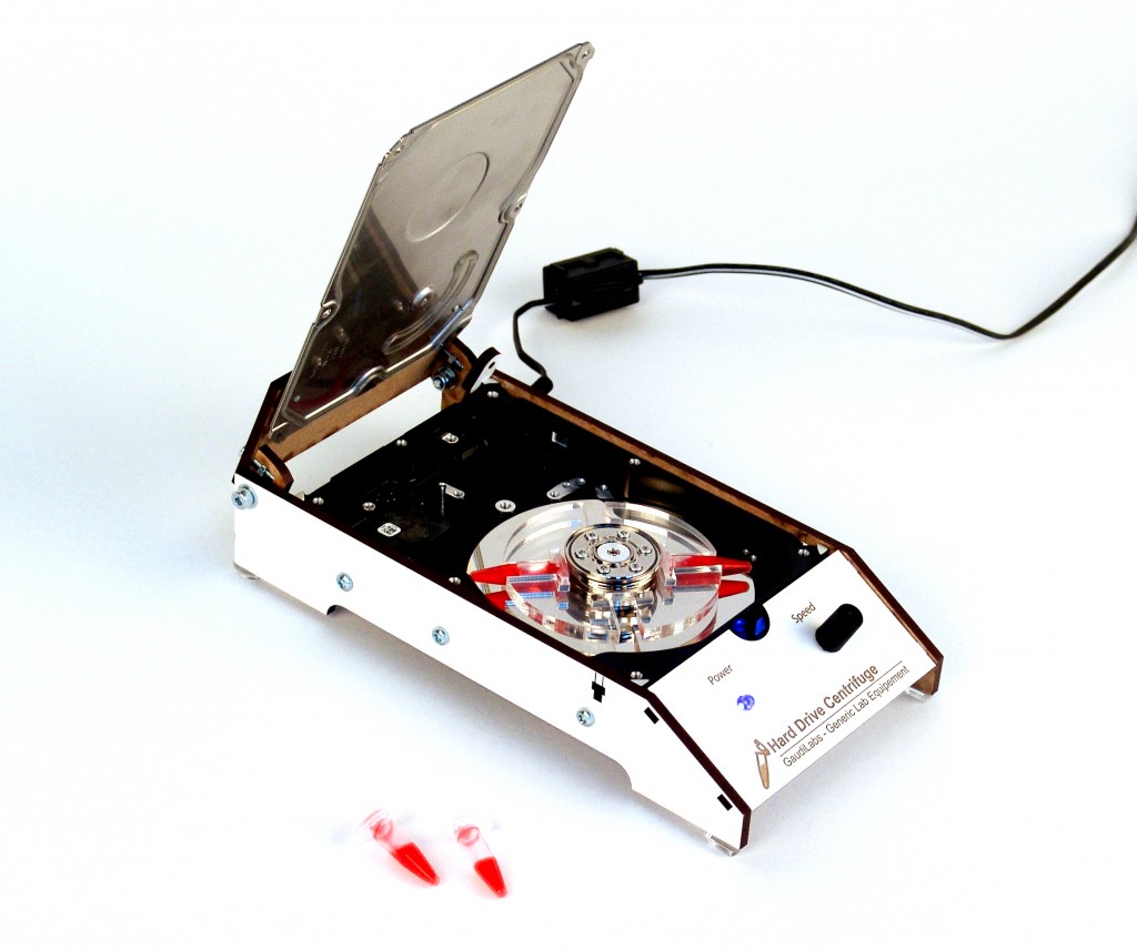
I found a lot of great examples about this centrifuges, here's a recap of some of them:

OpenFuge: An Open-source Centrifuge

In this next example I like the simplicity of the product, simplicity when it comes to design and also electronics. I think I'll use the same system.

A low-cost and open-source mini benchtop centrifuge for molecular biology labs
3D Printed DIYbio Centrifuge (V3)
Hard Drive Centrifuge

p


2.2. Computer-Aided Design (CAD):

For some parts of the project, specifically the Rotor and the motor mount, I use the design of 3D Printed DIYbio Centrifuge.(V3) However, I made minimal changes to adapt to the electronic componets I bought.

Using Rhinoceros I tried several shapes thinking about aspects like usability, transportability and stability. Also about the types of technologies that'll be using to fabricate my idea.Here are some pictures of the different designs I made:

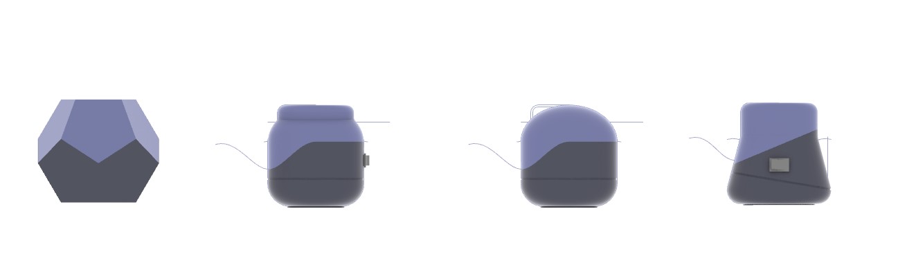
After some thoguhts, I pick this design:

2.3. Electronic components

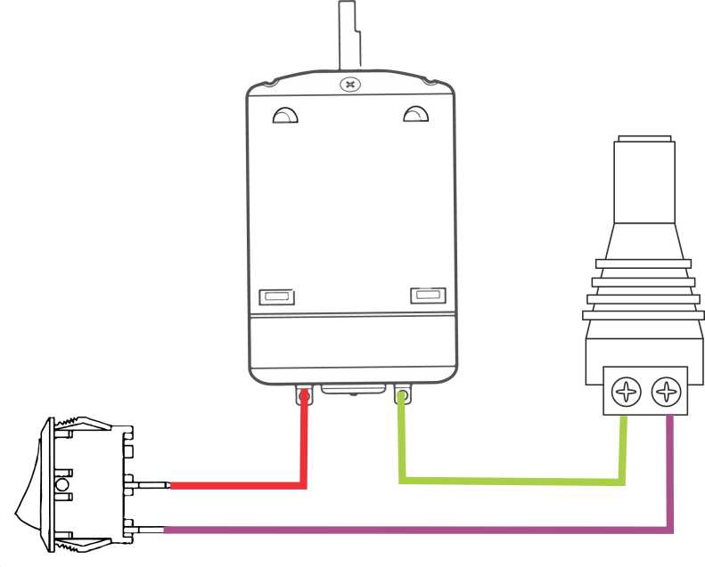
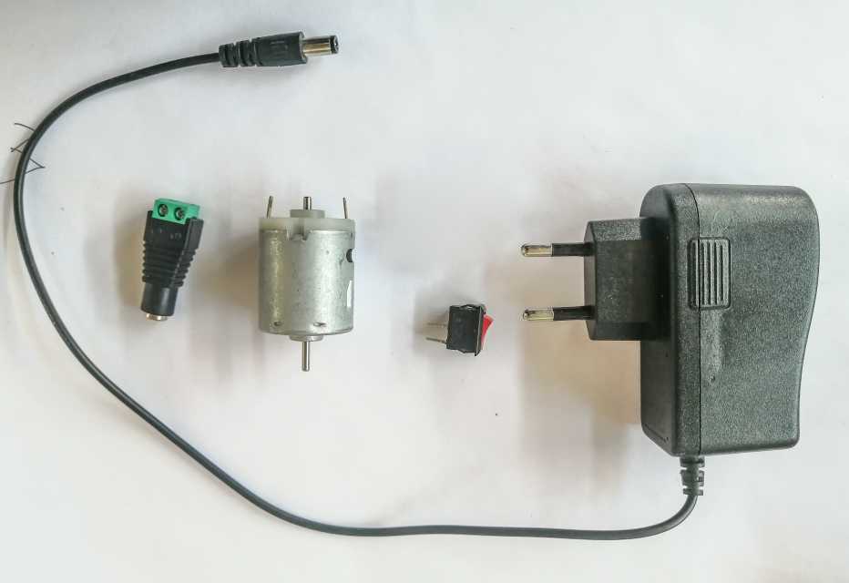
This design has very simple electronics (see diagram and photo of electronics below). It does not need programming, since it is the same system used in this project.

Below is a brief description of the electronic part used according to this documentation page.

  1. Wiring: Power comes through the barrel adapter’s positive terminal. It goes through a rocker switch — to the motor’s positive contact and from the negative contact to a microswitch’s COM terminal. Then from the normally open — or N-O terminal — it goes back to the barrel adapter’s negative terminal.
  2. Connectors: We soldered wires onto the motor, limit switch, and rocker switch. We used screw terminals and jumper wire connectors to make the design modular so we could go back in and modify, repair, and swap out motors for experimenting more easily.

To build this prototype I decide not to use a limit switch. Here's the diagram:

2.4. Manufacturing the parts(CAM)

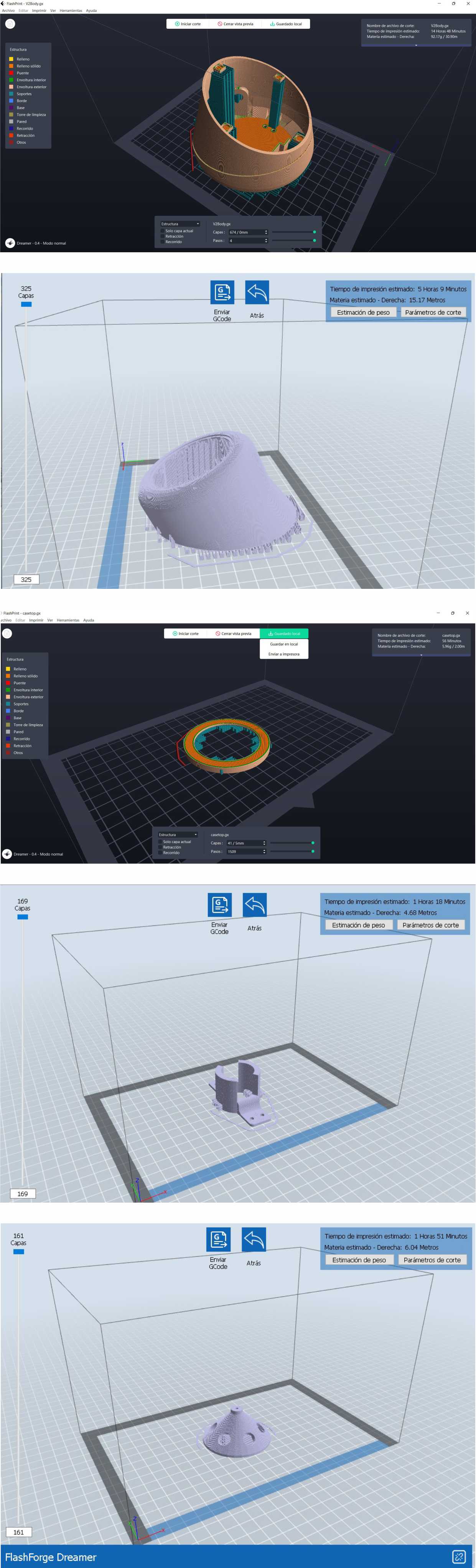
All the part that needed to be manufactured were made using 3D printing because I was looking for a great surface finishing, but also to use just one or two lab technologies, to be more easy to replicate.

The stl files can be found at the bottom of this page. All the parts for the electronics were attached and printed with the base, except the motor mount to sold the wires properly.

Parameters used:

  1. Material: PLA)
  2. Layer height: 0.2
  3. Minimum speed: 50mm/s
  4. Extruder temperature: 190°C
  5. Platform temp.: 40°C
  6. Infill: 80%
  7. Raft: No
  8. Supports: YES

Results:

Acrylic lid

The prototype has a transparent acrylic lid that allows you to see the machine running and the tubes rotating at high speed. To manufacture this piece I use laser cutting and a sheet of 2mm acrylic .

2.5. Assemble & Results:

When all the parts have been printed and the electronics ready, begin the assembly process.
The assembly was done in this order:

  1. Place the motor on the mount and solder two wires
  2. Fix the mount to the base using screws
  3. Embed the switch in the base and solder cables
  4. Place the jack adapter inside the base and solder with remaining wires.
  5. Place the tube holder
  6. Glue the acrylic cover to the top cover
  7. Stick magnets on the base and lid
  8. Done

2.5.1. BOM (Bill of materials)

2.6. Test:

To test the prototype, I follow this steps:

  1. I plugged the 12V DC adapter into the power barrel adapter of the case;
  2. Place tubes opposite one another and with relatively the same amount of contents in them.
  3. Flip the rocker switch to on
  4. Close the lid and hold it closed.
  5. Flip the swith again and wait for the rotor to stop spinning before fully opening the lid.

Prep and test:

Here are my results:

It was an intense week but I'm happy I could pull out a funtional prototype.

4. Files

  1. .Stl File
  2. Rhinoceros 7 .3dm File
  3. .dxf acrylic slid file

Weekly assignments

  • 100%
    Research and document existing fabrication methods, machines and industries, add references, tutorials and sketches of the hardware you will make
  • 100%
    Document the process of designing the files for your machine/machine-hack/tool and its fabrication including the assembly process
  • 100%
    Document the parts and how to make your tool or machine
  • 100%
    Document your BOM (Bill of materials): electronics, materials, their amount, etcetera (with references of the components)
  • 100%
    Upload your 3D model and CAM files (if any)
  • 100%
    Design, create and document a final outcome, a sample project of your process
  • 100%
    Make a small video of the machine
  • 0%
    Create an interface for controling your machine (extra credit)
Back to Top