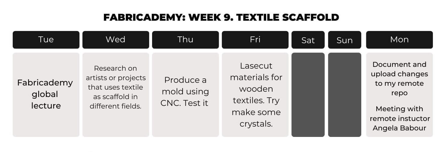
Week 09-15/11/2022

Textile
Scaffold

Scroll For More

Nov 15, 2022

Textile as Scaffold

This class focuses on exploring techniques and applications of technical textiles in the industry. It introduces the concept of designing custom processes that require the design of a set of tools, processes and workflow.


1. Weekly Documentation planning

How I worked this week

2. Inspiration and research

I found the work of OTTAN Studio, which is a circular production bussines model that protect natural resources from being depleted and raise awareness about the importance of up-cycling organic wastes in the circular economy. It has a widespread application in architecture and product design.

Decorative projects made by OTTAN studio Source.

Another project that I found is Smile Plastics. It is a materials design and manufacturing house creating hand crafted, supersized panels for retail, architecture, interiors and product design.

Saskia Pomeroy place mats. Images by Tian Khee Siong. Material: Kaleido. Source.

The research and testing into layering Linoleum flooring, laminating into blocks and shaping through sawing of Laura Jane Atkinson

Saskia Pomeroy place mats. Images by Tian Khee Siong. Material: Kaleido. Source.

I had experience using the CNC back from Fab Academy. Here's my work during the computer-controlled machining week:

My work during the Computer-controlled machining week of Fab Academy.

3. CNC Mold

3.1. CNC Machining

CNC is one of my favorite digital manufacturing technology. It's so complex yet so interesting that I love to be able to document about it. So let's start from the basics: (Huge shout-out to HUBS website. It's not only a manufacturing network, but also a learning platform that I'll be using to explain thing about CNC technology.)

What is it?

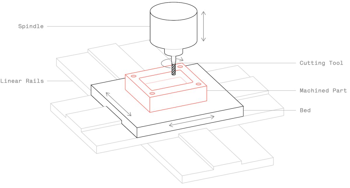
CNC (Computer Numerical Control) machining is a subtractive manufacturing technology: parts are created by removing material from a solid block (called the blank or the workpiece) using a variety of cutting tools.

Schematic of a typical CNC milling maching. Source

The two main types of CNC machining systems are milling and turning . Due to the characteristics of each machine type, milling and turning are each uniquely ideal for manufacturing different geometries.

Milling
Turning
CNC milling is the most popular CNC machine architecture. In fact, the term CNC milling is often synonymous with CNC machining. CNC milling machines use rotational cutting tools to remove material from a part mounted on the machine bed.

Most CNC milling systems have 3 linear degrees of freedom: the X, Y and Z axes. More advanced systems have 5 degrees of machining freedom via the rotation of the bed and/or the tool head (A and B axes). 5-axis machines can produce parts with high geometric complexity and may eliminate the need for multiple machine steps.

Types of CNC Machining. Source.

3-axis CNC machines

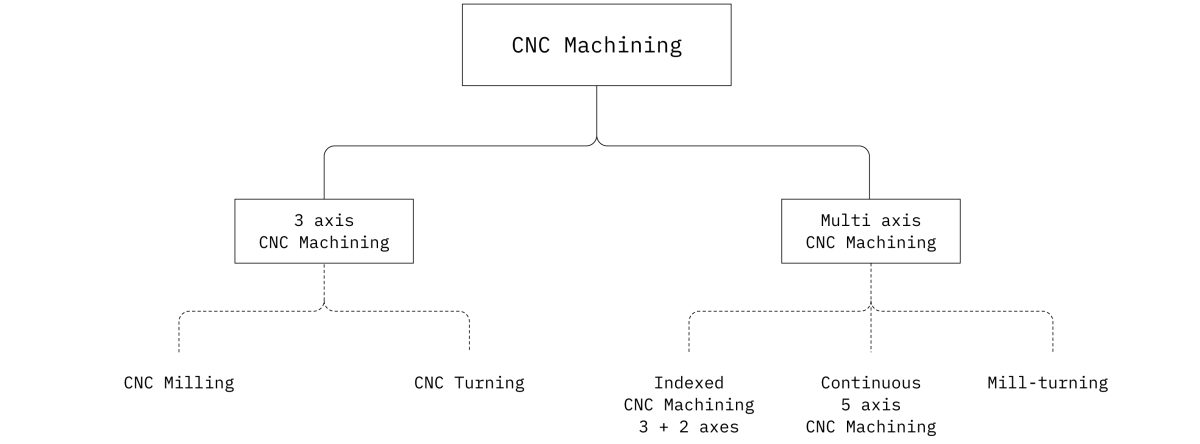
CNC milling and CNC turning machines are examples of 3-axis CNC systems. These “basic” machines allow the movement of the cutting tool in three linear axes relative to the workpiece (left-right, back-forth and up-down).

Source.

Currently, we have 2 machines availables at the Fab Lab:

3.2. Lab Machines

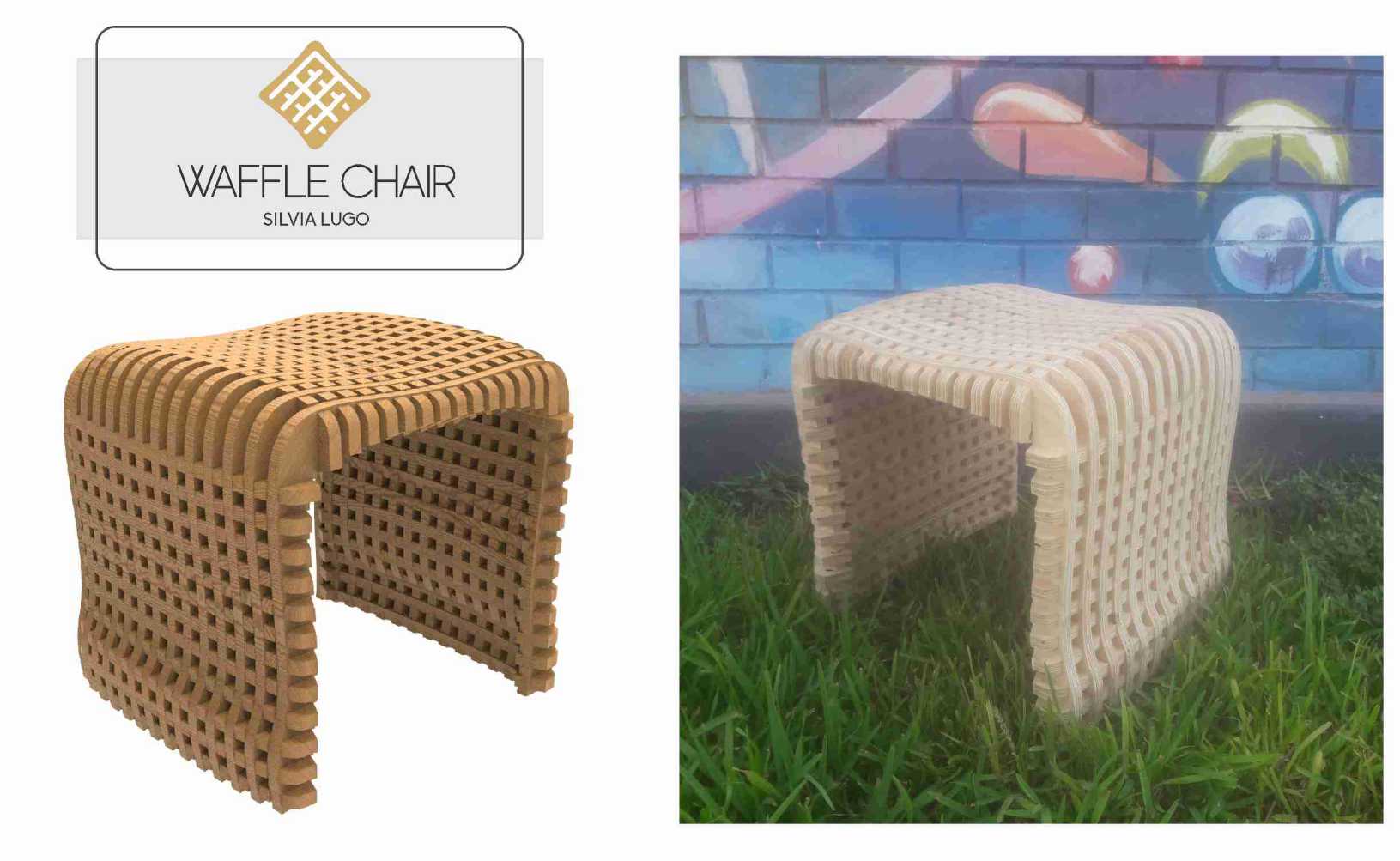
For my crafted material I decide to work with Gelatine. Gelatine is an animal derived ingredient, made from the collagen present in animal parts. it comes in various forms, such as jelly, dry thin flat sheets or powder, in almost all cases it a translucent material, which can be easily coloured.
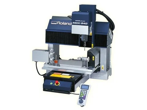
ROLAND MDX-540 Shopbot PRAlpha 120-60
Picture of a Common Anode RGB LED
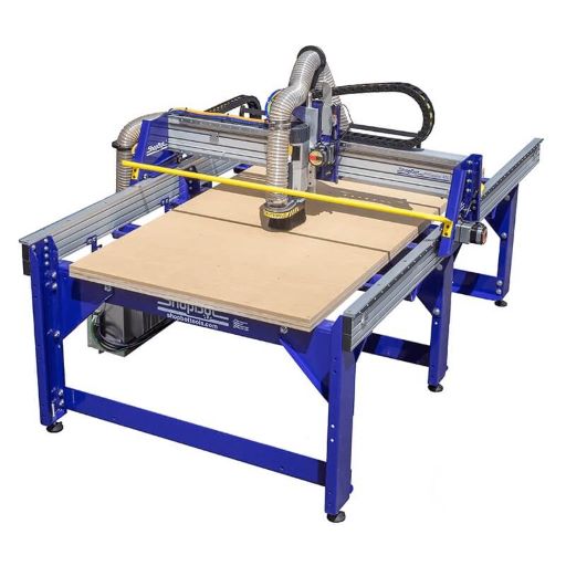
Dimensions: 500 x 400 x 155 mm from Roland. Dimensions: 3.28m x 1.55m x .2m from Shopbot.

3.3.Design

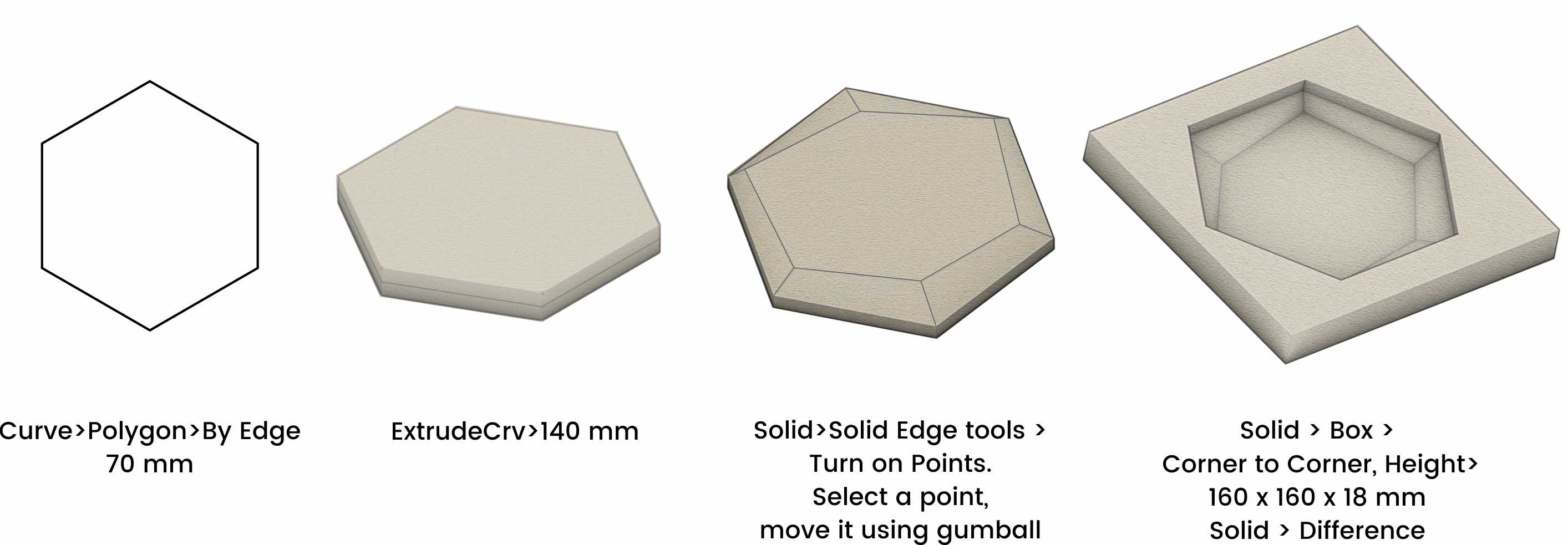
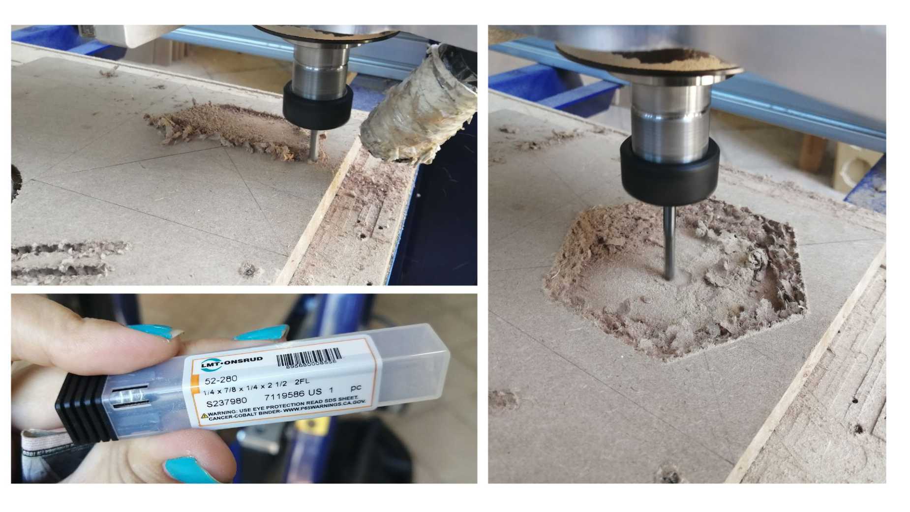
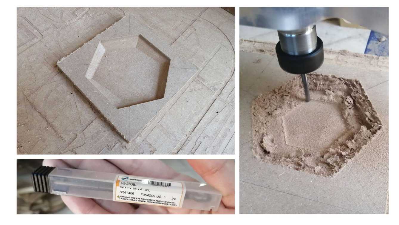
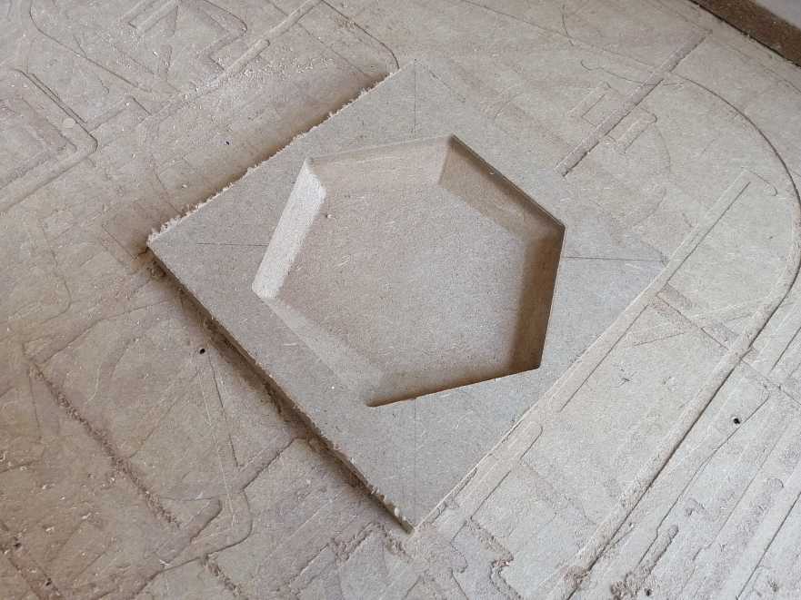
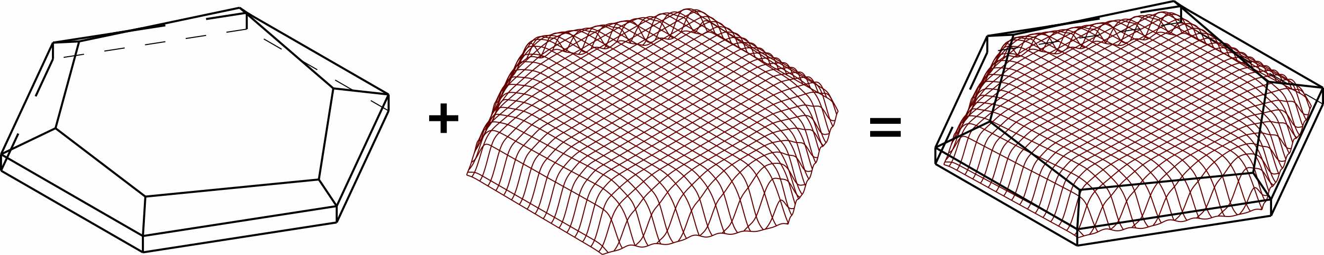
For this week I want to make some some trays for my house.I used Rhinoceros to make a simple design and the Mold. Here are the steps:

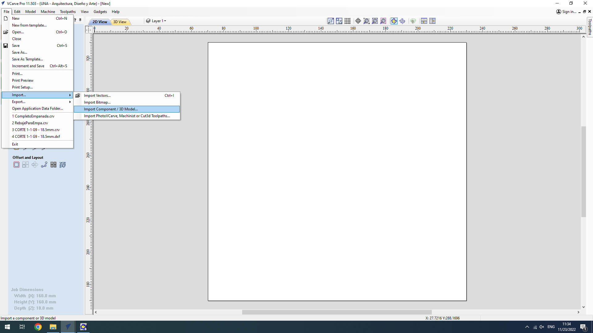
I exported the model to .stl.

3.4.G CODE: V carve pro

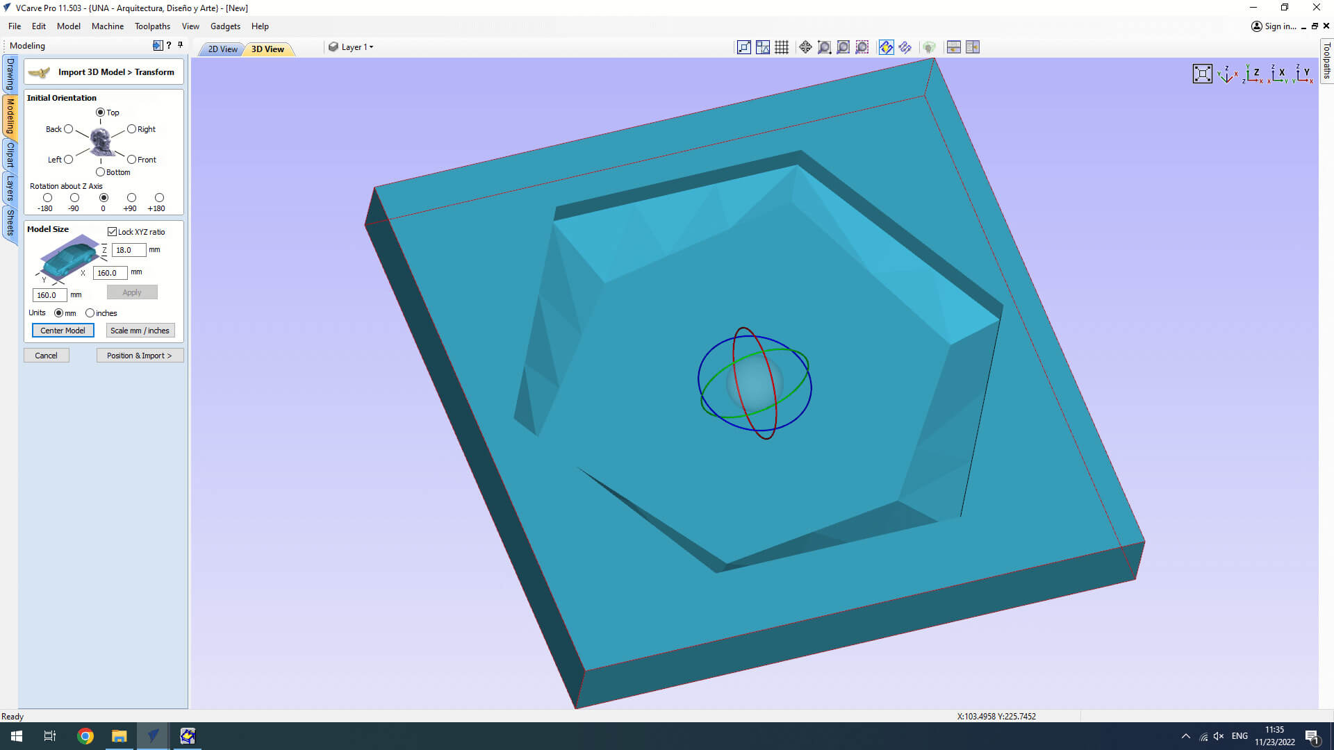
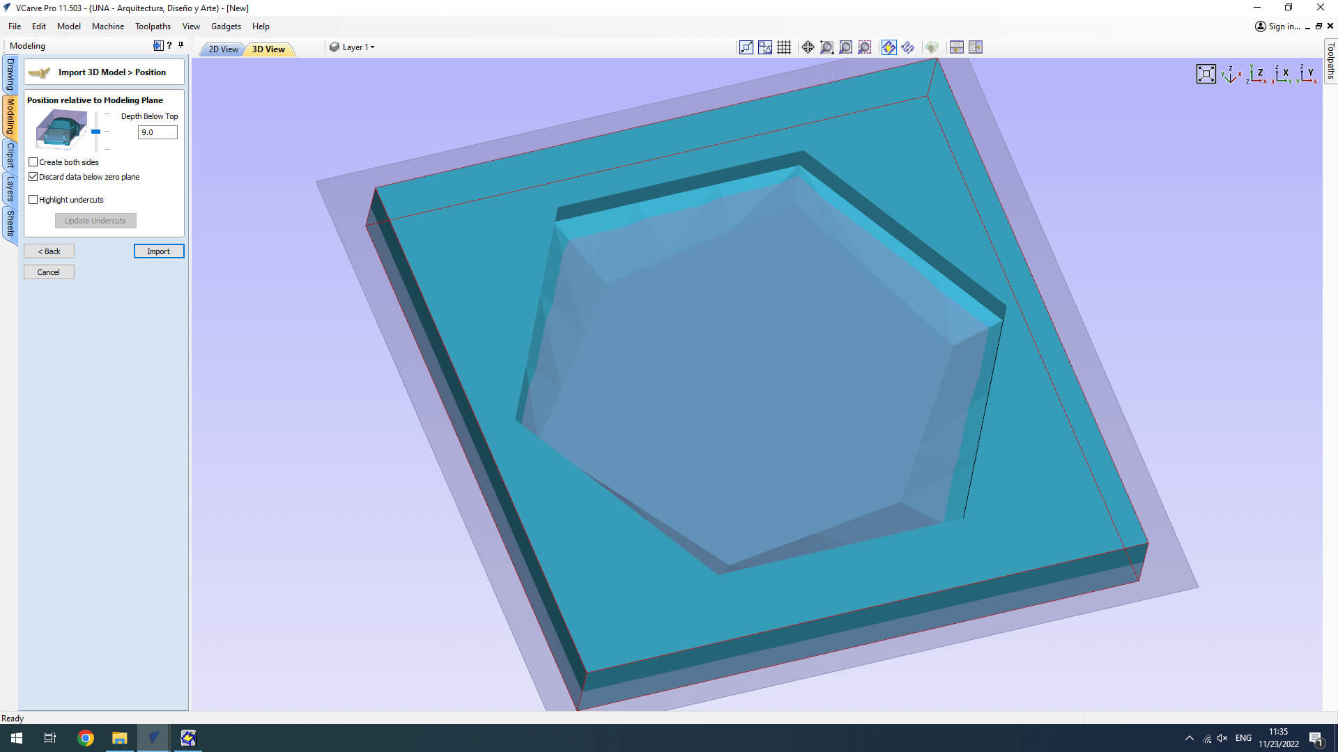
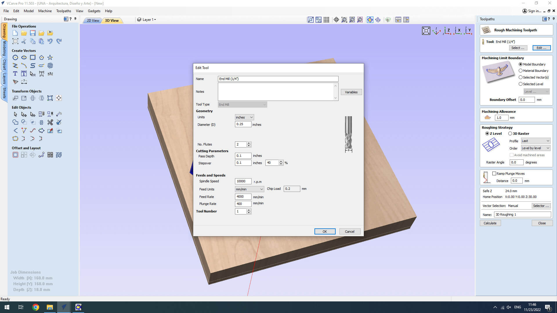
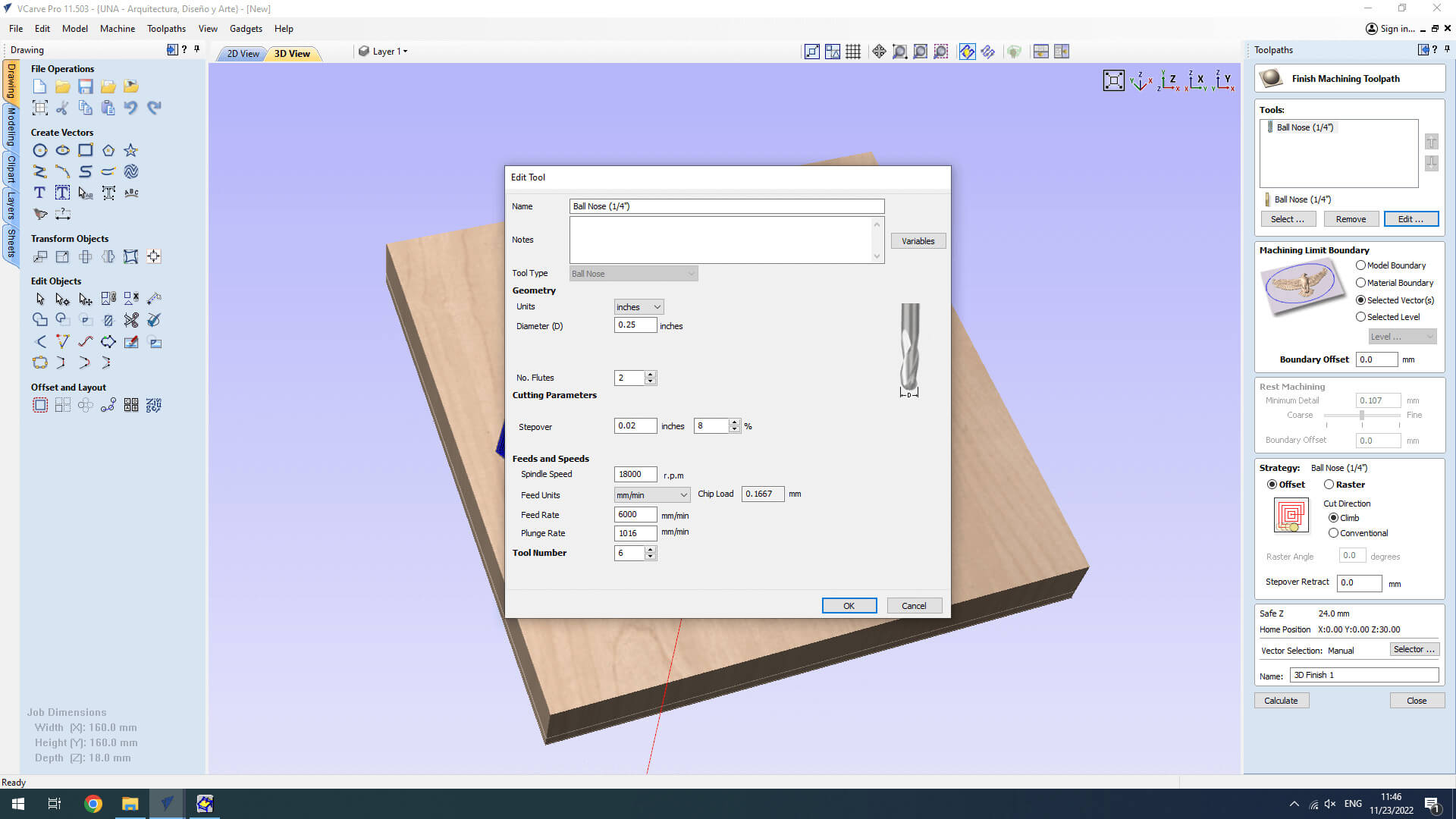
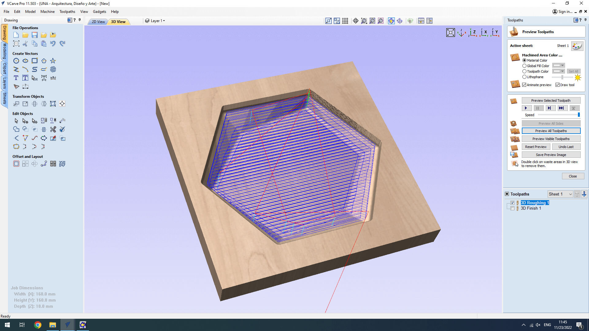
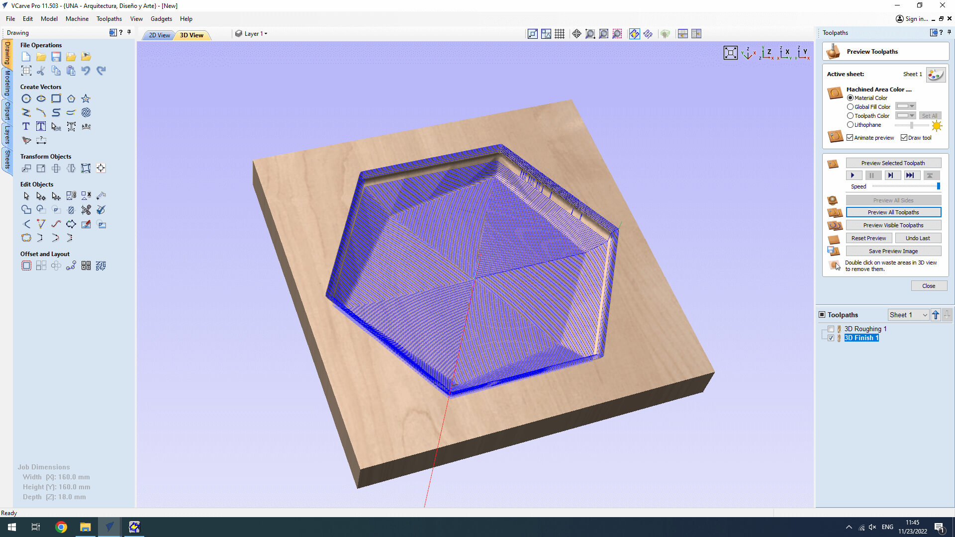
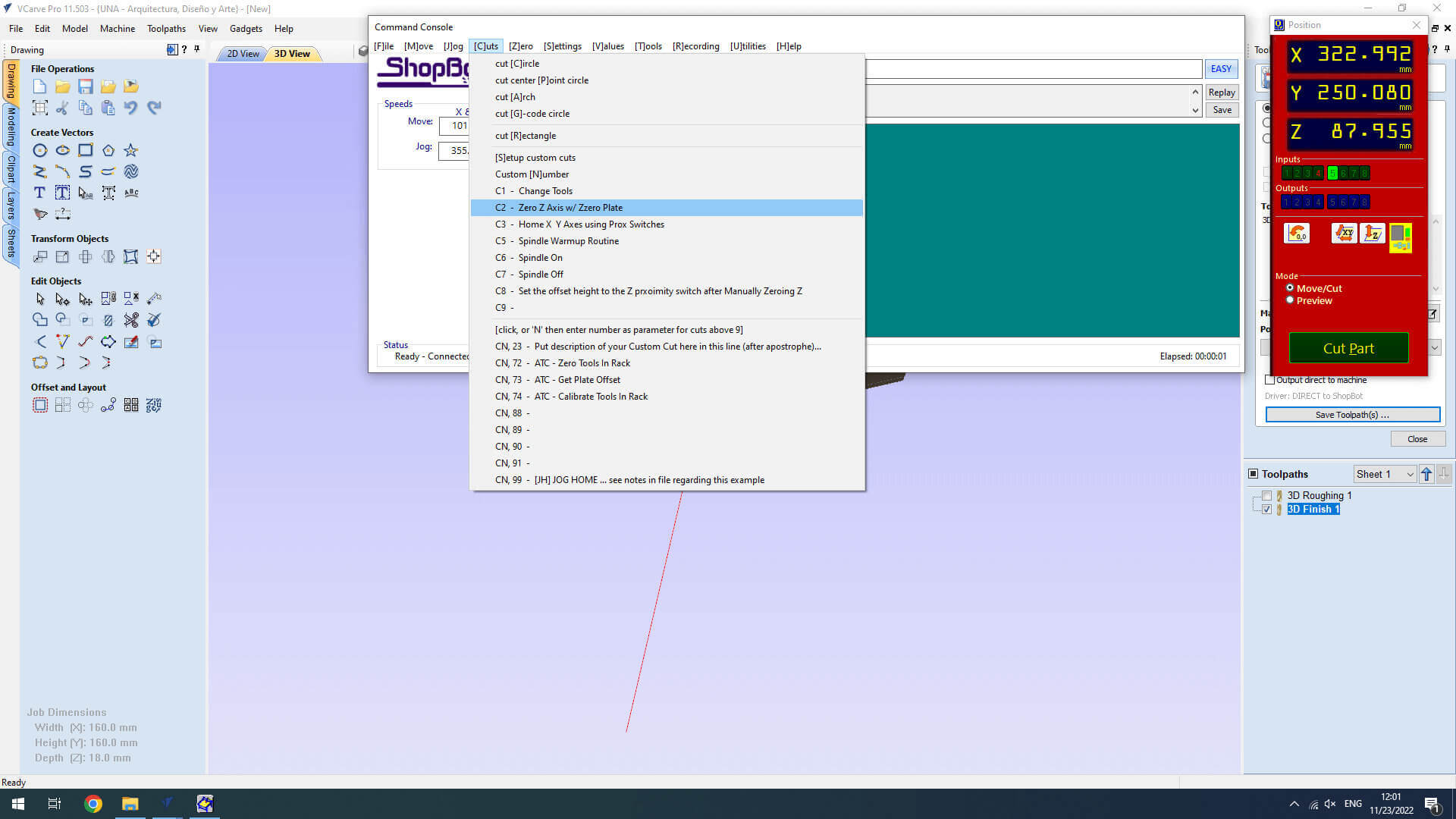
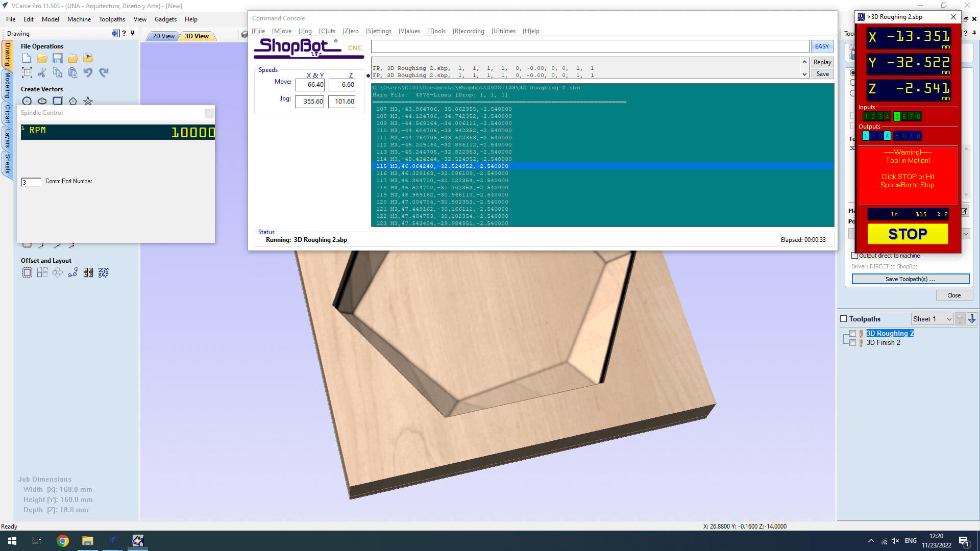
Here are the steps to use V carve pro, which is the software that our CNC use to generate G Code:

  1. Open Vcarve pro. Go to "File" > Import > Import Component / 3D Model.
  2. Set the size of the material you'll be using, and position the 3D Model
  3. We will make this job in 2 operations, Rogh and Finishing. Go to the "Toolpaths" tab at the right part of the program, select "3D Rough Machining Toolpath" this operation in machining is mainly used to remove bulk material rapidly and roughly shape the workpiece to the desired form, in order to make the subsequent processing is more convenient and efficient.
    1. Parameters:
    2. SPEED: 4.000 mm/min
    3. RPM: 10.000
    4. End mill: 1/4 (6.721 mm) with 2 flutes
    5. Plunge rate: 400 mm/min
    Click "Calculate".
  4. Go to "Toolpath" tab and select "Finishing Machining Toolpath". Finishing in machining refers to a manufacturing process that involves altering the surface of already fabricated parts or components for specific resolutions. This majorly includes removing aesthetic defects to improve a part’s appearance or to attain certain mechanical properties that enhance performance.
    1. Parameters:
    2. SPEED: 6.000 mm/min
    3. RPM: 18.000
    4. Ball nose mill: 1/4 (6.721 mm) with 2 flutes
    5. Plunge rate: 1.016 mm/min
    Click "Calculate".
  5. Simulate the toolpaths, if everything looks great, save the jobs. This is the final step before sending our job to our machine.

3.5. MILLING: Shopbot PRAlpha 120-60

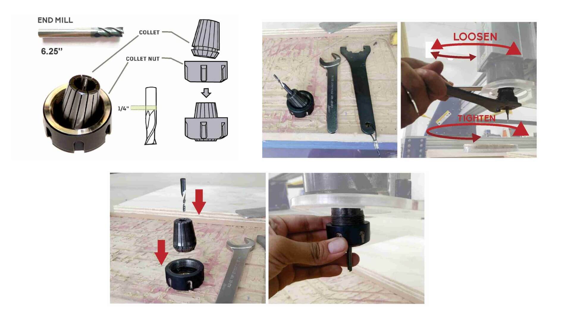
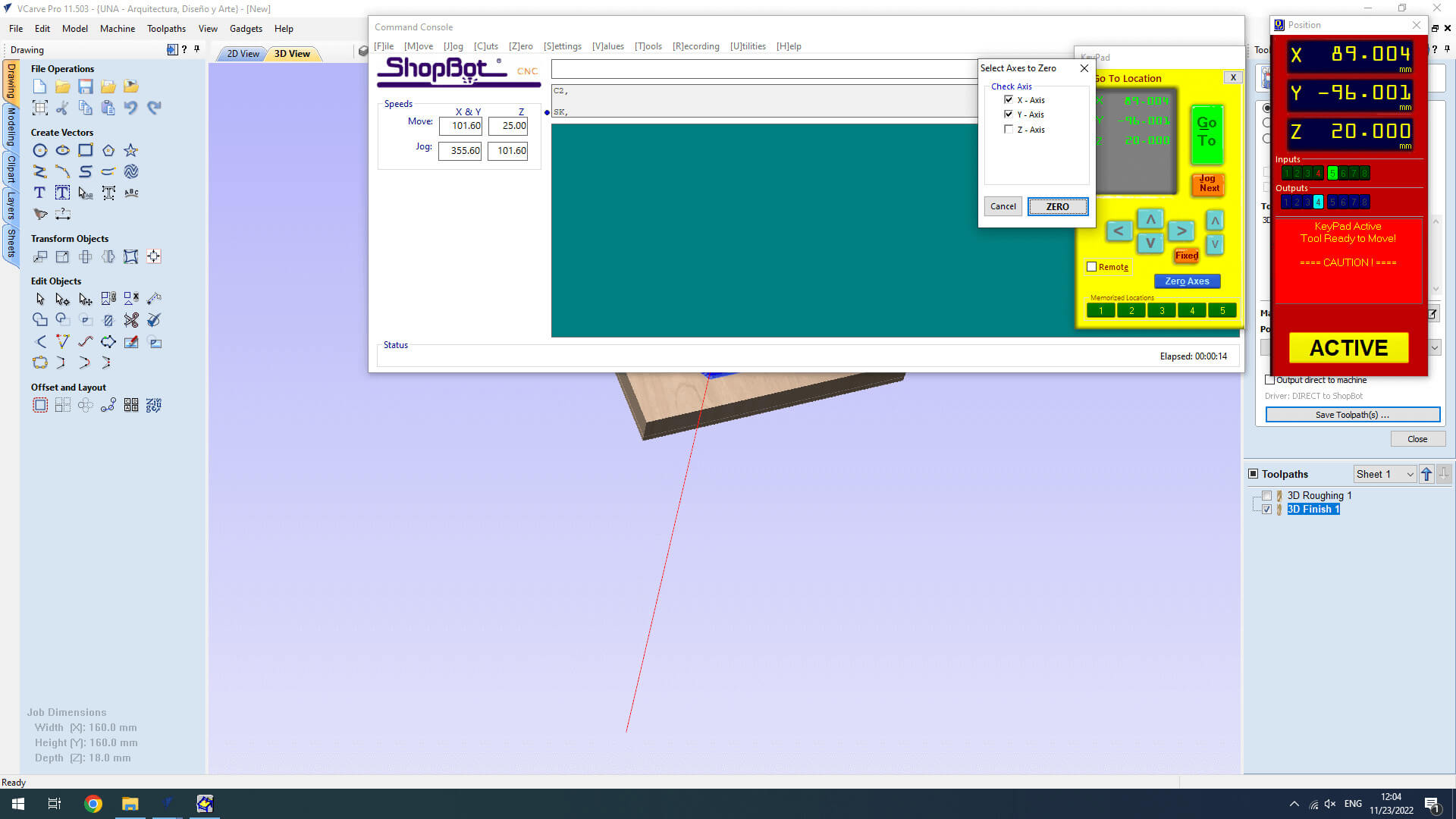
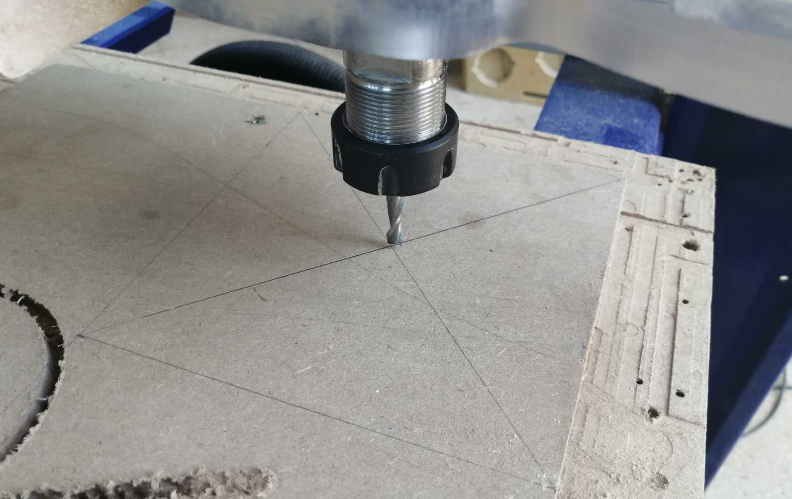
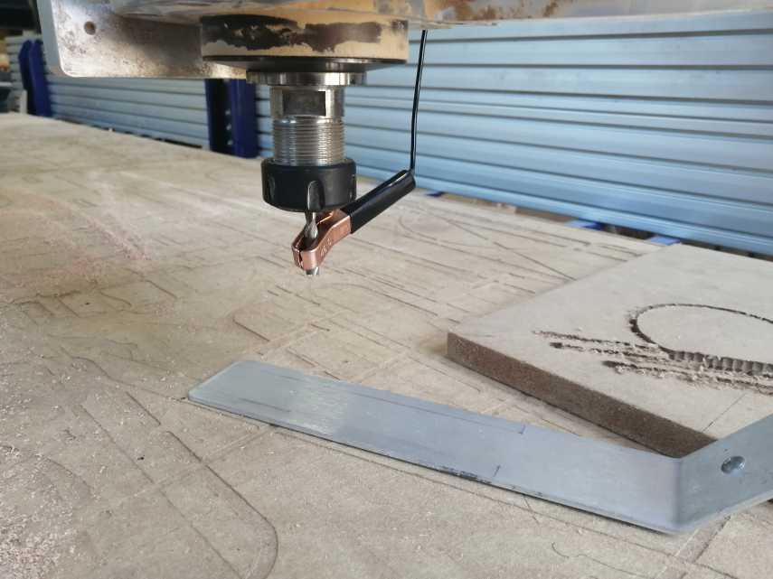
The main steps in order to use the shopbot are:

  1. Fix the material to the bed using screws.
  2. Turn on the compressor
  3. Turn on the machine and press reset button(The green one).
  4. Disengage the key that holds the wrench to change the mill. Use both wrenchs to place/change the mill. place the mill in the collet and make sure it holds it tightly.
  5. After changing the mill open shopbot3 in the computer
  6. Move the head to the origin you set using V carve
  7. Set XY origin
  8. Set Z origin using the magnetic sensor
  9. Press "cut part", select your file
  10. Press start button, then ok
  11. Mold

4. Textile composites

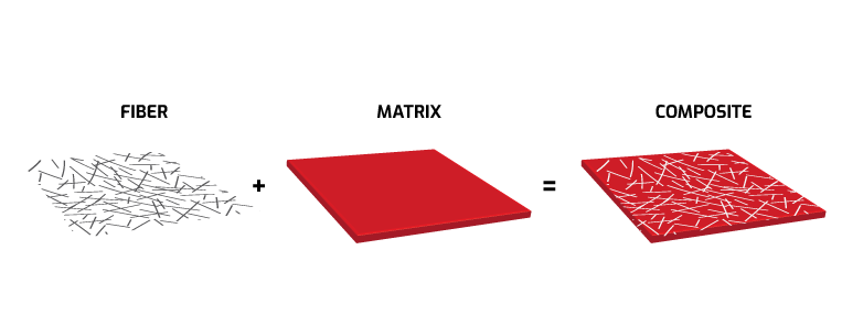
According to TWI Global a composite is "a combination of two materials with different physical and chemical properties. When they are combined they create a material which is specialised to do a certain job, for instance to become stronger, lighter or resistant to electricity. They can also improve strength and stiffness".

Composites usually has 2 materials. A matrix and a filler. After making the mold I started testing different version of composites combining textile + liquid plastic. Here are some of my test

Source

4.1. Test 1: Shredded textile

Composite type

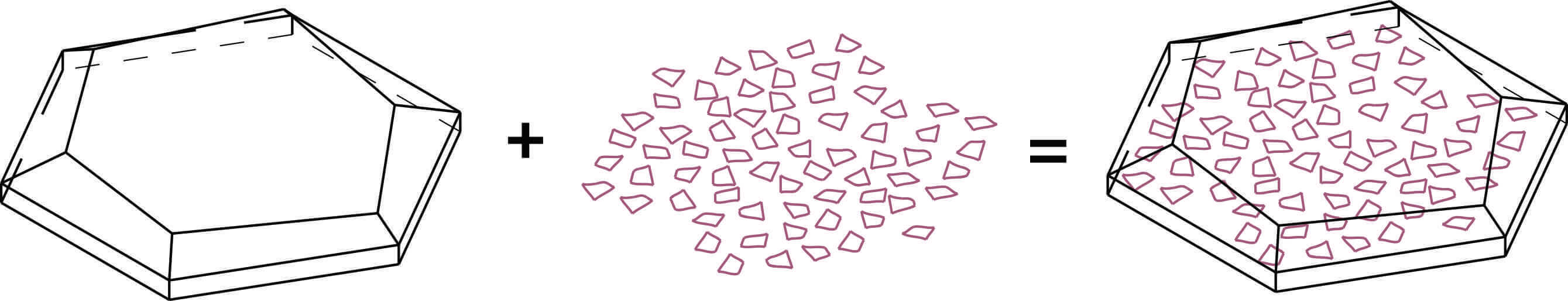
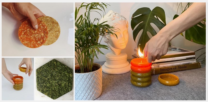
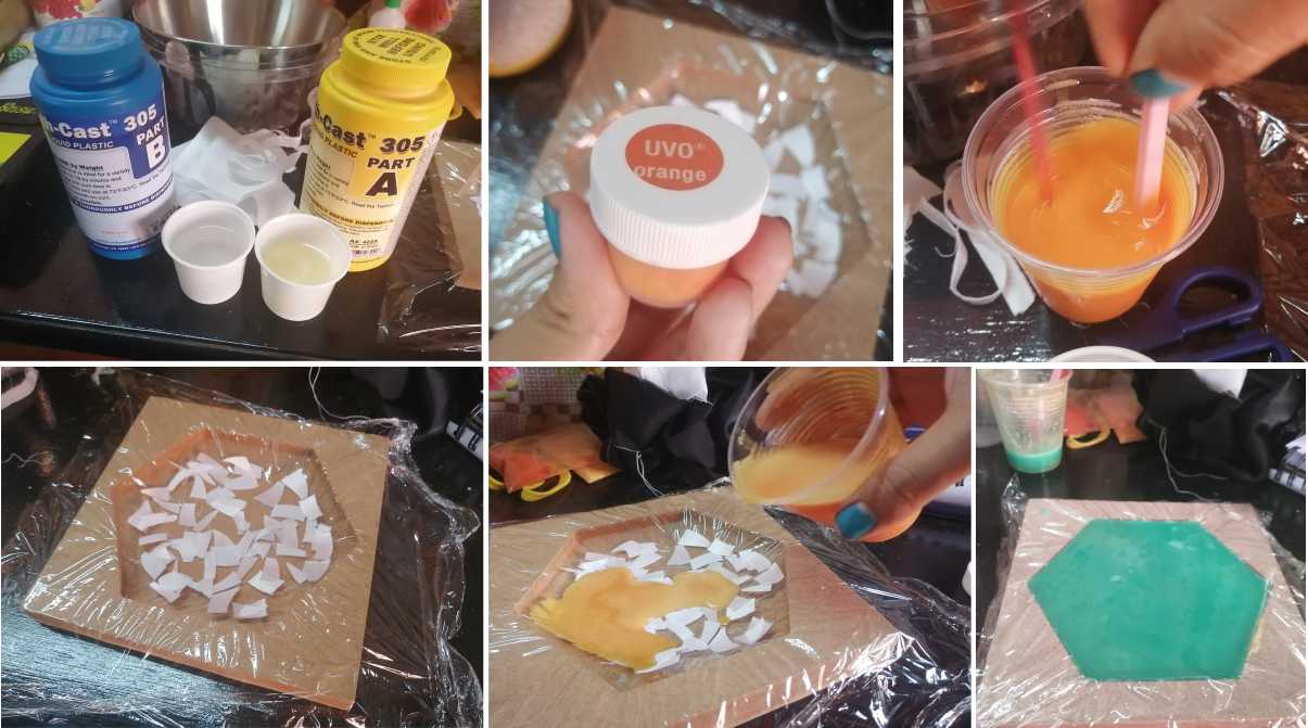
I cut up a piece of fabric into tiny pieces as the filler. The liquid plastic has two components (A,B) that you have to mix and pour in the mold. It's a fast dry reaction and you can combine it with different colors. I mix the fabric and the reaction and put it in the mold for 30 minutes. Here are pictures of my result:

Process
Result

Test 2:Layers of textiles

Composite type

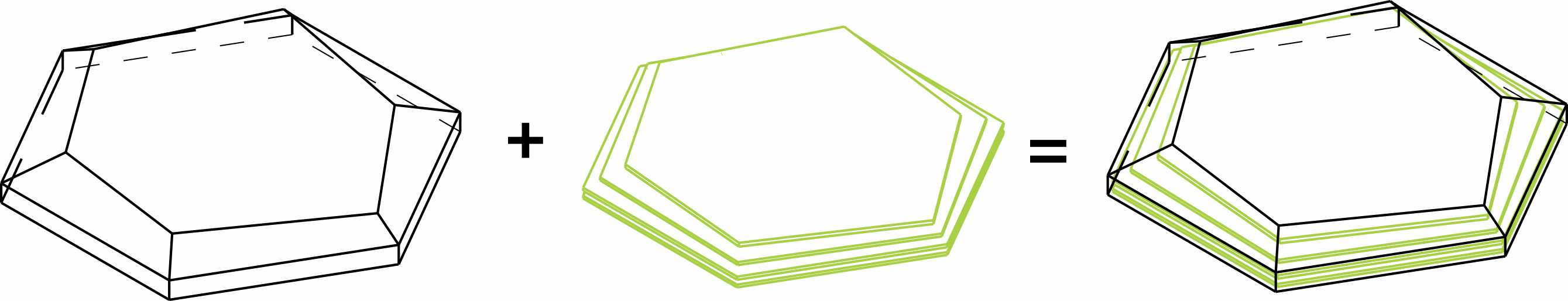
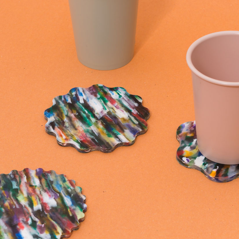
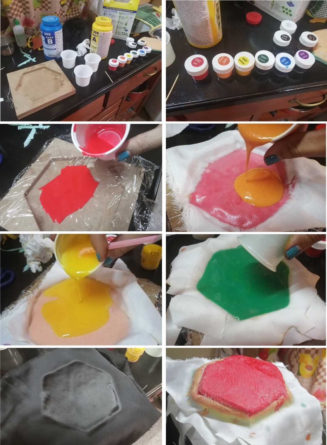
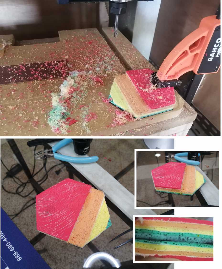
For the second test I wanted to try different colors and add the fabric in layers like a cake. Here are photos of my process and the result:

Process

So that the colors can be appreciated better, I fixed the mold to the CNC and ran a simple program. Heres's the result:

Result

Test 3:Textile Drape

Composite type

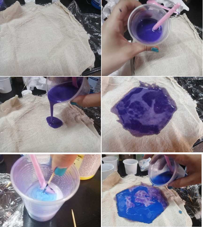
For my thirs test, I decide to use a piece of fabric without cutting it. Here are pictures of my process and my result:

Process
Result

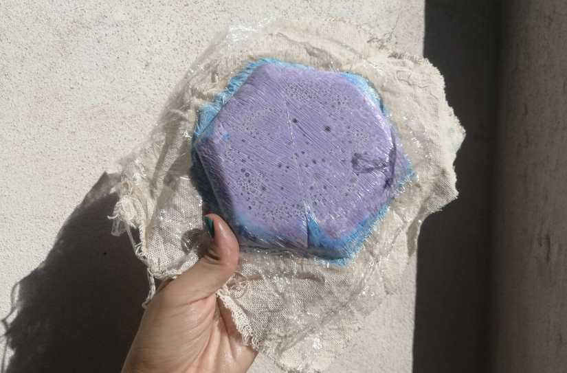
At the end I was really satisfied with my results. I think the combination of Layers and plastic was the best looking of all. It was a fun experiment.

5. Wood-textiles composite

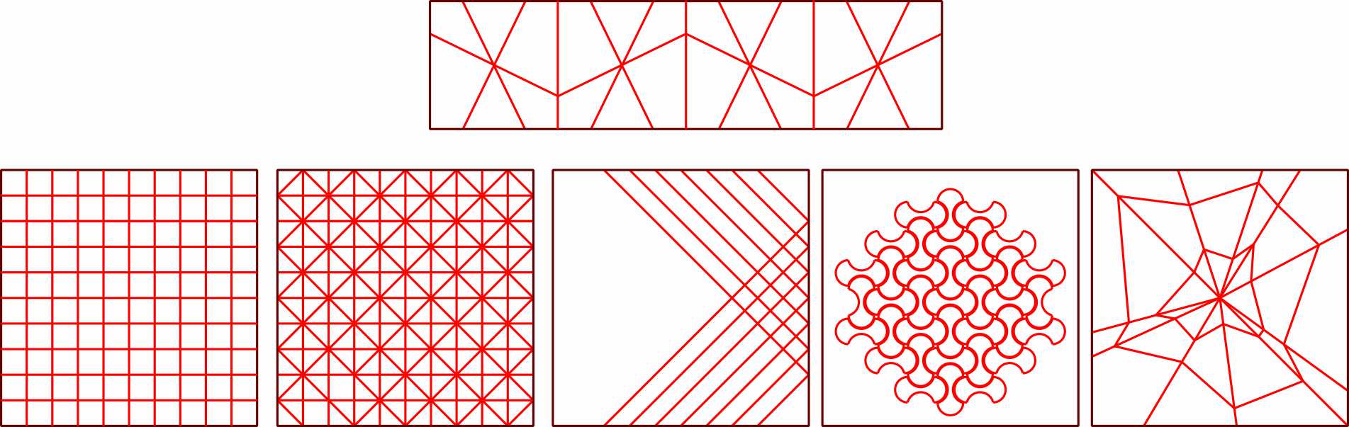
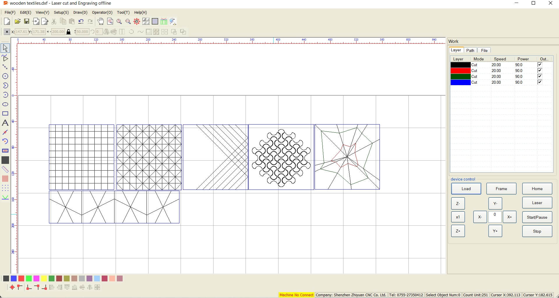
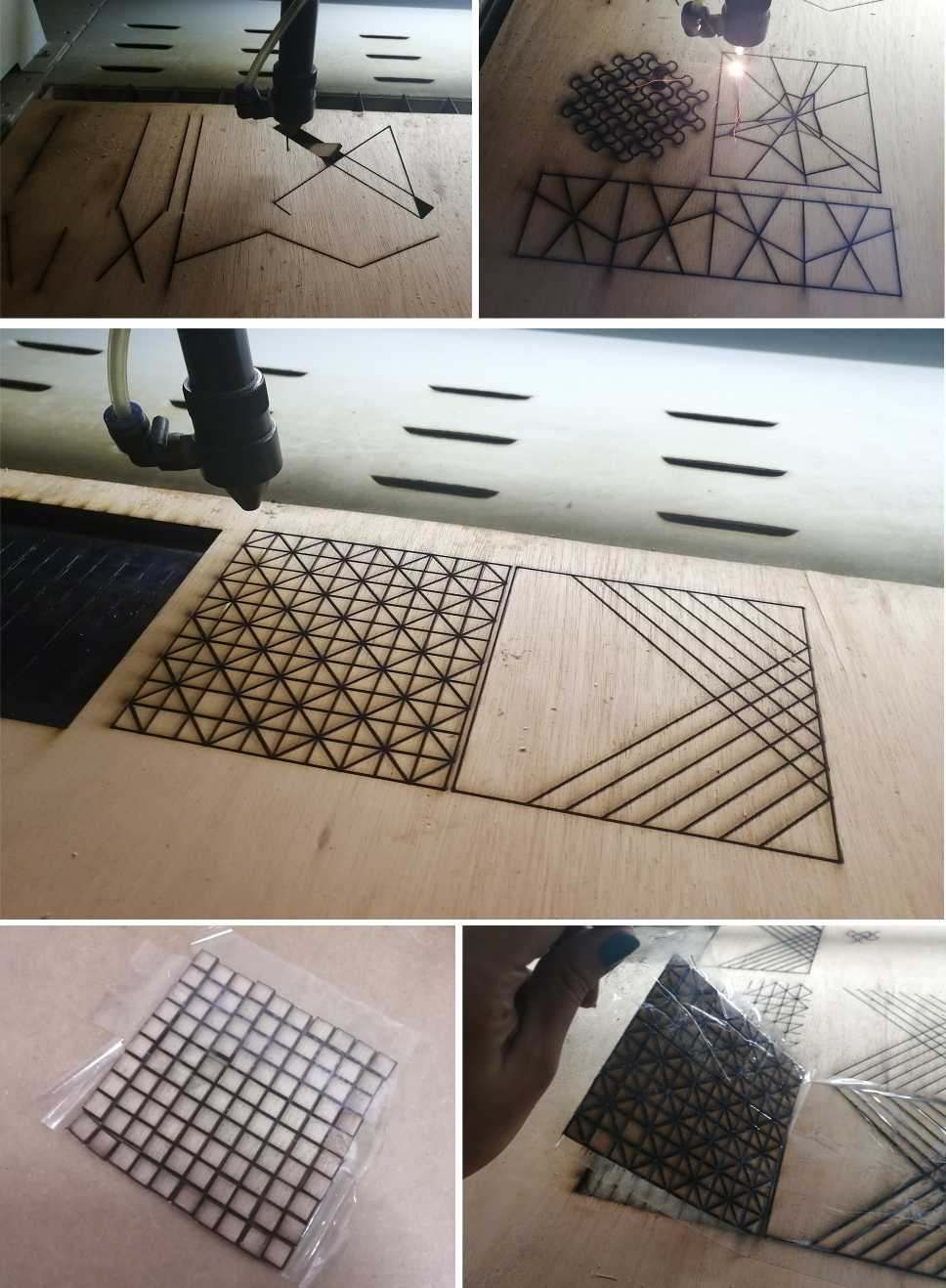
According to Material District wood textiles consists of "a combination of wood veneer and textile. Thanks to the geometric surface finishing of the wood, it becomes flexible, more or less so depending on the size of the shapes. Various combinations of wood and textile combine the hard panel formation of wood with the pliability and folding of textiles."

5.1. Design

Using Rhinoceros I prepare some designs:

Random Designs

5.2. Fabrication:

5.3. Results:

6. Crystallization: Salt Crystals

Here's a simulation I made on blender( 3D modeling software ) to show my idea.

6.1. How do salt crystals form?

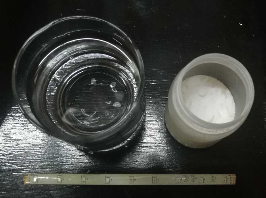
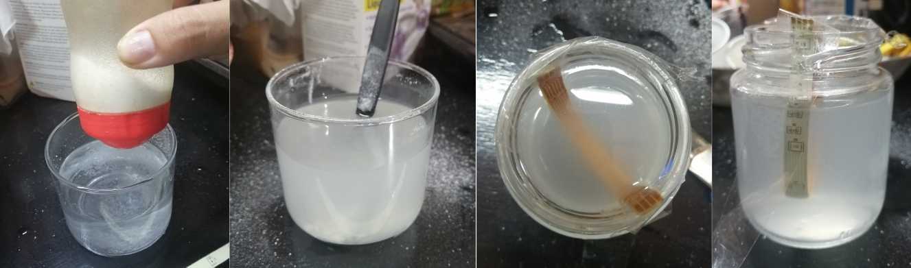
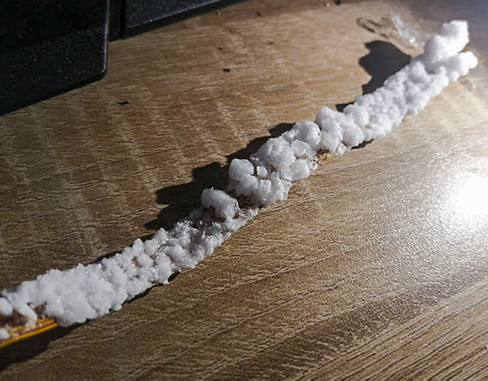
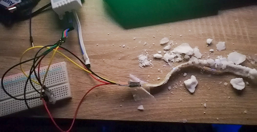
According to this website "Salt crystals form out of a “supersaturated solution”. A supersaturated solution is a solution (or mixture) that contains more solute (salt, in this case) than is capable of being dissolved in the solvent (water).
The water molecules speed up as they are heated, creating space between them for more salt to be absorbed than usual. As the water cools and evaporates, the salt comes out of the solution and forms crystals in a process known as “recrystallization”.

I decide to experiment with crystallization and electronics. I follow this tutorial ans this recipe:

6.2. Materials:

  1. 1/4 cup Sea salt (non-iodized)
  2. 1-1/2 cups Boiling water
  3. RGB LED Strip

6.3. Equipment:

  1. Measuring cup
  2. Jar
  3. Spoon

6.4. Instructions:

  1. Cut the LED Strip.
  2. Place the strip on a jar
  3. Make the supersaturated solution: Add 1/4 cup sea salt to 1-1/2 cups boiling water. Stir well to ensure as much salt as possible is dissolved into the water.
  4. If all the salt is dissolved keep adding more salt, 1 tablespoon at a time. Stir well and keep adding salt until no more can be dissolved.(You can stop adding salt when you can see undissolved granules in the bottom of the measuring cup.)
  5. Pour the supersaturated solution over the RGB LED Strip.
  6. Leave the jar in an undisturbed area and wait for the crystals to grow.
  7. You should have full crystal growth after 5-6 days.

6.5. Result:

7. Files

Textiles Composite

  1. .stl Mold Design
  2. .stl Shape
  3. Rhino file

Wooden textiles

  1. Rhino file
  2. .dxf Files

8 Reflections

What went wrong

  • I couldn't try other crystallization recipes because I didn't have the materials locally available.
  • I did not went wrong but it's important to know, crystal take time to make so you should start with that part of the assignment and then move to the other parts.
  • The final pieces obtained from the mold had a texture

What went right

  • Developing experiments with crystallization allowed me to understand the process of crystal formation and the different possibilities of application in different fields, applying it in electronics was very fun and interesting.
  • Developing wooden textiles taught me how you can alter the behavior of a soft material like textile and a rigid material like wood.
  • The developed molds turned out well and allowed me to study various forms of association of textiles and liquid plastic.

9. References:

HUBS- CNC Machining guide

Weekly assignments

  • 100%
    Include some inspiration
  • 100%
    Produce 2 techniques of textile scaffold.
  • 100%
    Document the process from CAD to CAM, the step-by-step instructions for CNC milling, mold making, vaccum forming and textile composites
  • 100%
    Upload your design and fabrication files, including the 3D model and CAM file
  • 100%
    Make a stop motion of your crystal growth or use 3D modeling software to simulate your design (extra credit)
Back to Top