Week 08-08/11/2022
Nov 8, 2022
This class focuses on creating wearable electronic projects using Arduino and Attiny.
1. Weekly Documentation planning
2.Inspiration and research
3. Actuator swatches

I had experience with attiny and pcb milling thanks to Fab Academy, I milled, soldered and programmed many different pcbs, but I never explore the soft side of circuit making.
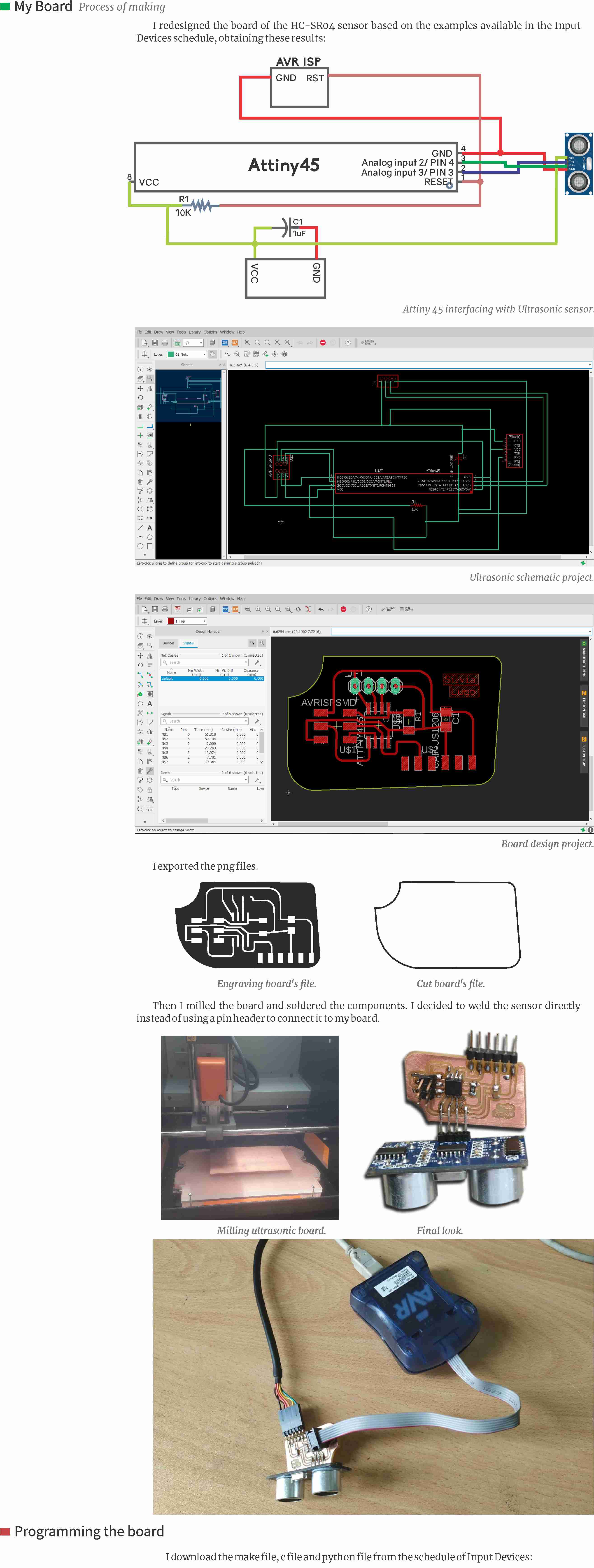
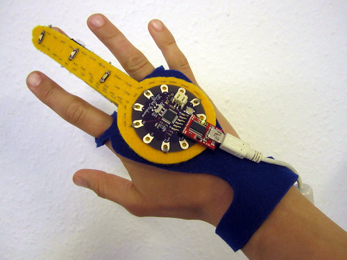
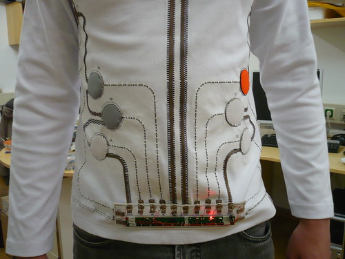
During the first part of this week, I looked for inspiration in other people's work with soft sensors ans circuit applied to wearables. I find the amazing page of Kobakant, full of tutorials and example projects of different designers which were really inspiring for this week. Their KOBAKANT DIY wearable technology documentation was a comprehensible and accessible reference resource for my week. Here are some examples that I founf in that page:

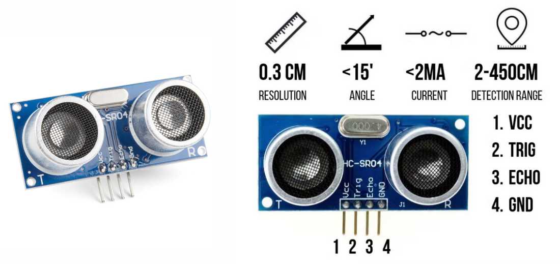
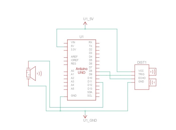
For my first actuator I decided to use the HC-SR04 ultrasonic sensor, it's a common component used in many arduino projects. I had experience working with it and I'll be referencing this blog to talk a little bit about it.
According to HowtoMechatronics.com the HC-SR04 is an affordable and easy to use distance measuring sensor which has a range from 2cm to 400cm (about an inch to 13 feet).
The sensor is composed of two ultrasonic transducers. One is transmitter which outputs ultrasonic sound pulses and the other is receiver which listens for reflected waves. Here are its main specifications:
| Operating Voltage | 5V DC |
| Operating Current | 15mA |
| Operating Frequency | 40KHz |
| Min Range | 2cm / 1 inch |
| Max Range | 400cm / 13 feet |
| Accuracy | 3mm |
| Measuring Angle | <15° |
| Dimension | 45 x 20 x 15mm |
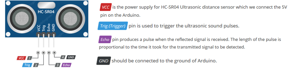
The sensor has 4 pins. VCC and GND go to 5V and GND pins on the Arduino, and the Trig and Echo go to any digital Arduino pin. Using the Trig pin we send the ultrasound wave from the transmitter, and with the Echo pin we listen for the reflected signal.
It emits an ultrasound at 40 000 Hz which travels through the air and if there is an object or obstacle on its path It will bounce back to the module. Considering the travel time and the speed of the sound you can calculate the distance, using the following basic formula for calculating distance:
Distance = Speed x Time
In order to generate the ultrasound we need to set the Trig pin on a High State for 10 µs. That will send out an 8 cycle ultrasonic burst which will travel at the speed of sound. The Echo pins goes high right away after that 8 cycle ultrasonic burst is sent, and it starts listening or waiting for that wave to be reflected from an object.
If there is no object or reflected pulse, the Echo pin will time-out after 38ms and get back to low state.If we receive a reflected pulse, the Echo pin will go down sooner than those 38ms. According to the amount of time the Echo pin was HIGH, we can determine the distance the sound wave traveled, thus the distance from the sensor to the object.
Distance = Speed x Time
We actually know both the speed and the time values. The time is the amount of time the Echo pin was HIGH, and the speed is the speed of sound which is 340m/s. There’s one additional step we need to do, and that’s divide the end result by 2. and that’s because we are measuring the duration the sound wave needs to travel to the object and bounce back.
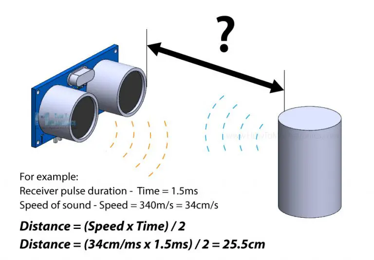
Let’s say the Echo pin was HIGH for 2ms. If we want the get the distance result in cm, we can convert the speed of sound value from 340m/s to 34cm/ms.
Distance = (Speed x Time) / 2 = (34cm/ms x 1.5ms) / 2 = 25.5cm.
According to Physical Computing There are two primary types of buzzers: magnetic and piezo. A magnetic buzzer operates similarly to a traditional speaker: a current driven through a coil of wire produces a magnetic field, which dynamically moves a magnetic disk resulting in a sound wave. In contrast, a piezo buzzer is driven by voltage rather than current and is constructed out of piezoelectric material. This material mechanically deforms in response to applied voltages, which can be used to generate sounds.
There are two types of piezo buzzers: active and passive. Active buzzers use internal oscillators to generate tones, so only need a steady DC voltage. In contrast, passive buzzers require a voltage waveform—the waveform frequency will corresopndingly vibrate the piezoelectric material to make sound. This is the waveform that our Arduino will produce via tone.
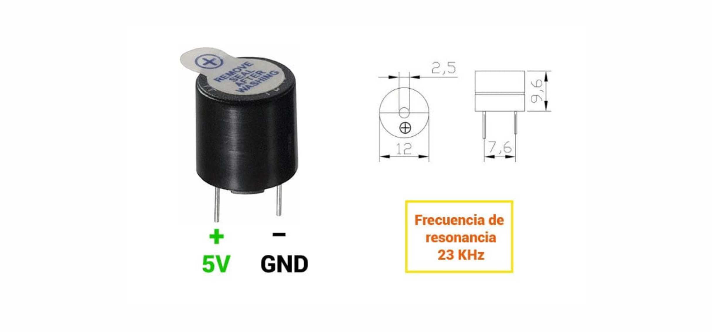
If generating a square wave of the specified frequency (and 50% duty cycle) on the positive pin, the piezo buzzer generates tones. The different frequency makes a different tone. By changing the frequency of the signal on the positive pin, we can create the melody of a song.
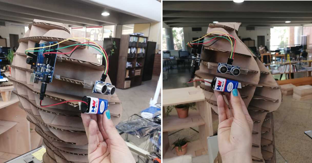
The idea behing the project is to use the ultrasonic sensor and an actuator that produce some sort of signal that will alert an user, which is a person with compromised vision, about his surroundings and how close he is to something, It is going to be located specifically in areas that are critical and usually problematic in order to help the user navigate with greater comfort and confidence.
My original idea was to combine the ultrasonic sensor with a haptic motor to produce vibration everytime you are getting close to an object or a wall, but I didn't have one at the time, so I decided to use a Buzzer. But the haptic motor one could be a 2.0 version of this prototype.

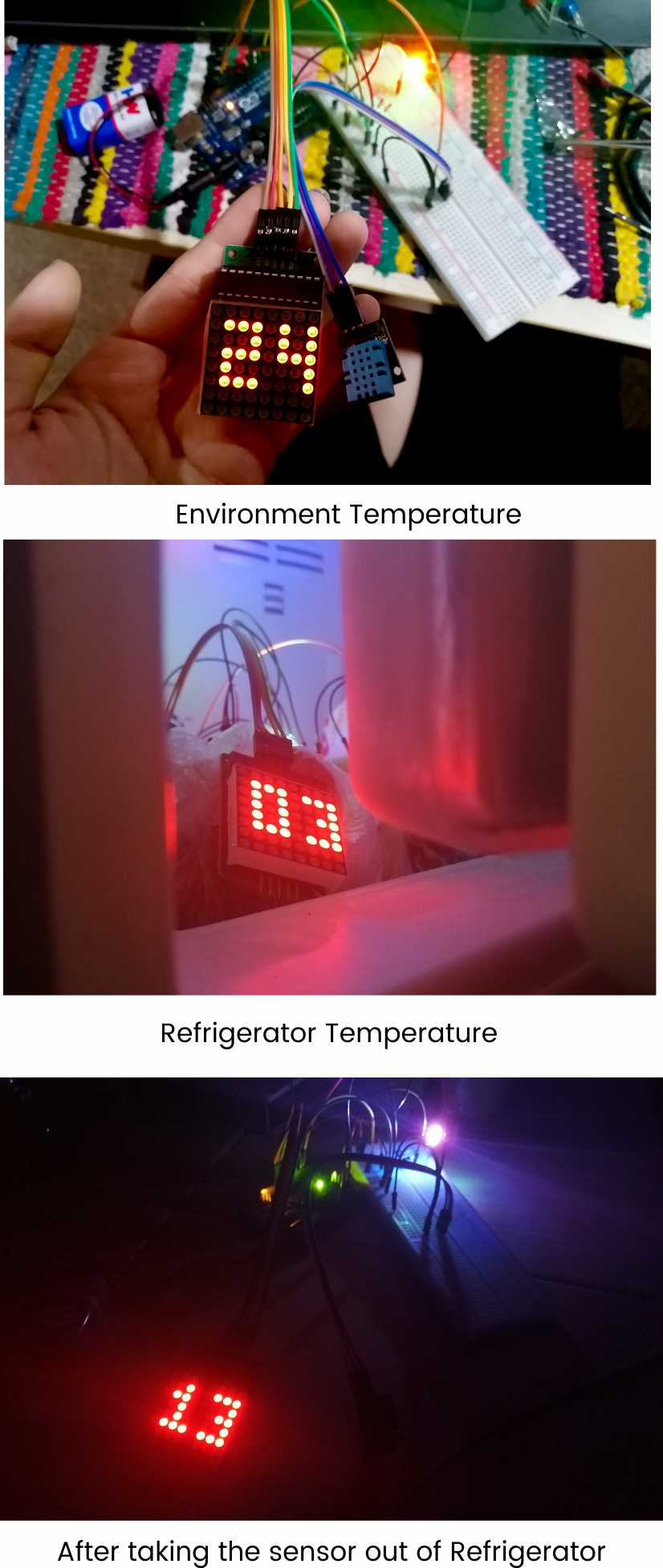
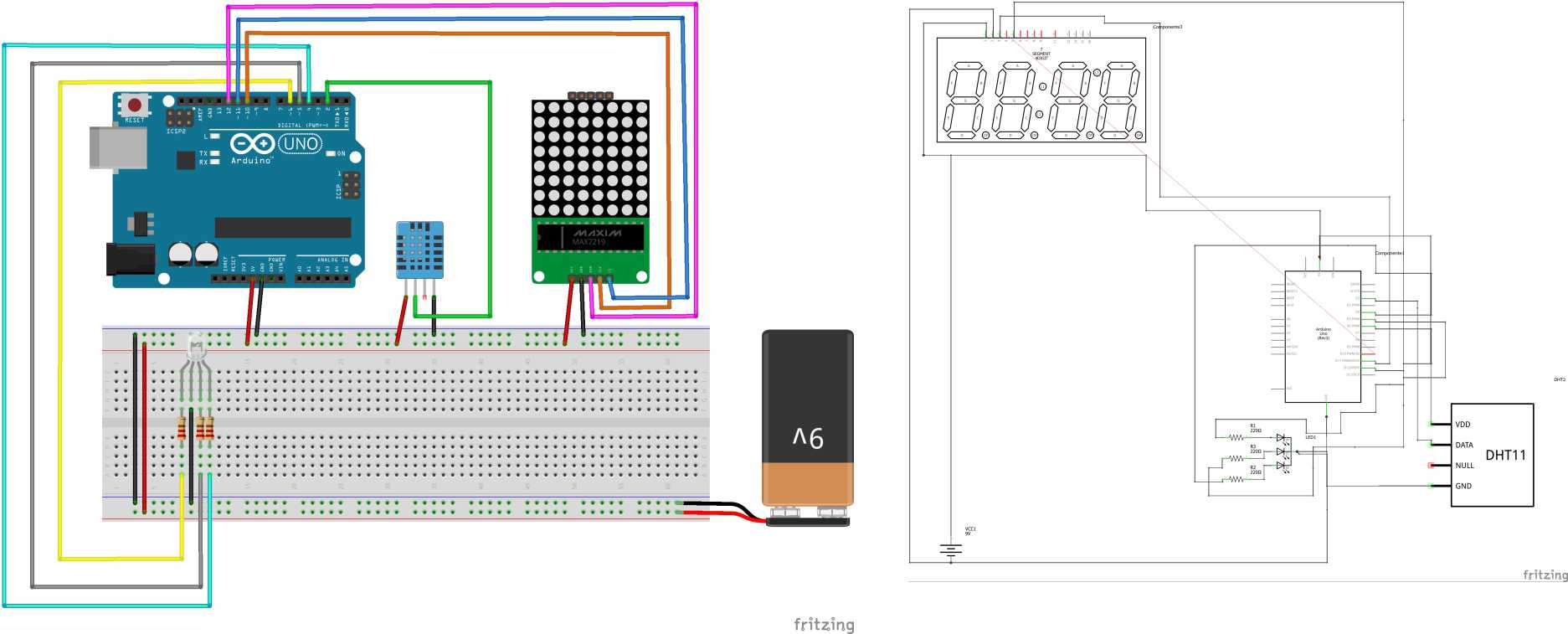
The DHT11 is a basic, ultra low-cost digital temperature and humidity sensor. It uses a capacitive humidity sensor and a thermistor to measure the surrounding air and spits out a digital signal on the data pin (no analog input pins needed). It's fairly simple to use but requires careful timing to grab data. The only real downside of this sensor is you can only get new data from it once every 2 seconds, so when using our library, sensor readings can be up to 2 seconds old.
According to Physical Computing, RGB stands for Red, Green, Blue. It is use to flash through a sequence of colors and learn about the difference between a Common Anode and Common Cathode RGB LED design.
There are two types of RGB LEDs—described below—so make sure you determine which type of RGB LED you are using as it will affect how you configure your circuit. But don’t worry, we’ll walk through both RGB LED types.
While capable of displaying thousands of color combinations, RGB LEDs are actually quite simple; they contain three separate LEDs in one package: red, green, and blue. Importantly but somewhat confusingly, there are two RGB LED designs—the Common Anode and the Common Cathode—which differ in the leg shared between the three embedded LEDs.
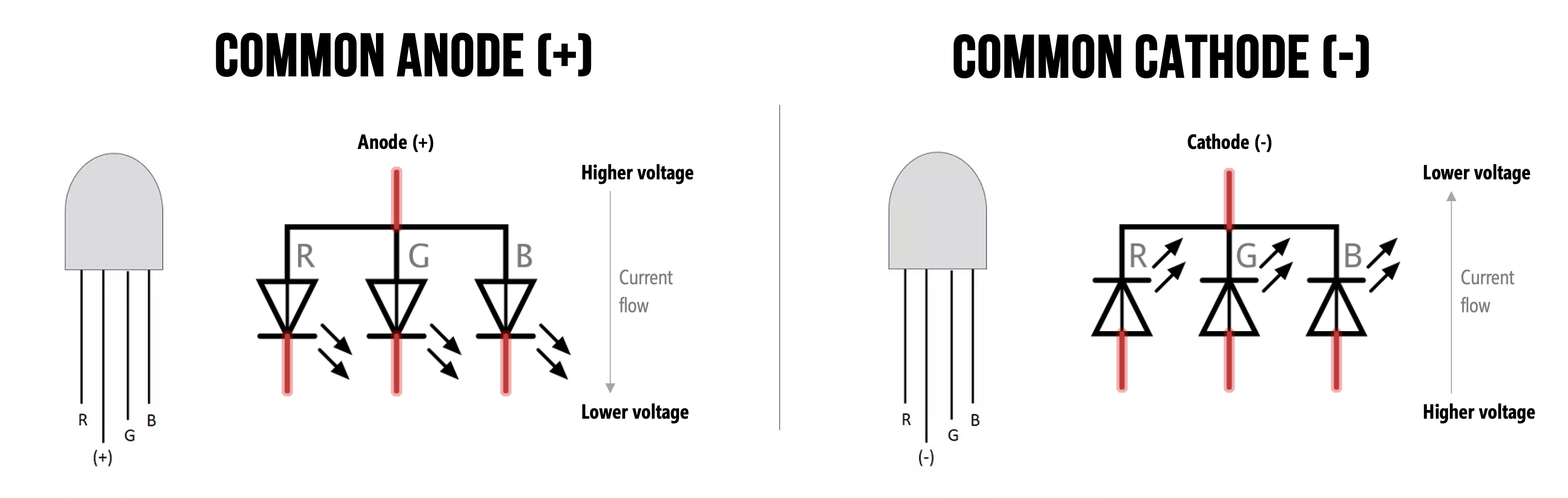
| Common Anode | Common Cathode |
|---|---|
 | 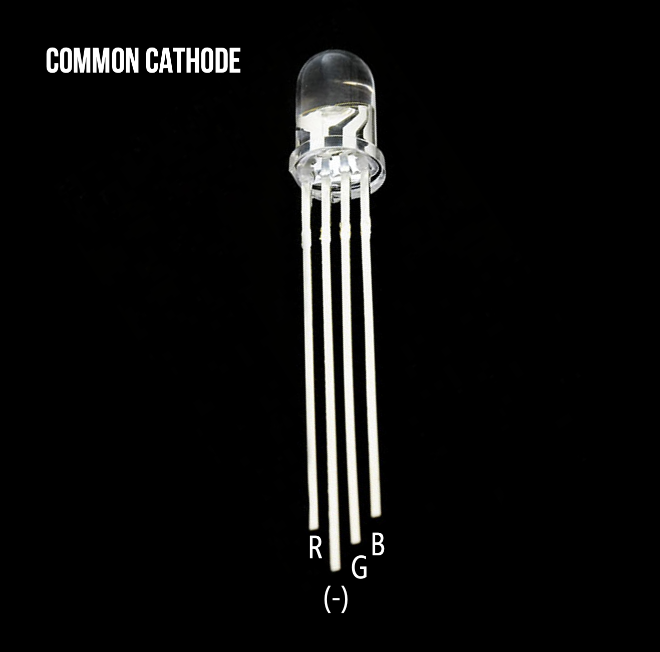 |
| A diffused Common Anode RGB LED from Adafruit. It’s called diffused because the epoxy casing is scratchy and not perfectly transparent | A clear Common Cathode RGB LED from Sparkfun. |
You cannot tell whether you have a Common Anode or Common Cathode RGB LED by visual inspection. Instead, consult the supplier website, the datasheet, or experiment with the LED yourself (remember, diodes only work in one direction so as long as you include your current limiting resistors, you should be fine!).
For this project I'm using a COMMON CATHODE RGB LED
For this section I decide to make a little presentation about microcontrollers that I can use for Fab Academy classes later:
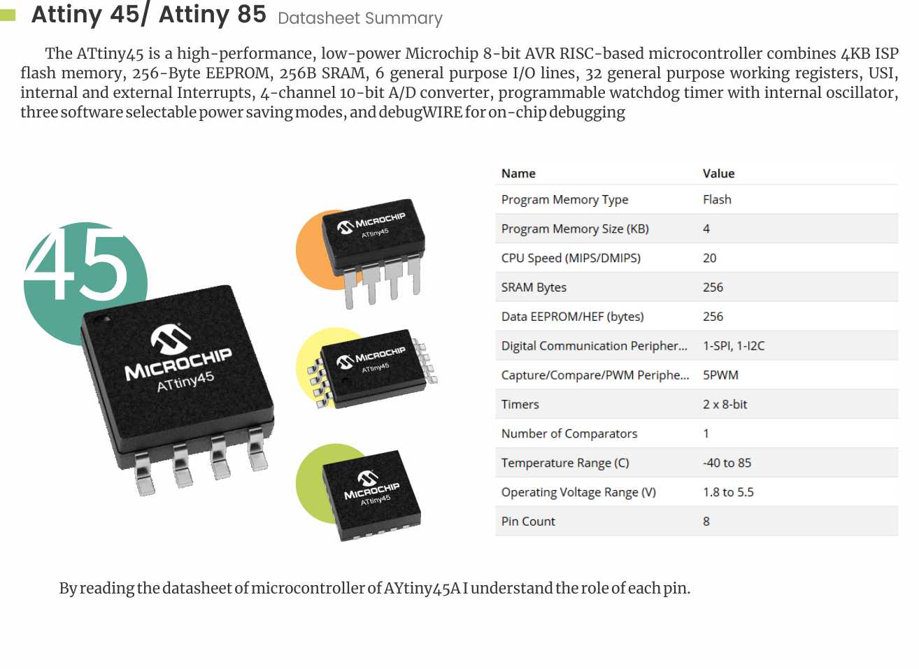
Microcontrollers: The Basics de Silvia LugoI decided to use the Attiny45, here's a recap of the useful information you can find in the datasheet of this chip and also info about the pinout
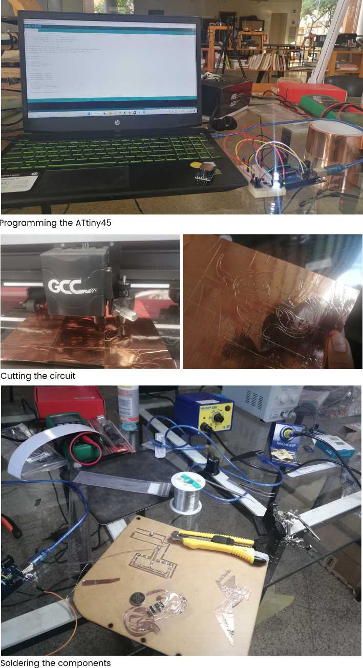
Here's a simple video that's really useful this week to make the arduino a programmer:
I'm going to be using and Arduino UNO, but any other arduino model should work


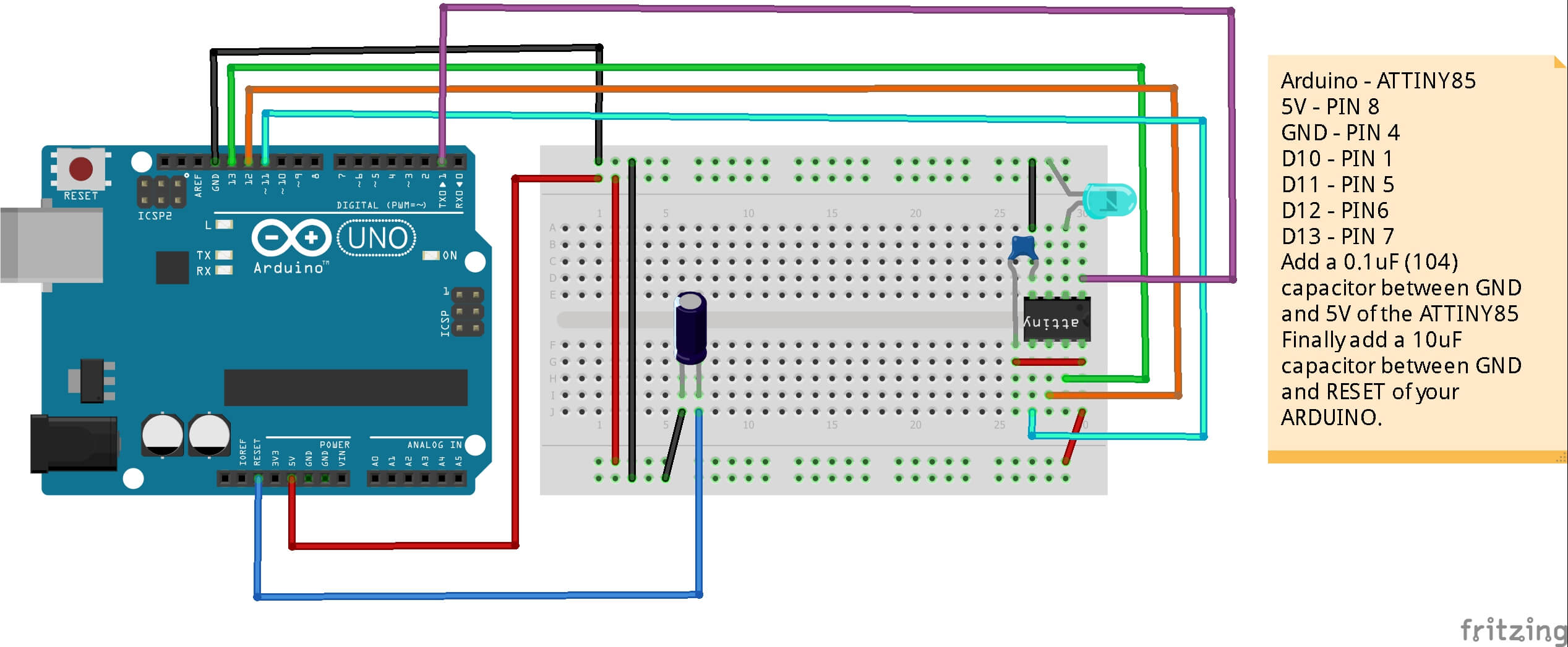
http://drazzy.com/package_drazzy.com_index.json
 We can remove the attiny and that's it. The chip is programmed.
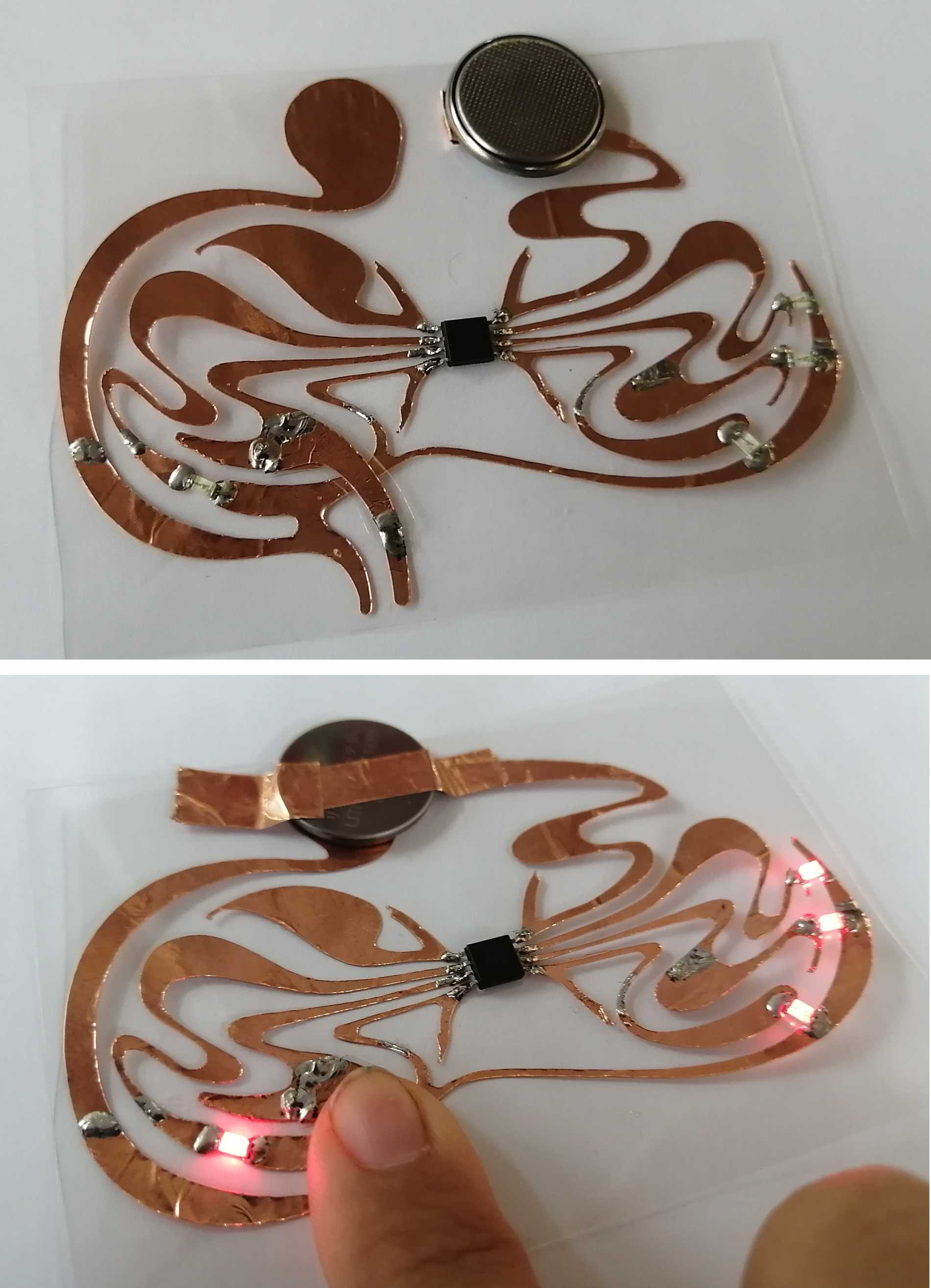
Now that I had my programmer I decide to built a simple circuit using a touch sensor as input and LEDs as an output.
According to Electronic Hubs the sense of touch is an important sensory channel in many animals and some plants. Our senses inform to us when our hands touch something. Computer input devices are indifferent to human contact as there is no reaction from software in the event of making, maintaining or breaking physical contact like touches or releases.
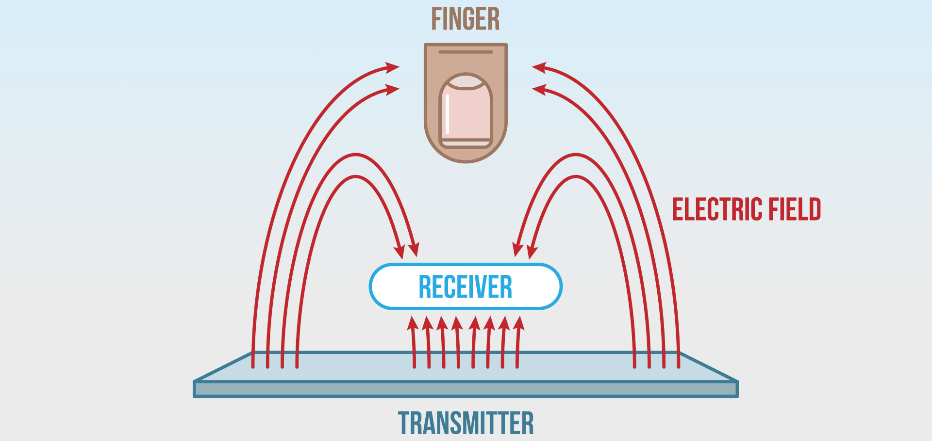
Thus, touch sensing input devices offers numerous possibilities for novel interaction techniques. Touch sensor technology is slowly replacing the mechanical objects like mouse and keyboard.
A touch sensor detects touch or near proximity without relying on physical contact. Touch sensors are making their way into many applications like mobile phones, remote controls, control panels, etc. Present day touch sensors can replace mechanical buttons and switches.
To build the circuit I use the code and the tutorial I found here: Microcontroller circuit with copper tape
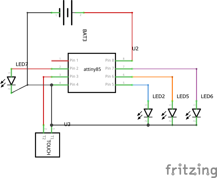
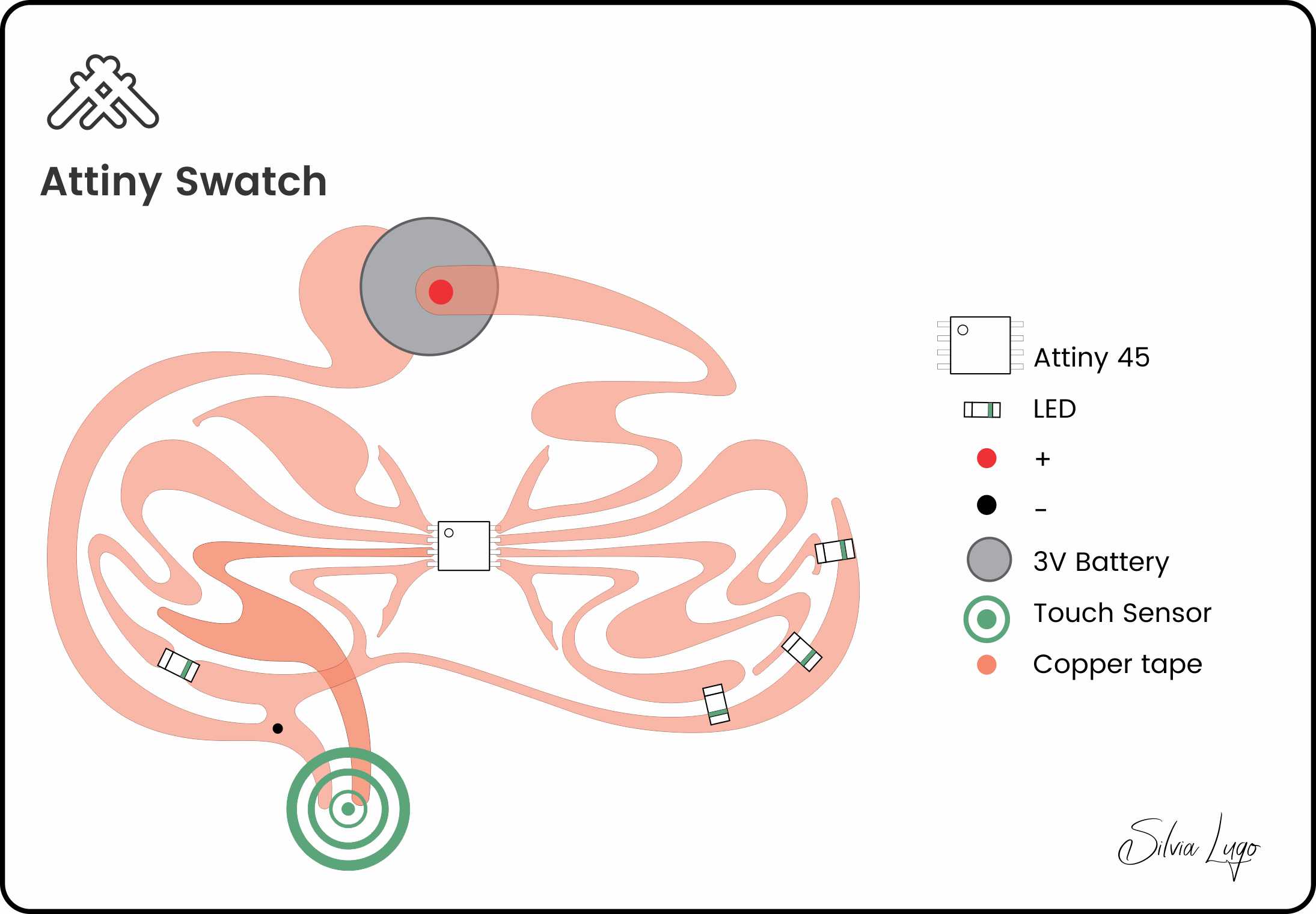
| Quantity | Part Type | Properties |
|---|---|---|
| 1 | 3V Lithium BatterY | CR 2450 |
| 4 | SMD LEDs | RED LED's SMD 0603 |
| 1 | attiny45 | Atmel AVR; version Attiny45-20PU |
| 1 | TOUCH pad | Resistive |
| 1 | Copper Tape | Paths |
| 1 | Fabric | Base |


Ultrasonic Sensor HC-SR04 and Arduino – Complete Guide
Lab: Tone Output Using An Arduino