05. E-Textiles
Week 05 | This week we got introduced into the world of electronics, wearables and microcontrollers! We used Arduino IDE to code the project and the Adafruit Flora as the microcontroller.
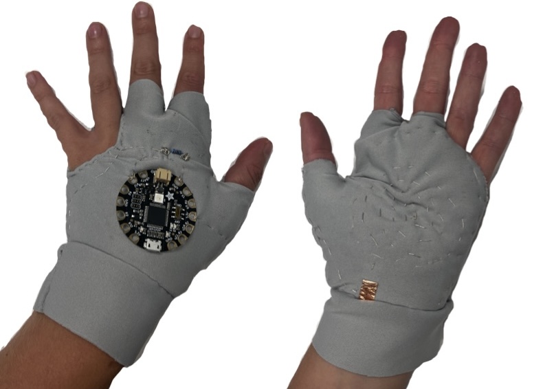
1Photo by Holly Adams - "Analog Glove with Adafruit Flora"
• • •
Introduction
Assignment
- Build at least one digital and one analogue soft sensor, using different materials and techniques.
- Document the sensor project as well as the readings got using the AnalogRead of Arduino
- Integrate the two soft sensors into one or two textile swatches using hard soft connections
- Document the circuit and its schematic
- Upload your arduino code as text
- Upload a small video of the swatches functioning
- Integrate the swatch into a project (extra credit)
I enjoyed combining my previous knwoledge of electronics with textiles this week which I haven't done before :). Exploring making a glove was fun, but using conductive thread and making pressure sensors were all new to me!
Inspiration
★࿐࿔Alumni: ★࿐࿔
- Anna Cain - similar idea to me of creating an LED necklace
★࿐࿔The Wider World!:★࿐࿔
Cyborg, artist and dancer - she has inserted sensors into her feet to feel the earths vibrations and translate this feeling into a dance.
One step beyond this week! I want to maybe grow crystals like these on either whatever I produce this week or on some biomaterials I create in biofabrication week.
I was thinking of creating an analog glove sensor so this process has helped me work through the steps
E-textile artist who has created a wearable haptic glove that controls musicians audio and visuals, and e-textile stretch circuits ( a "stretchy human breadboard"!?)
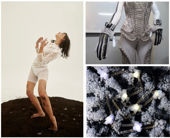
1Photo by Cyborg Arts on "Moon Ribas" | 2Photo by Rachel Freire on "Second Skin" | 3Photo by Instructables on "Growing Crystals on LEDs and ETextiles"
• • •
Tools
-
TinkerCAD - for drawing out circuit schematics and 3D diagrams
-
Fab Labs Docs - for info on setting up Arduino and Flora
-
Liza Stark, Soft Sensors - diagrams and video tutorials
• • •
Electronics Basics
Key Words
Voltage: The electrical potential difference between two points - measured in Volts (V)
Current: The rate of flow of charge - meausred in Amps (A)
Resistance: The opposition to the flow of electric current in a material or circuit - measured in Ohms (Ω)
Series Circuit : All components are connected end to end to form a single path in the circuit. Voltage is shared between each component, the current is the same in each component.
Parallel Circuit : An electrical path that branches so that the current is divided between each path. The voltage in each component is the same.
Short Circuit : A low resistance path for the current to follow. This results in excessive current flowing through the circuit.
Some basic electronics laws:
-
Voltage = Current x Resistance
-
Electricity runs from the positive terminal to the negative terminal.
-
Electrical energy follows the path of least resistance to the ground.
-
Resistance increases with distance, no matter the material.
-
Increasing the surface area for electricity to flow decreases the resistance.
-
If there's 0Ω in a circuit then there is infinite current which causes a short circuit
Building a circuit
This exercise was just a refresher for me and it actually felt fun doing it again since uni. We made a simple series circuit with a 9V battery, LED and 150kΩ resistor.
I used TinkerCAD to draw schematics and 2D models of the circuits.

Here is a simple parallel circuit hooked up to a power supply of 3.3V. I learnt that RGB LEDS all have different forward voltages depending on their colour - this means that they each shine with a different intensity. Warmer colours ( i.e. red) have a lower forward voltage so shine brighter than cooler coloured LEDS ( i.e. blue) which have a lower forward voltage. This meant that on our circuit each LED had a different brightness.

Designing a Digital Sensor Prototype
A digital sensor is one that only reads 0/1 or ON/OFF. I wanted to make one that was similar to a necklace clasp so that when the clasp was closed the circuit was running.
Liza Stark's image below describes the states of a button switch.
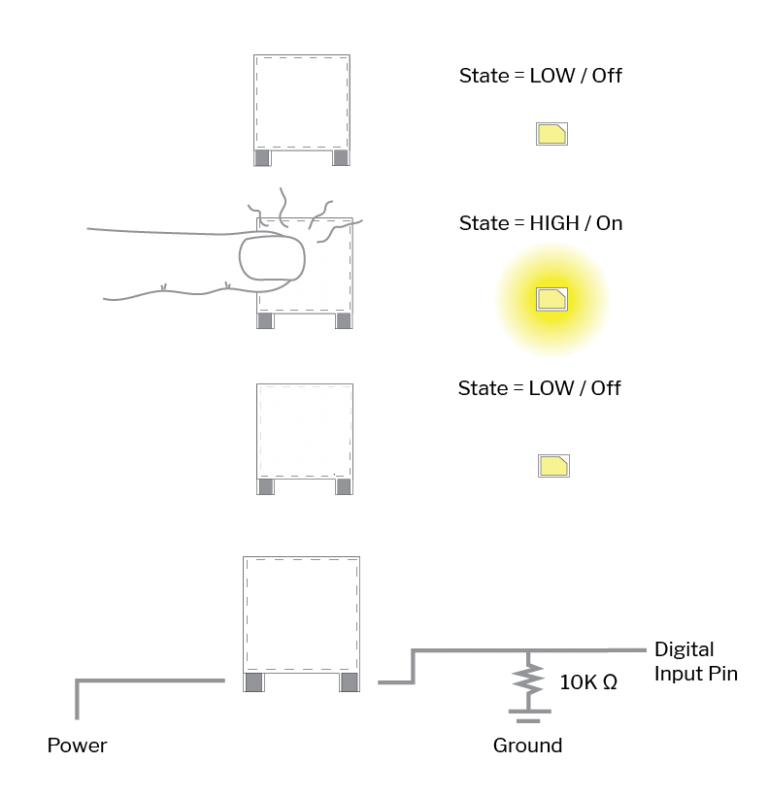
4 Photo by Liza Stark on "Soft Switches"
All you need is:
Equipment
- Yarn threads
- Conductive thread
- Conductive tape
- Normal tape
- Multimeter
I plaited some conductive thread through 2 pieces of yarn and taped the end with electrical tape, I taped the other end with normal tape just to keep the threads together.
With Citlali's help we tested the connections to check for continuity. The ends with normal tape were pressed to the multimeter (on the soundwave/continuity setting) while with our other hands we touched the two electrically taped ends together and heard a beeeeep so that's all good!

Designing an Analog Sensor Prototype
An analog sensor is one that has variable readings and for this we needed resistance - Velostat! I wanted to use the wool to create some sort of stress ball that can measure the pressure from your clench.
Liza Stark's image below describes the states of a soft pressure sensir using Velostat.
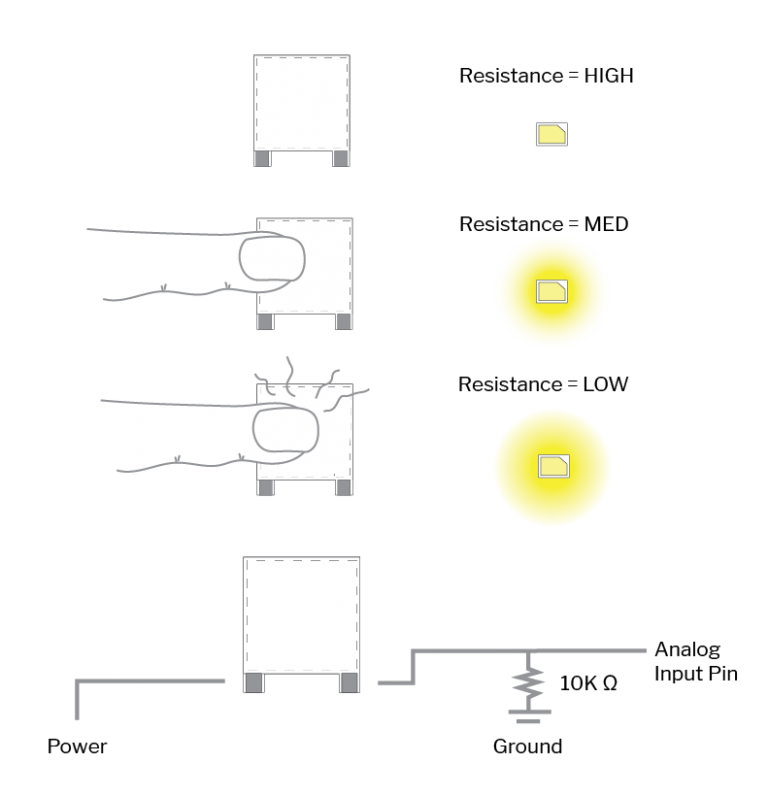
5 Photo by Liza Stark on "Soft Sensors"
All you need is:
Equipment
- Velostat
- Sewing needle and thread
- Conductive thread
- Conductive tape
- Multimeter
I cut some pieces of velostat and sewed them using normal thread to the centre of the wool. On the other side I scrunched up bits of wool and wound the conductive thread around them to make a tight ball which I placed behind the velostat - make sure that none is visible on the other side as if the two separate conductive thread pieces touch this creates a short circuit. Leave the ends of the yarn hanging out of the wool and tape them with electrical tape to make them easier to clip with alligator clips to the circuit.
Using the multimeter again we pressed the ends of the cables to the velostat and pressed down on the wool. The max resistance was ~20kΩ and the min was ~5kΩ - so I needed to choose a resistor for the next step at around the 10kΩ mark.

• • •
Adafruit Flora and Arduino
The Flora is a microcontroller board for wearable projects with many built-in features which you can upload to your designs through Arduino. You can check out the library of designs other people have made here :)
The important pins to note are:
- Ground
- Pin D12 (Digital) / A11 (Analog)
- Voltage 3.3V

Code Example
Here is the basic starter Arduino code to allow the Adafruit Flora to read the button sensor (Digital) and pressure sensor (Analog).
Remember:
- Analog sensor is connected to PIN 11
- Digital sensor is connected to PIN 12
int value;

// the setup function runs once when you press reset or power the board
void setup() {

  pinMode(11, INPUT); // Analog Pin 11/ Digital Pin 12 is connected to my sensor. Use INPUT for Analog sensor and INPUT_PULLUP for digital sensor so that flora uses the internal resistance of the microcontroller.

  Serial.begin(9600); // makes a communication between the computer and flora
}

// put your main code here, to run repeatedly:
void loop() {

  analogRead(11); // function to read our sensor which is connected to pin 11 for analog and pin 12 for digital. digitalRead() for digital sensor.

  value=analogRead(11); // value is going to continuously be reading whatever analogRead(11) is receiving.

  Serial.println(value); // prints the value
  delay(100); // gives a pause between each reading
}
• • •
Below are the values that the Flora records when the conductive ends are touched together on the Digital Necklace Clasp Sensor - notice how it is only 0/1 values.
Here are the values for when the Stress Ball Analog Pressure Sensor is pushed down. The values range from 0 - 400+.
• • •
Digital LED Necklace
I originally got excited when I saw some scrap electronics and thought that I wanted to make a necklace out of these waste chips - it ended up being a bit fiddly and not looking how I wanted but whatever here is the process..!
I chose to try and make a parallel circuit in the configuration below with LEDs and resistors. I simulated it on TinkerCad with all Red LEDs to see whether it would work or not first. I then began to assemble the ciruit with the equipment below.
Equipment
- Conductive thread
- 6 x LEDs of different colours
- 6 resistors ( Red : 220Ω, Other : 100Ω)
- 3 x scrap electronic chips
- Soldering iron
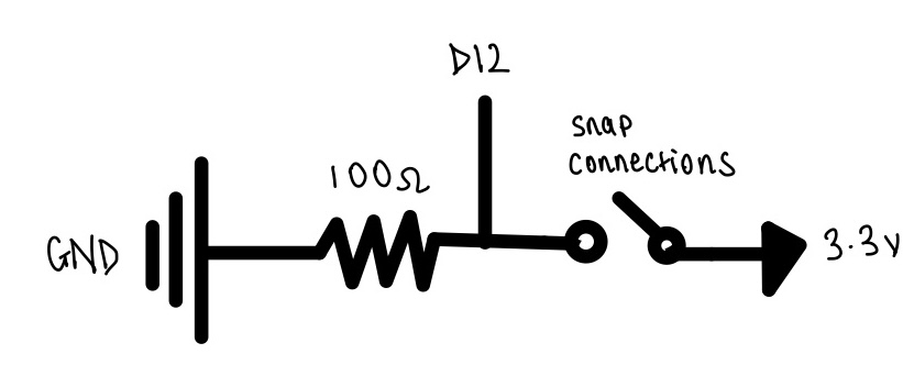
- Pair of snap connections
I had plaited the thread with normal yarn but only realised later I should have just plaited it all as conductive thread.
Following these steps helped me know whether or not my connections were secure.
- Thread the conductive yarn to the postive end of the resistor.
- Thread a new piece of conductive yarn to the negative side of the resitor and connect it to the positive side of the LED.
- Thread a piece of conductive yarn to the negative side of the LED.
- Connect the red cable of the power source to the positive end of the resistor and the black cable of the power source to the negative end of the LED - it should light up.
I then continued to make the first series row of 2 LEDs (Step 1 in the picture below). Then I made the second series row of 4 LEDs (Step 2) and connected the two rows in parallel checking each connection as I went (Step 3).

The next step was to add the snap connectors to the two ends of the 'necklace' to create the digital necklace. I used the soldering iron to help create more secure joints.
Remember
The button/switch i.e the snap connections need to be placed on the positive terminal of the battery, before the LEDs.

Review
What I found was that although each connection worked individually on the second series row, they didn't all light up as a row of 4 - only as a row of 3. I believe this may be due to the power of the battery and the circuit configuration as each LED is a different colour and has a different forward voltage. I decided to not do the last row of LEDs as I had planned as I suspected I would have the same problem.
Here is the updated schematic diagram after removing the last row of 3 LEDs and changing the LED colours. When I simulated this version it showed that all the LEDs would shine at different brightnesses as it did in real life. This schematic doesn't include the snap connection buttons because I couldn't find the right component on TinkerCad, it would be placed on the red wire of the battery before the LEDs.

Here is a simplified schematic ⋆。°✩
I also decided to scrap the whole idea of 'threading' each component together which made my life abit difficult and instead sewed the components to a bit of fabric which was sooo much easieer and less time consuming. I feel like I get caught up in an idea too quickly and then this happens!
• • •
Analog LED Glove
My plan for the Analog sensor was to create a pressure sensing glove using velostat, that when the hand was grabbed the Adafruit Flora's internal NeoPixel would change colour and brightness depending on the pressure values.
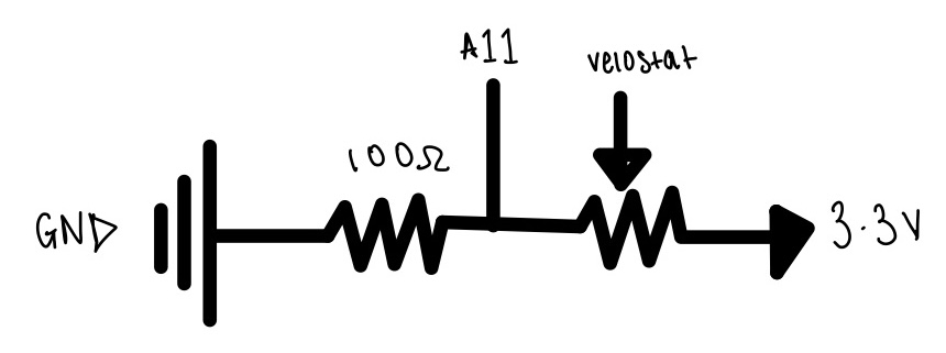
Here is the schematic ⋆。°✩
Below is an outline of what I wanted to create using the flora board.

Equipment
- Velostat
- Fabric for main glove section
- Fabric for boundary layer
- Conductive thread
- Conductive tape
- Adafruit Flora
- Normal thread
- 100Ω resistor
I followed these steps to design my glove!

- Simluate a prototype of the analog sensor with a breadboard, an LED and the Flora - shown in the videos below.
- Cut out the pieces of fabric - 2 x the shape of your hand (but leave alot of space for sewing), 1 x for inner layer, 1 x velostat, 1x boundary layer (red fabric).
- Add the conductive tape and sew the conductive thread onto the inner and bottom layer of grey fabric - make sure that the velostat covers the whole circle of thread. Make sure the tape and thread cross over!
- Sew the red boundary layer fabric onto the inner glove layer with normal thread, placing the velostat inbetween convering all of the conductive thread. Then sew the inner layer and outer layer of fabric together so that the velostat is ocovered.
✷
The next steps were assembling the top side of the glove:
- Place the adafruit in the centre of the top piece of fabric and sew the connections as seen in the outline of the process
- Sew the top and bottom pieces together to end up with below!
- Connect the Flora to the computer with the USB cable
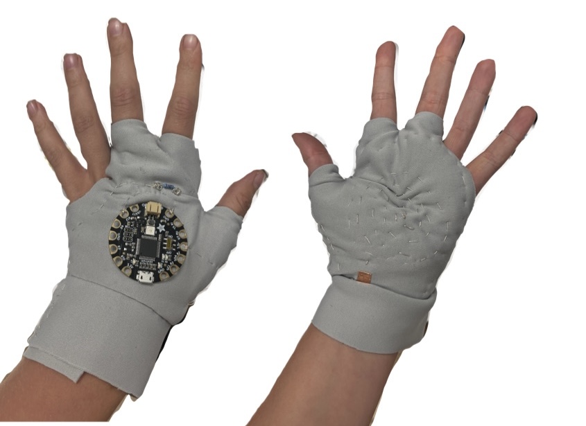
Here is the final product :)
• • •
Adafruit Flora Code
Below is the code to upload to the Adafruit Flora so that when the palm of the glove is pressed, the in-built NeoPixel changes colour and brightness depending on the pressure value.
Don't Forget!
- The sensor is connected to Analog Pin 11 (A11)
- Download the library 'Adafruit NeoPixel'
- The in-built NeoPixel on the Flora is assigned Pin 8
The code was formed through a combination of my previous knowledge on Arduino and ChatGPT's help.
#include <Adafruit_NeoPixel.h>

// Constants
#define PIN          8        // Pin for onboard NeoPixel on Flora
#define NUMPIXELS    1        // Number of NeoPixels (just 1 onboard)

// Pin for Velostat pressure sensor
#define SENSOR_PIN   A11       // Analog pin where the Velostat is connected

// Initialize NeoPixel strip object
Adafruit_NeoPixel pixels(NUMPIXELS, PIN, NEO_GRB + NEO_KHZ800);

// Variables
int sensorValue;              // Store the sensor reading (0-1023)
int brightness;               // Store the brightness value
int hue;                      // Store the hue value (0-65535)

// Function to convert HSV to RGB and set NeoPixel colour
void setPixelColorHSV(int hue, int brightness) {
  // NeoPixel uses hue values from 0-65535 (full color range)
  pixels.setPixelColor(0, pixels.ColorHSV(hue, 255, brightness));
  pixels.show();
}

void setup() {
  pixels.begin();             // Initialize the NeoPixel
  pixels.show();              // Initialize all pixels to 'off'
}

void loop() {
  // Read the pressure sensor (0-1023)
  sensorValue = analogRead(SENSOR_PIN);

  // Map the sensor value to a hue range (0-65535)
  hue = map(sensorValue, 0, 1023, 0, 65535);   // Full spectrum of colors

  // Map the sensor value to a brightness range (0-255)
  brightness = map(sensorValue, 0, 1023, 0, 255);

  // Set the NeoPixel colour using the HSV model
  setPixelColorHSV(hue, brightness);

  // Add a short delay
  delay(10);
}
Using pixels.ColorHSV(hue, 255, brightness) allows for a broader range of colours to be accessed on the NeoPixel by using the hue of each colour.
- As the pressure increases, the LED colour transitions from red -> orange -> yellow -> green -> cyan -> blue -> purple
- As the pressure increases the brighness goes from dim -> brighter
Review
Since it was my first time making a glove I think it went pretty good! I enjoyed making this more than the necklace probably because it worked better! I would like to see if I can grow crystals on this type of fabric...