5. E-textiles
Research
For research this week I found the work of previous student Alice Sowa to be super useful. She really helped me understand the process of building the circuit. It was clearly mapped out.
I wanted to keep this project super basic because I felt so overwhelemed after the lecture this week. I figured by starting by copying what other people have done I would get me over the initial intimidation and then more application ideas would flow. So I wasn't worried about creativity this time. The next e-textiles project I know I will have more ideas.
This was Alice's page:
- Knitted samples - Alice Sowa - Icelandic Textile Center
I also watched the class tutorials over many times.
Take Aways
These are some of my biggest beginner take aways. I felt they were important to note because for me they got lost in the shuffle of absorbing all the information at first but I figured them out later on my own. Next time I will keep them in mind at the start.
- Red cables represent power
- Black cables represent ground
- A bread board is used in the place of soldering. It's how you can test if your circuit before you solder. It just holds everything together.
- You should not have your sensor connected to the battery and the cable to your computer at the same time.
- On the AdaFruit Flora there is not a 5V pin. It is a 3.3V pin so I had to figure this out by googling when following the FabriXiao tutorial from class.
Tools
This is the AdaFruit FLORA pin out:

Process and workflow
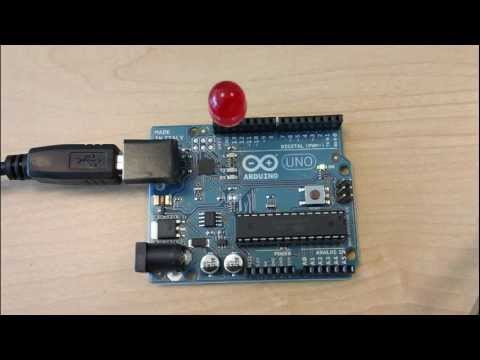
I started with the Arduino Uno to blink an external LED on a bread board just to get comfortable with the whole concept. I watched this tutorial called "Arduino: Lesson 1 - Blinking an LED" by techteachervideo
It was so perfectly simple and it worked. So it gave me a lot of confidence.
Click the image above to watch.
This is my light blinking on the bread board:

© Claire Cavanagh
Next I collected my materials and built the swatches, again by following Alice Sowa's work. I changed my design up a little bit but the schematic was basically the same.
To create a succesful digital switch we need a battery or power load. I created a channel made of wire and conductive thread. It attached to the __positive__terminal of the battery. My second channel was made of wire. It ran from the ground (or negative terminal) of the battery to the short leg of my diode. On a diode, the long leg is where you need to connect your positve channel so I had a separate piece of wire connected to this. When I wanted to turn my swtich on manually I pushed the positive wire into the conductive thread loop, completing the circuit. The loop held the wire in place until I was ready to turn the swatch of and pulled it out.
Here are the Switches and their Schematics:

This was my first digital swatch. I created it using wire and conductive thread. The conditive thread loops around the wire but it also acts as a stopper keeping the wire secure.
 © Claire Cavanagh

This was my second switch. I actually had to make it a second time, because as seen here, the first swatch had conductive stitches along the edges of the patch.
To unbug a problem in an electronic you need to know what factors might be causing the short.
- start by testing you battery with your voltometer to make sure it has enough
- next test you conductive wire or thread. I set my voltometer setting to beep when there is a current present. I pressed the volt reading cables along the wire at different points ( but mosty importantly the start and the end)
- next check if any of your wires are crossing. In my examples I discovered that, when folded over, these stiches in my sample were causing a short because the velostat wasn't fully separating them.
- I could see this when using the AdaFruit plugged into my computuer because my readings weren't consistent.

© Claire Cavanagh
It was now time to program the Adarfruit Flora V3. We didn't have the FabriXiao in our lab because there is a post strike so they didn't arrive in time. But I'm sure the process was similar and now I feel like I could easily switch to the Xiao.
When it came time to coding the switch it was good to understand from techteachervideo's tutorial above that the // symbol just means it was notes to help guide the process - not instructions for the board so this made it a lot easier to then read Nuria's instructions from our lecture. She had instructions in her notes on how to swap out the base code for the AdaFruit Flora so that was very helpful.
So first I did a blink test for the board to make sure it was working.
This was our AdaFruit Flora blink test code:
// Pin D7 has an LED connected on FLORA. // give it a name:
int led = 7;

// the setup routine runs once when you press reset:
void setup() {
  // initialize the digital pin as an output.


  pinMode(led, OUTPUT);
}

// the loop routine runs over and over again forever:


void loop() {
  digitalWrite(led, HIGH);   // turn the LED on (HIGH is the voltage level)
  delay(5000);               // wait for a second
  digitalWrite(led, LOW);    // turn the LED off by making the voltage LOW
  delay(1000);               // wait for a second
}
// Pin D7 has an LED connected on FLORA. // give it a name:
int led = 7;
// the setup routine runs once when you press reset:
void setup() {
// initialize the digital pin as an output.
pinMode(led, OUTPUT);
}
// the loop routine runs over and over again forever:
void loop() {
digitalWrite(led, HIGH); // turn the LED on (HIGH is the voltage level)
delay(5000); // wait for a second
digitalWrite(led, LOW); // turn the LED off by making the voltage LOW
delay(1000); // wait for a second
}
So this button was the cleaner second analogue switch with no stitching on the sides.
To create a succesful analogue switch we also start with a battery or power load.
My conductive material on this swatch was copper tape that I stuck to both sides of the square (triangle when folded). Between my tape I put a piece of velostat, a pressure sensitive polymer sheet. The velostat needed to completely cover the copper foil. My diode legs were down through the felt, through the velostat and came in contact with the copper foil so that it would turn on. But the beauty of the velostat is that it's resistance decreases the more it's pressed. So to manually work my switch I just had to slowly apply pressure to slowly see the diode turn on.
Here it is open and plugged in to the AdaFruit Flora:
 © Claire Cavanagh
And here it is close up to see all the copper tape and how it's connected to the gator clips:
 © Claire Cavanagh
The AdaFruit took a little trouble shooting because the numbers we were using as inputs weren't correct - so we asked chat GPT to identify what numbers on the board we should be inputting to the "const int"
We also used chat GPT to trouble shoot how to modify the code to say PRESSED and RELEASED instead of rising and falling numbers.
Because I ended up going with the internal resistor that existis in the AdaFruit I had to code it for a INPUT_PULLUP.
(It's imporant to understand that when you use an internal resistor on your board, the positive and negative (ground) channels are reversed. So if you wire your circuit as per usual, when you press your button, it will actually turn off. If you do nothing it will just stay on. So you need to either reverse your wiring or account for this in your code.)
So in my case we used a conditional if/else code.
If the sensor state was LOW the Serial Print would read PRESSED. Or Else if it was HIGH it would read RELEASED
Results
So here is the button showing the appropriate code depending on if it is being pressed or not.
Code Example
__So here was the final code
const int yellowPin = 6;     // Velostat connected to D6
const int ledPin = 7;       // Built-in LED on Flora
int sensorState = 0;

void setup() {
  pinMode(yellowPin, INPUT_PULLUP);  // Use Flora's internal pull-up
  pinMode(ledPin, OUTPUT);
  Serial.begin(9600);
  Serial.println("Flora Velostat Sensor (using internal pull-up) ready!");
}

void loop() {
  sensorState = digitalRead(yellowPin);  // Read HIGH or LOW

  if (sensorState == LOW) {
    digitalWrite(ledPin, HIGH);   // LED ON when pressed
    Serial.println("Velostat: PRESSED");
  } else {
    digitalWrite(ledPin, LOW);    // LED OFF when not pressed
    Serial.println("Velostat: RELEASED");
  }

  delay(200); // Short delay for stable readings
}
Reflections
Again, in summary I had a number of big lessons this week.
First to never cross your wires, as it will cause a short.
Also, every circuit board model has different pin numbers and you have to consult it's pinout sheet to know which ones to use.
It was also a good lesson to see how the Serial.printIN could be changed to read as PRESSED or RELEASED instead of a series of numbers. I was a good way to see how changes in the code affect the final reading.
Applications
I see this week's technoloy as being good for simple applications in perfomance. Perhaps it could be used to light up LEDs in a prop or costume on demand. I can also see it being useful for children's books that have an interactive element like a swtich the turns on a light.
It's a building block to go deeper into programing electronic pathways, reading their data on a circuit board and using that feedback to create even more dynamic outcomes.