8. Soft robotics
Research & Inspirations
Soft Robotic ~ Background
I have begun my documentation with an overview of soft robotics. Soft robotics is a specialized branch of robotics focused on designing robots from flexible, compliant materials such as silicone, gels, and fluids, rather than rigid components. Inspired by biological systems, these robots are developed for various applications, including medical devices, safe human-robot interaction, and space exploration, owing to their capacity to absorb impact and adapt to complex environments.
 SOFTROBOTICS IN OUTDOR APLICATIONS
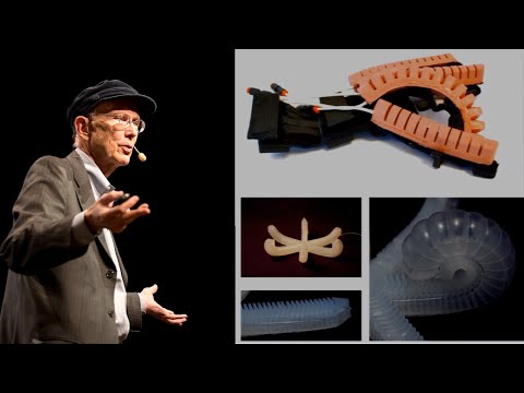
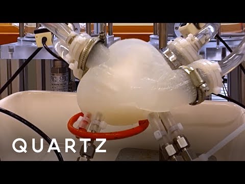
 Concept and structure of magnetic soft robotic chains for internal surgical applications (such as heart surgery).
### My Inspirations Soft robotics involves the study of devices designed to safely interact with people and their environment by utilizing flexible and malleable materials. This week, I drew inspiration from human organs such as the heart and lungs, which demonstrate natural soft actuation facilitated by chemical (ion-based) and fluid (air or blood) pressure mechanisms.


Reference of the pictures is the video below
My Soft Robotic Gripper With Exoskeleton
Steps
- 3D Design
- G-code (slicing the model)
- 3D printing
- molding and casting
- griper testing
list of materials tools , equipments needed
- 1 x M6 Air Hose Fitting (optional)
- 1 x Printed Mold
- 1 x silicone rubber (around 200 ml,)
- 1 x Knife/scalpel/scissors
- 1 x Old piece of cloth
- 3 x Printed Seperators
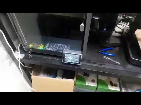
- 3d printer


These are the picture which shows the facilities used which include 3d printers and also chemicals usd which is slicon rubber.
MOLD DESIGN PROCESS
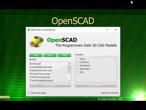
As mechanical engineer i like 3d modeling for each and every mechanical system. nomaly i use solidworks and matlab smulink but i get inspired with openscad software which can be installed in linux , which is also opensource .

 I installed openscad in my pc which was very easy, but since i was familia with solidworks , and blender openscads is a bit different becouse you have to use script then in order to obtain 3d model.
below you can find the video i followed to understand the basic of openscad
G-code (slicing the model)& 3D printing
After the model in OpenSCAD, exported it as an STL, and sliced it in Creality Slicer by setting layer height, infill, temperature, and supports. After generating the G-code, I transferred it to the printer via SD card and printed the model layer by layer.


- 3d printings the molds
Final mold after 3d printed

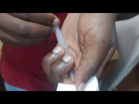
HANDMADE INFLATABLE with baking papers & thermal vinyl sheets
It was fun to create inflatables by hand, without the use of machines but only with scissors and paper. To do this you can use baking papers and you will also need two layers of vinyl sheet.
Below you will find a clear outline of how to follow this process

steps
- Think about your design, try to think of a shape that makes sense, make sure that the air has room to pass and that it does not get stuck between your shapes
- When you have a clear shape in mind you can draw it and cut it out in baking paper.
- Choose the color of your vinyl sheets and insert your shape between the two layers, make sure that a small rectangle of paper comes out of your sample, so that you can stick the straw
- Now you can centrally place your sample on a layer of baking paper on the heatpress machine base and on top of your sample.
- Press the Enter button and wait 10 seconds. The machine must be at 150 gr


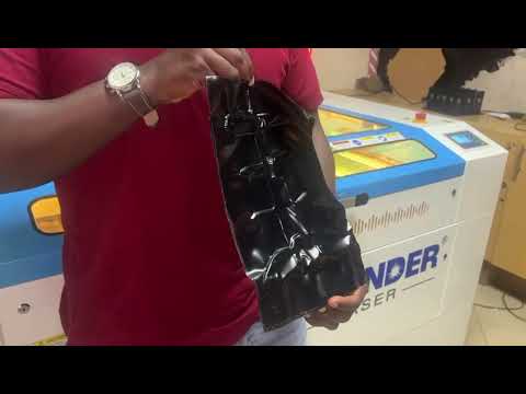
THE VIDEO SHOWS THE OUTPUT AFTER HEAT-PRESS
SECOND OF HAND MADE INFLATABLE with baking papers


VIDEO WHICH SHOWS THE SECOND TEST OF INFLATABLES
My hand drawn sketches are ... Lorem ipsum dolor sit amet, consectetur adipiscing elit, sed do eiusmod tempor incididunt ut labore et dolore magna aliqua. Ut enim ad minim veniam, quis nostrud exercitation ullamco laboris nisi ut aliquip ex ea commodo consequat. Duis aute irure dolor in reprehenderit in voluptate velit esse cillum dolore eu fugiat nulla pariatur. Excepteur sint occaecat cupidatat non proident, sunt in culpa qui officia deserunt mollit anim id est laborum.

Step
This model 1 was obtained by..
Lorem ipsum dolor sit amet, consectetur adipiscing elit, sed do eiusmod tempor incididunt ut labore et dolore magna aliqua. Ut enim ad minim veniam, quis nostrud exercitation ullamco laboris nisi ut aliquip ex ea commodo consequat. Duis aute irure dolor in reprehenderit in voluptate velit esse cillum dolore eu fugiat nulla pariatur. Excepteur sint occaecat cupidatat non proident, sunt in culpa qui officia deserunt mollit anim id est laborum."
Step
The laser cut nesting 2 was created using..
Lorem ipsum dolor sit amet, consectetur adipiscing elit, sed do eiusmod tempor incididunt ut labore et dolore magna aliqua. Ut enim ad minim veniam, quis nostrud exercitation ullamco laboris nisi ut aliquip ex ea commodo consequat. Duis aute irure dolor in reprehenderit in voluptate velit esse cillum dolore eu fugiat nulla pariatur. Excepteur sint occaecat cupidatat non proident, sunt in culpa qui officia deserunt mollit anim id est laborum.
Step
...
My hand drawn sketches are ...
This model 1 was obtained by..
The laser cut nesting 2 was created using..
footnote fabrication files
Fabrication files are a necessary element for evaluation. You can add the fabrication files at the bottom of the page and simply link them as a footnote. This was your work stays organised and files will be all together at the bottom of the page. Footnotes are created using [ ^ 1 ] (without spaces, and referenced as you see at the last chapter of this page) You can reference the fabrication files to multiple places on your page as you see for footnote nr. 2 also present in the Gallery.
3D Models
upload the 3d models of MakeHuman, Final 3d modelled body, 3D Scans, etc
This schematic [^4] was obtained by..
This tutorial [^5] was created using..
footnote fabrication files
Fabrication files are a necessary element for evaluation. You can add the fabrication files at the bottom of the page and simply link them as a footnote. This was your work stays organised and files will be all together at the bottom of the page. Footnotes are created using [ ^ 1 ] (without spaces, and referenced as you see at the last chapter of this page) You can reference the fabrication files to multiple places on your page as you see for footnote nr. 2 also present in the Gallery.
Code Example
Use the three backticks to separate code.
// the setup function runs once when you press reset or power the board
void setup() {
  // initialize digital pin LED_BUILTIN as an output.
  pinMode(LED_BUILTIN, OUTPUT);
}

// the loop function runs over and over again forever
void loop() {
  digitalWrite(LED_BUILTIN, HIGH);   // turn the LED on (HIGH is the voltage level)
  delay(1000);                       // wait for a second
  digitalWrite(LED_BUILTIN, LOW);    // turn the LED off by making the voltage LOW
  delay(1000);                       // wait for a second
}
Results
Video
From Vimeo
Sound Waves from George Gally (Radarboy) on Vimeo.