Soft robotics
What are Soft Robotics?
The "soft" aspect of soft robotics refers to the use of flexible materials instead of rigid ones in contrast to rigid-bodied robots built from metals, ceramics and hard plastics. The flexibility, deformability, and adaptability of Soft Robots allows them to squeeze into places rigid bodies cannot, which could prove useful in disaster relief scenarios as well as safer for human interaction.
Compared to traditional robots, in which rigid links are connected by joints, soft robots are composed of compliant materials and structures. Soft robots are continuum, configurable, and adaptable with functionalities relying on high degrees of freedom shape morphing.
Soft robotics combines biomimicry with technology to reproduce the structures, movements, and functional characteristics of living organisms. Drawing inspiration from plants, animals, and microorganisms, these principles can be applied in fields such as wearable technology, rehabilitation devices, prosthetics, and surgical robotics.
Although sensors are not part of the core definition of soft robotics, they can be incorporated to detect stimuli such as sound, touch, temperature, and human behavioural or emotional cues. These inputs allow the robotic system to respond appropriately to changes in its environment.
This week, we focused on understanding the principles of soft robotics. We began by creating a paper prototype to explore how inflatable structures work before developing a pattern for our own inflatable design using the materials provided by our Lab.
Nature Inspirations
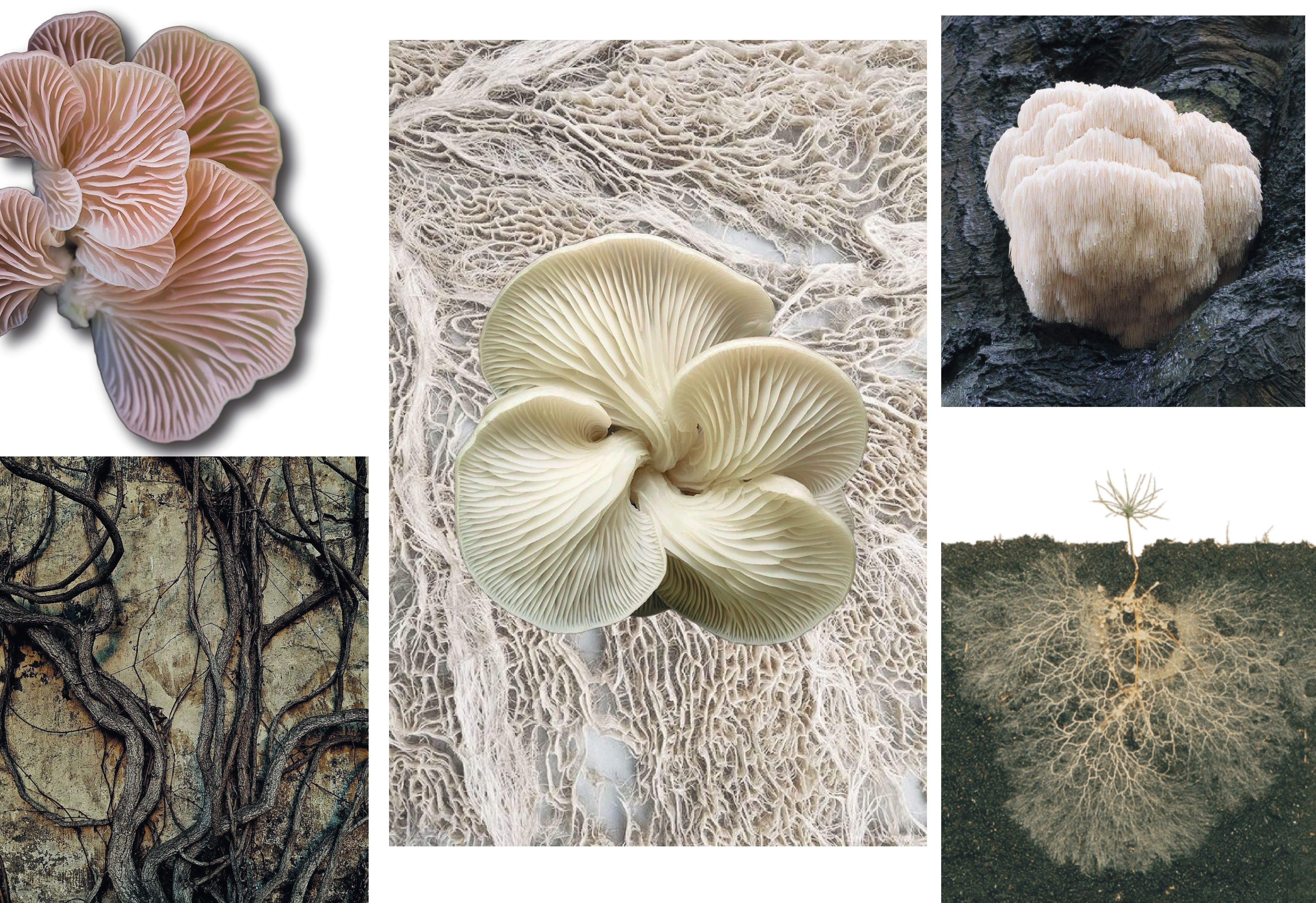
Moodboard with inspiration form growing Roots, fungos, etc - Images taken from Cosmos Website - Rita Manuelito/2026
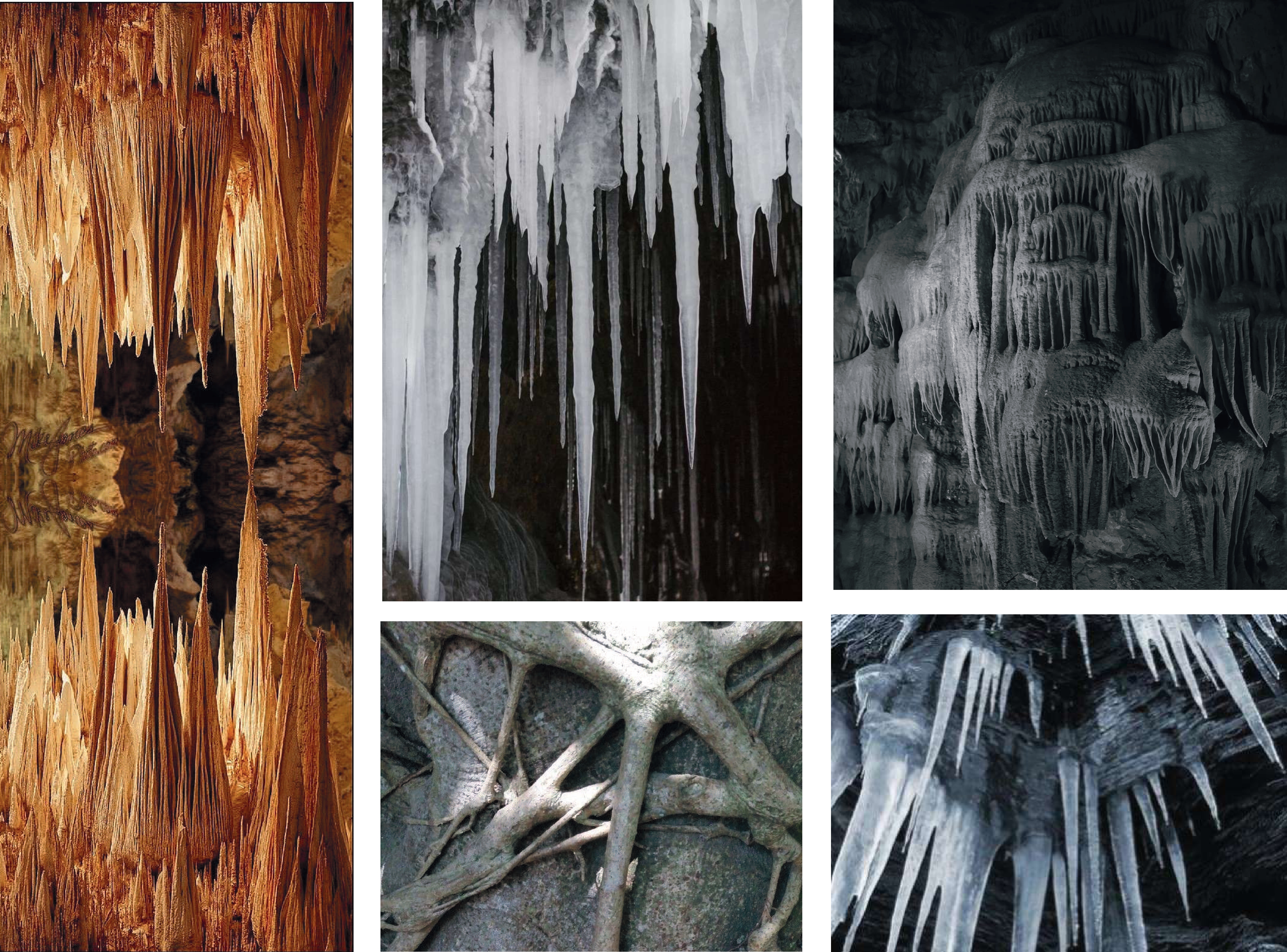
Moodboard with stalactite inspiration - Images taken from Cosmos Website - Rita Manuelito/2026
I wanted to explore this type of branching shape, so I used stalactite and stalagmite forms as a reference.
Sketches
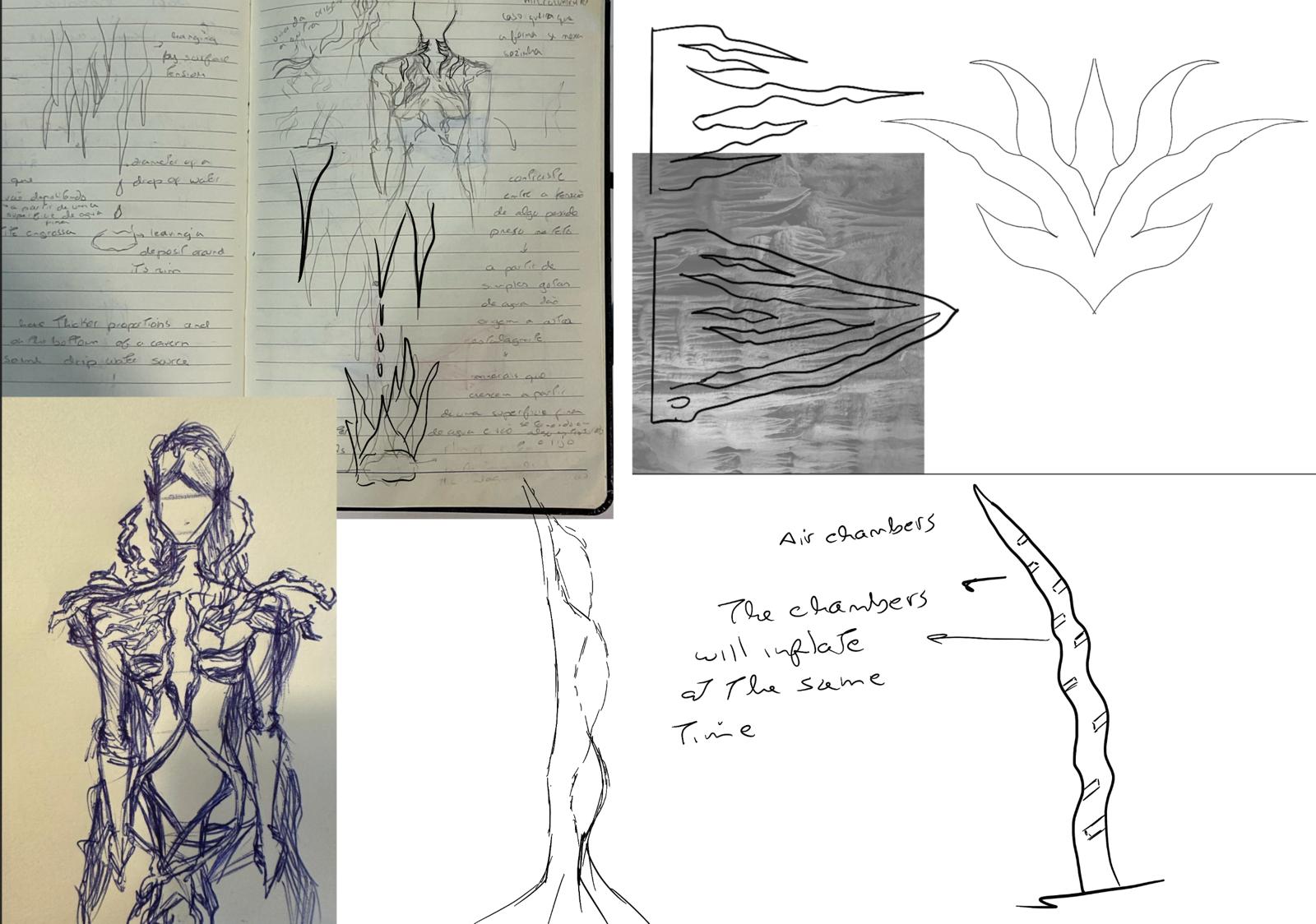
Sketches that I made to explore this shapes - Rita Manuelito/2026
For my own version on an inflatable i started by taking inpiration from several stalactites images and made some skectches of it's form and different variations while trying to keep some resemblance.
Applications
- Video references: Youtube (only when not yours)
Fashion - Wearable Technology
Agriculture & agritech
Soil monitoring, Precision Fertilisation and Land Rehabilitation
PLANTOID- The PLANTOID is a soft robot designed to explore soil in a similar way to plant roots. Instead of moving across a surface, it grows downward: each root tip contains an integrated 3D printer that extrudes its own tubular body as it advances, so the robot lengthens rather than travels. The tips carry soft sensors — touch, gravity, temperature, humidity and chemical — that measure soil pressure, detect obstacles and read the surrounding conditions, while a central unit in the trunk coordinates everything and communicates with an operator.
The Goal: To develop a robot that grows and adapts to its environment rather than moving through it, monitoring the soil in real time.
\rita-manuelito\docs\images\week08\softroboticgrowingroots.png
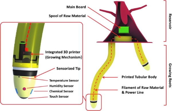
PLANTOID - Growing robot design
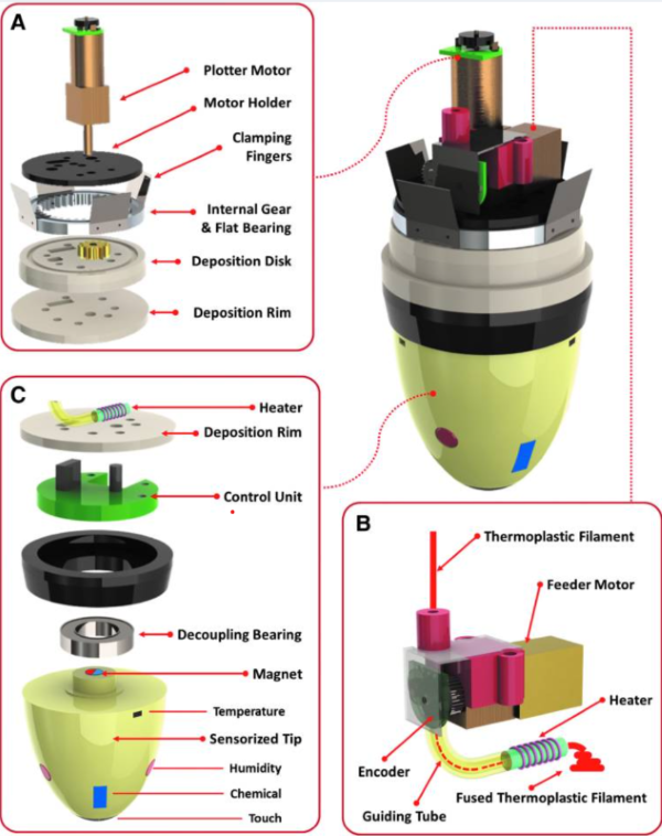
PLANTOID - Growing robot design
Original Artical of Study: Sadeghi, A., Mondini, A., Del Dottore, E., Mattoli, V., Beccai, L., Taccola, S., Lucarotti, C., Totaro, M., & Mazzolai, B. (2017). A plant-inspired robot with soft differential bending capabilities. Bioinspiration & Biomimetics, 12(1), 015001
https://iopscience.iop.org/article/10.1088/1748-3190/12/1/015001
How do Inflatables acctually work?
We began this module by creating paper prototypes to understand how inflatable structures work. For this purpose, I conducted two different experiments using the materials listed below:
Tools
᭪༊ parchment paper
᭪༊ thermoadesive vynil
᭪༊ scissors
1st Paper Prototype
For my first prototype, I began by drawing a simple flower design to observe how the shape would inflate. I cut the shape from parchment paper and then cut it twice from heat-activated adhesive vinyl, leaving a margin of approximately 2 cm. This allowed enough space for the two vinyl layers to be bonded together while leaving an opening through which air could enter.
After cutting the pieces, I placed the parchment paper shape between the two vinyl layers and ironed them together, with the shiny sides facing outwards.
Finally, we remove the protective plastic film from the vinyl.
୨ৎNOTE୨ৎ
The parchment paper mimics the chambers of a silicone mould, creating spaces through which the air can flow and expand.
It is important to create a parchment paper channel that extends beyond the edge of the vinyl. This provides an opening through which the air pump nozzle can be inserted to inflate the structure.
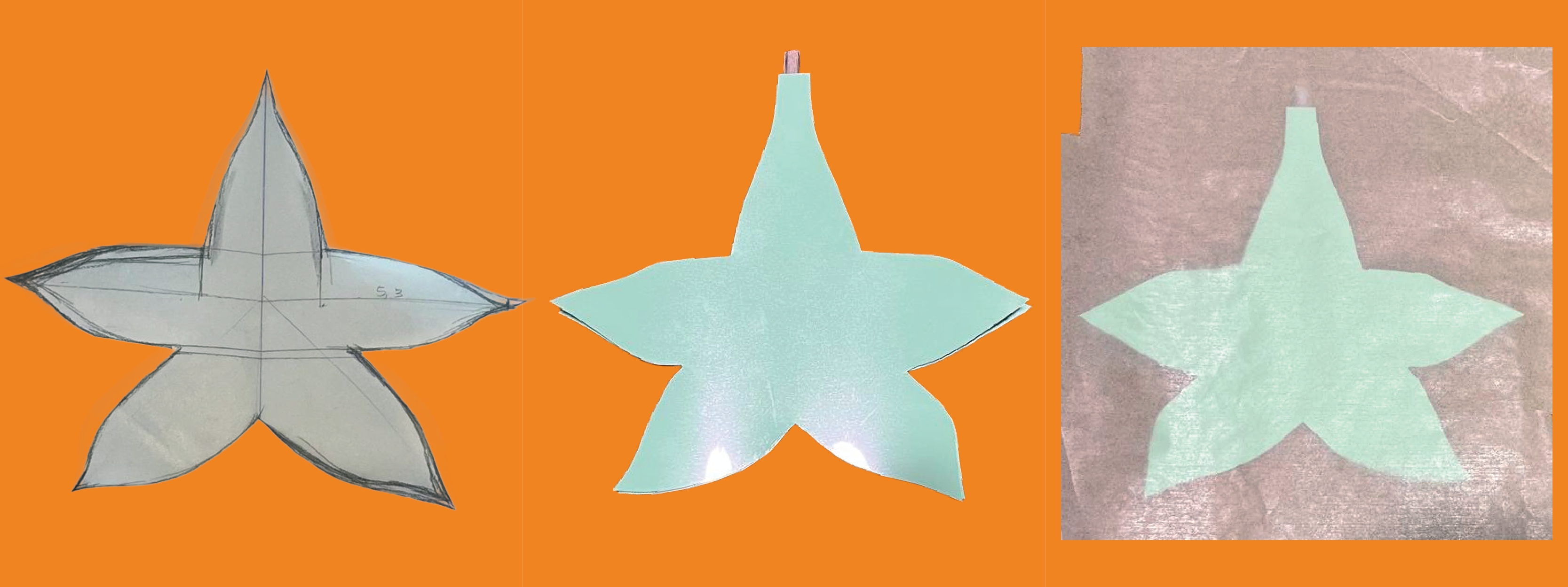
1st Paper Prototype - Inflatable - Rita Manuelito/2026
FOTOS VIDEO
2nd Paper Prototype
In the 2nd experiment I did the exact same, the only thing I did different was cutting losangle shape holes through out the petals to indicate where they would bend.
The heat-activated adhesive vinyl bonds in the areas where the parchment paper has been cut away. These sealed sections prevent air from entering, forcing it to flow around them and allowing us to control how the air moves through and expands within the pattern.
The size, shape, and placement of the parchment paper sections determine how the inflatable design bends and deforms. By changing these elements, we can create different movements and control the final shape of the inflated structure.
The sections of parchment paper that are cut away represent the spaces between the chambers of the 3D mould. The chambers incorporated into the design create the areas in which the structure inflates.
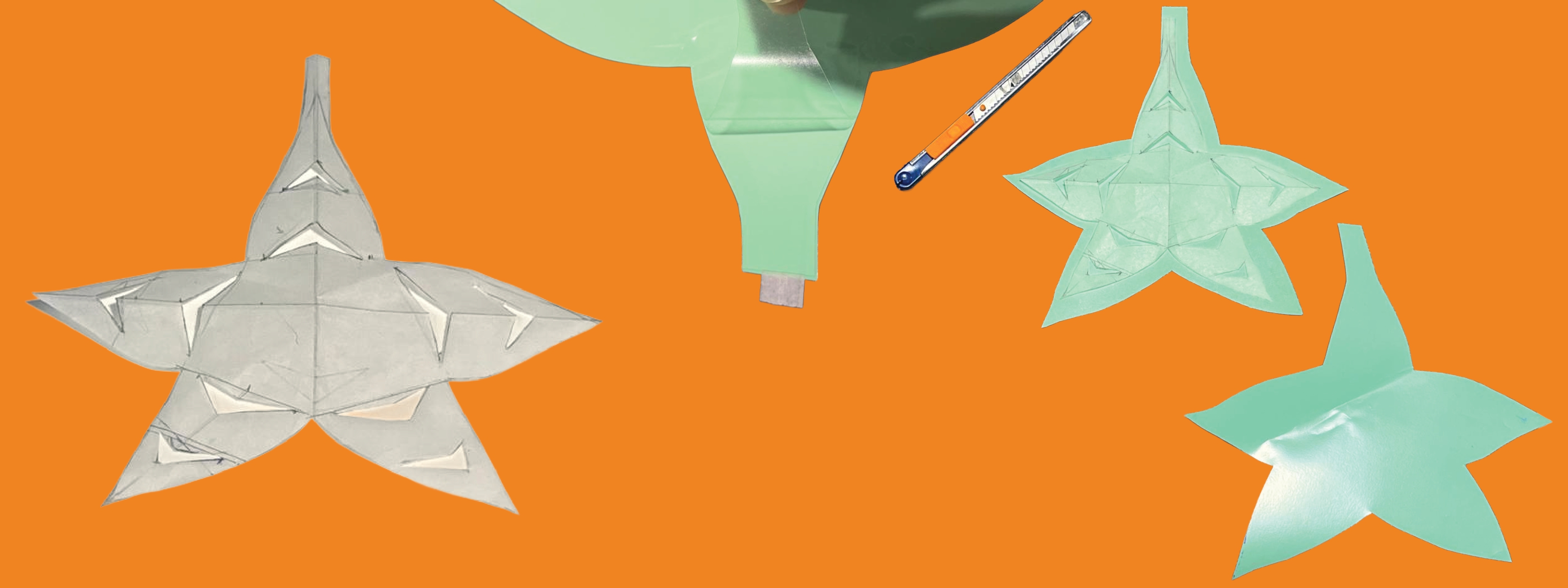
2nd Paper Prototype - Inflatable - Rita Manuelito/2026
My version of an inflatable - 3D Design
Sketches
For my own version on an inflatable i started by taking inpiration from several stalactites images and made some skectches of it's form and different variations while trying to keep some resemblance.
foto sketches
imagem chambers dentro de cada ramificação
Blender
FOTO
Edit Mode ▶ Add Cube ▶ Click A ▶ (Select All) ▶ Right Click ▶ Merge Edges ▶ At center
Select the vertex, press E to extrude it, and drag the mouse to draw the desired shape. Press E each time you want to extrude a new edge, then click to confirm its position.
After I drew about 2 branches I added a Skin Modifier so i could be able to see what i was creating.
Modifier ▶ Add Modifier ▶ Skin Modifier
୨ৎNOTE୨ৎ
᭪༊ To Join vertices, select the one you want to join and Click F
᭪༊ To resize vertices, select the vertex you want to resize and Click CTRL A
᭪༊ To resize with proportional editing, Click O and then Click CTRL A
᭪༊To Rotate a vertice or redefine its size, Click G
Then I proceded to added the Subdivision Surface Modifier ( make sure both levels for Viewport and Render were the same) and put this Modifier above the Skin Modifier
I continue to draw until I was satisfied with my model.
I then added another Subdivision Surface Modifier and played with the levels of Viewport and Render ▶ Added a smooth modifier and increased the factor to level ( I put 1,57) - you can repeat how many times you want but I left it like this.
After i was done reajusting my model by using the Short cuts I mentioened previously I exported the file in STL
PROCESSO
Fusion 360
My initial goal was to create several chambers within the model. However, I was unsure how to design a mould that could reproduce the complex 3D structure while also allowing the silicone to be poured effectively. With a rigid material, the mould could simply be broken to reveal the object inside. Since silicone is poured as a liquid, that would be impossible. So in order to create this chambers each branch would require a separate mould with individually designed internal chambers.
To increase the likelihood of success and make the experiment less time-consuming, I simplified the final model by isolating a single branch and creating a mould by dividing it in half with internal chambers. Although this process was still time-consuming, working with one branch allowed me to understand and test the mould-making process more clearly.
PROCESS
3D MOLD

Mold 3D - Rita Manuelito/2026
Sylicone Preparation
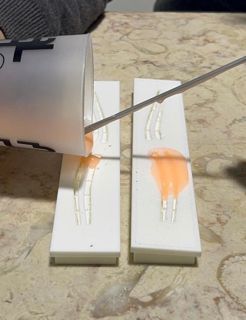
Mold 3D - Rita Manuelito/2026
Weigh out equal quantities of both silicone bases.
Base A — 16 g Base B — 16 g
Mix the two silicone components continuously for 3 minutes, ensuring that no air bubbles form.
Spread the mixture evenly into both moulds.
5. Results
Results & documentation
- Don’t forget to document the outcome including:
- Final result
- Photos from different stages
- Videos of movement or interaction, show how a material moves, something was assembled or the interaction
- Include measurements or a reference object to give a sense of scale
- Describe the (material) properties of what you made
- Comparison between attempts, if you did multiple experiments or generated multiple files before fabricating / deploying. You can use a table as shown in week 4
6. Weekly reflection & critical thinking
- What did I learn? What did I personally find interesting or surprised me?
- What would I do differently? If something "failed" do I know how else to tackle it now?"
- How does this connect to my final project or my learning trajectory?
- What are implications and possible applications, think also from the ethical or environmental aspect, how it could connect to your practice and project?
7. Fabrication files & References
References
Links:
https://zhaolab.stanford.edu/research/soft-robotics
https://www.sciencedirect.com/science/article/abs/pii/S2590238525000888
https://iopscience.iop.org/article/10.1088/1748-3190/12/1/015001
-
File: Laser cut matrix ↩
-
Reference: Author; Title; Source; year ↩