12. Skin Electronics#
This week I made a circuit involving conductive ‘lipstick’ and an LED. The more you press your lips together, the brighter the LED lights up.
Research#
Inspiration#
I totally was inspired by Katia Vega‘s interactive make-up projects. Moreover, I wanted to make a circuit that involved actuation by pressing one’s lips together. Since I wanted to explore electronic-skin interfacing, I researched make-up designs that would connect the mouth to other parts of the face. Lady Gaga’s make-up was a good start:

Circuit design and breadboard testing#
I followed the wiring as below

but followed the video below for guidance in adapting it for the LilyPad Arduino board since it was the first time I used the board.
My daughter helped validate that the circuit was working :)
Design concept#
Going with the thunderbolt make-up design and the circuit design in the aforementioned section, I drafted the following concepts of how components should be put together.


Materials research#
Graphite putty#
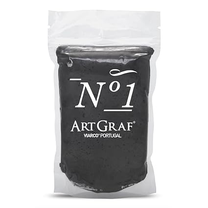
I had some graphite putty that I was experimenting from e-textiles week, which is actually a fun conductive material to work with. I read somewhere that this putty is the material that goes into pencils before it gets fired in a kiln to harden it. You can add water to it to change its consistency when drawing with it. It is water soluble and washes off with soap and water.

First trials and what didn’t work#
First, I made the mistake of individually gluing components onto my face. I laid down a peelable face mask, then put the components on my face one by one. The problem with doing it this way is that if you wait too long, the mask starts peeling off by itself. The second mistake I made was using Bare Conductive ink to connect all the components: it seemed to crack too much and the connection was not reliable.
Final product and lessons learned#
Below is a schematic of how the final product looks, with details on how I put everything together.

Useful information#
References and tutorials that helped#
Materials#
- LilyPad Arduino USB
- Adafruit Flex Perma-Proto - Half-sized Breadboard Flex-PCB
- Headphone wire
- Eyelash adhesive gel
- Graphite putty
- LiPo battery
- Lots of hair clips and bobby pins
Code uploaded to LilyPad#
The code was obtained from this instructable
int fsrAnalogPin = 2; // FSR is connected to analog 2
int LEDpin = 10;      // connect Red LED to pin 10 (PWM pin)
int fsrReading;      // the analog reading from the FSR resistor divider
int LEDbrightness;

void setup(void) {
  Serial.begin(9600);   // We'll send debugging information via the Serial monitor
  pinMode(LEDpin, OUTPUT);
}

void loop(void) {
  fsrReading = analogRead(fsrAnalogPin);
  Serial.print("Analog reading = ");
  Serial.println(fsrReading);

  // we'll need to change the range from the analog reading (0-1023) down to the range
  // used by analogWrite (0-255) with map!
  LEDbrightness = map(fsrReading, 0, 1023, 0, 255);
  // LED gets brighter the harder you press
  analogWrite(LEDpin, LEDbrightness);

  delay(100);
}


