I beggin my electronic journey during my fabacademy programme. I saw some; electronic production, electronic design, embedded programming, input signal, output signal and processing. Without these assignments, I would know nothing about electronic. It can be a good thing for me to go back to the basics, experiment with the soft electronic and do a revision to put me back into it.
Step 1 - The basic
- During the class, we did a very good review of a basic circut, Ohms'law, some basic components and tools.
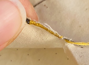
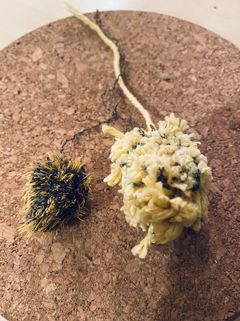
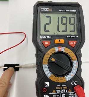
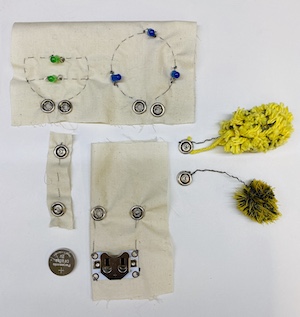
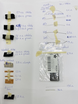
- I take all the conductive fabric that I can find in the lab for this week and play with it. Feel the fabric, the flexibility, the colors, the esthetics and most of all, the resistance of each so it can be compared. I was really suprise how our conductive embrodery wire was in reality not so conductive.
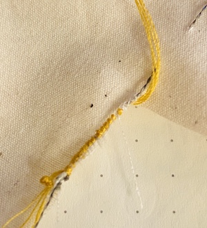
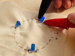
- Then I try to create some simple circut to experiment the jonction between the element. It was surprisingly easy, but I can imagine a lot of questions that can pop out when you do a real project with them. For exemple, I did a simple circut with 2 LED in parallele with a running stich and I figured that the wire is touching on both side so the isolation of the circut is something really important if you don't want any variation in your circut. I imagine some exemple of embedind circut and that lead me to just create a real project with it so all theses questions can be asked and find solution. Well... I am sure not all of them, but many of them.
- We have 2 types of sensors/connectors, digital and analog. The digital one is a ON or OFF status for exemple or a true or false or 0 or 1. It has a defined status. On the other hand, analog is the infinity between the status that it can give. For exemple it can read, 0 and 1, but also 0.4 and 0.99. If you want to do something that increases or decreases graduatly the electricity, you are in the analog device. If you are creating a switch, you are more in the digital device.
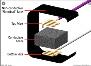
- Most of out material that I can make sensor with plays with the resistance in compression. We have different density of foam and velostat. I search on google some pressure sensor or capacitive touche sensor made with one of these material and lucky for me they have many. It have the Pressure pad on Arduino, a DIY smart insole and this O-mat project.
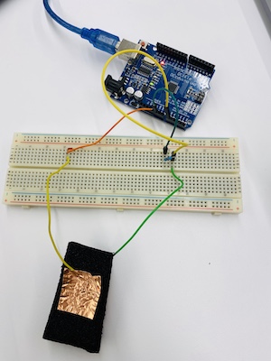
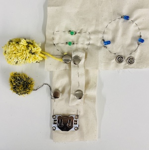
- I create different sensor with the foam, the velostat and copper tape and the soldering textile and link them to a breadboard with a led and a 3V battery. The LED make it to change the intensity but all of the foam, even with no pressure at all conduct a little bit and it's slow to take back it's shape. I think my final project will be around the shoe for all the weird feet that don't fit the standard. I think that this feet mat is something interesting to analyse how your weight is distributed on them.
- So let's go deep down with Force Sensor Resistance FSR. Here how to start.
Step 2- Create a project that includes softs sensor to pop out questions
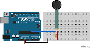
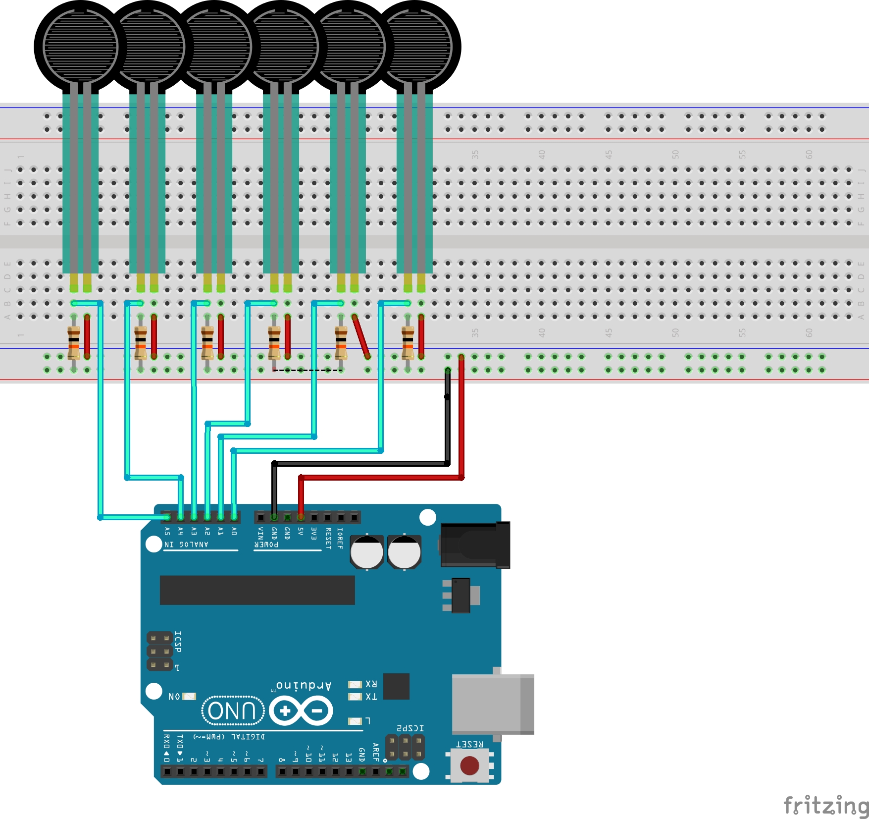
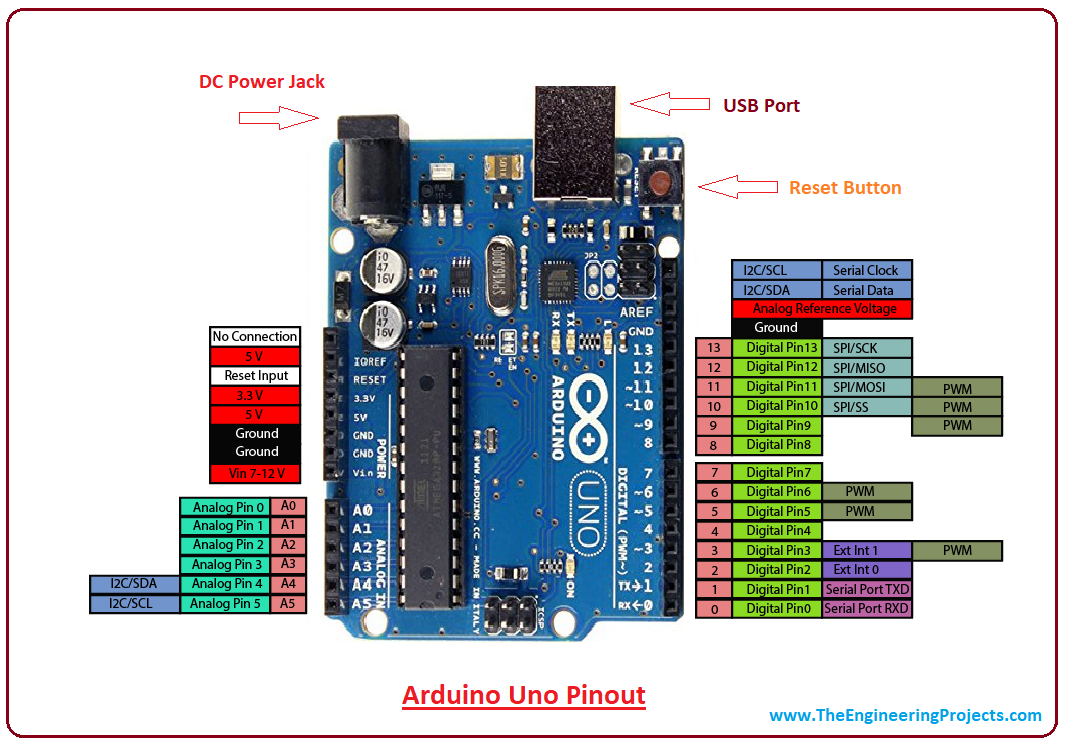
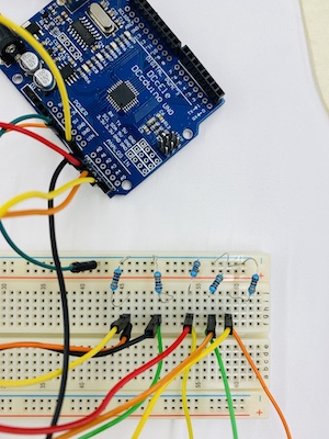
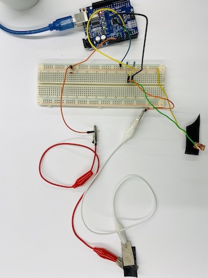
- For sure my sensor with foam works. You can see on these videos, the LED fade depending on the force I apply on the foam. I try to put an arduino and see what data it tells me for one sensor, the foam. I connect the vcc of the arduino to one side on the foam and the other leg I connected in parallel to A0 and a 10K resistor. This resistor is linked to the GND. This type of connection is the basic wiring for FSR sensor in arduino. Like I said before, the foam take really long time to go to his previous shape and so the data tell me too. It gives me some inconsistance. I try the same code with the velostat and it was much more precise and reactive. I put two sensors connected the same way.
- We need to be careful, each FSR pad (I have 9 in total) needs to be connected on a Analog pin like A0. All A pin can read an anolog signal, 0=0V and 1023=5V (Learn more on the analog vs digital read) For my project, I need 9 analog pins to read 9 differents variations of information.
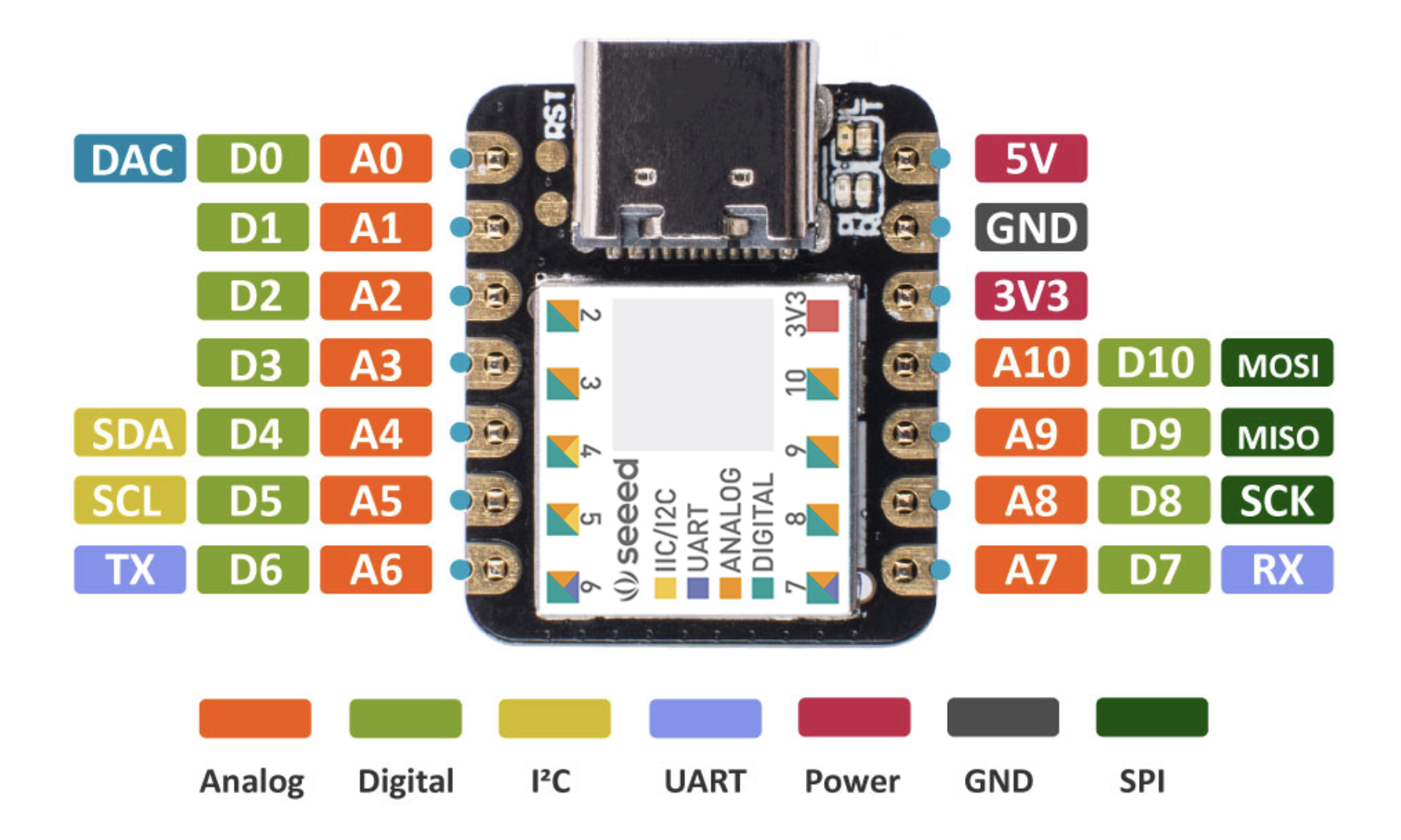
- I plan to use the seeduino for this project and like you see in the picture, the seeduino has 11 Analog pins.
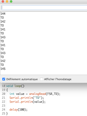
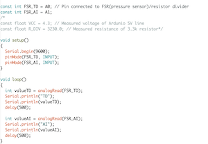
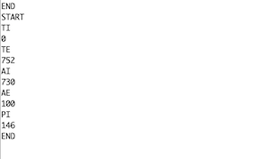
- First, I will test with the normal Arduino nano and only with the 6 analog pins. I struggle with the code, because I take the code of O-mat project, but they were transforming all the data into bytes so they can do a processing on top and that is not the goal for this week. Scrap everything and with a little bit of help of my collegue Francois. We just printed the raw data. For one sensor, it was fine. When I add the second one, I forgot to attribute a different name to my integer so my two appelations gave the same number. I changed that and TATAAAAA working!!! Nice the code works, I can pass to the object to figure how can I built multiple sensors in one without touching each other and be integrated in one object.
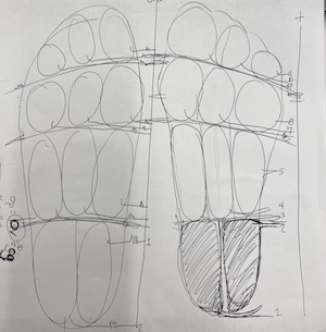
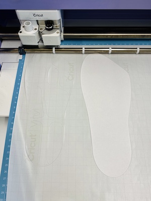
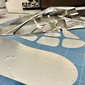
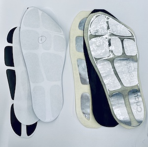
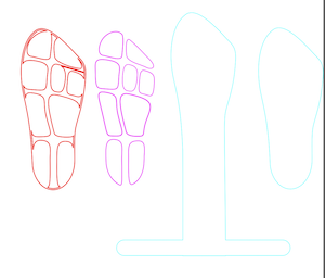
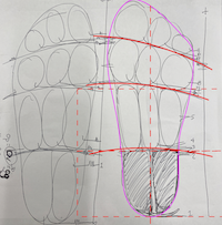
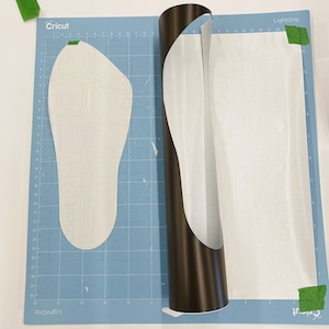
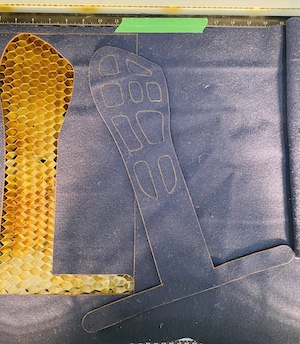
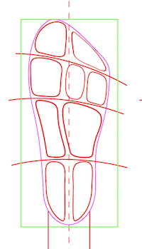
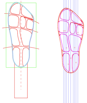
- I draw my foot on a paper and traced the outline and where it could be pertinent to have a sensor. Devided in 4 regions. I make some drawing on Inkscape and prototype with the vinyl cutter Cricut the layering of this big sensor. The big question is if we cut something conductive how can I transfer it and keep the exact position. I take the sticky mat and cut it up side down so when I take off the paper, I can laminate on something else.
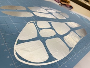
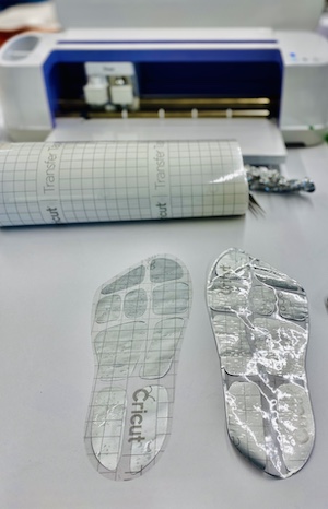
- I continue with the positive and negative conductive material that will touch to the velostat. Add laminated on transparent transfert paper. The esthetic is quite nice with the aluminium paper. Time to test!
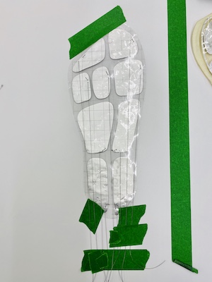
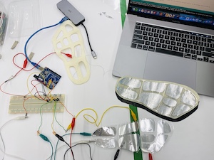
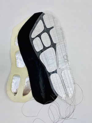
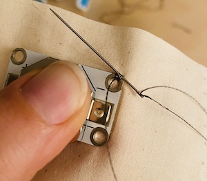
- With crocodile clips, I wire most of the negatives pads and test it with the code. Everything is fine again! I wire the aluminium foil with conductive wire and sandwich these same wire on top of it. I am pretty sure I can make better for this connection. Exemple here I use transfer paper, but it's the same process for fabric and vinyl for layered. Also, I can premake the hole on the top layer and soldered or tape the wire on top. Sewing a wire across aluminium foil creates large hole in the aluminium and weaken the connection.
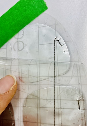
- I laser cut a spacer to go between the negative conductive part and the velostat and when I figure a way to integrate the arduino, I design the ankel part.
- I said arduino, but a arduino nano is quite big and difficult to integrate. I will go for a seeeduino. It's the same kind, but much smaller and sewable where the pin goes. A much better integration.
- Here is the productionfiles.