05 | E-TEXTILES
This week evoled around circuits, currents, analog- and digtal-switches, in otherwords E-textiles. We have touched upon the very basics of E-textiles, in order to understand the fundamental terms and aspects of combining electronics and textiles. I have touched upon it before, but during this course I got a proper understanding of the different elements of E-textiles. Our assignment for the week was making an analog- and a digital- textile switch, as well as getting introduced to Aurduino.
RESEARCH | IDEATION
In terms of E-textiles, I am most interested in the concept of another layer of interaction you can apply to the textile. I.e. using other interactions than the kinetic and the physical interaction with the textile, with the application of electronic sensors and programming you can alter the textile by heat, distant movement, speech etc. It becomes an interactive way of communicating with people. A very inspiring metaphysically-interactive work is the climate Change Series from 2019. The works visualize the change of climate measurements in real-time by coloured flip-discs that correspond to this change. The series is an attempt to create a connection between you and the afflicted areas, where our interactions have had a severe impact. Another more directly interactive work is the Pom Pom Mirror. Which through two-colored-textile components creates an interactive surface. These two works are based on more intricate mechanical engineering and sensors than we have access and knowledge to work with at the moment, so I also researched more basic switches that also touch upon visualising interaction. Works such as Ellinor F. Johansson who created interactive toys for children who deal with autism. She combines knit and electronics to create surfaces that are stimulating by touch. The interesting aspect of combining knit and electronics is that the electronics can easily be incorporated aesthetically in the surface, an aspect also shown in the Dangle Data Glove by Kobakant. Another aspect of interaction in the combination of textiles and electronics is the possibility to highlight movement, i.e. the kinetic movement to the body causes the textile to move, wich inturn causes a current that gives an electrically-caused change. This is simply shown by the Fish Scale Sensor by Kobakant.
Daniel Rozin, "PomPom Mirror," 2015 from bitforms gallery on Vimeo.
Expression Wall from Red Paper Heart on Vimeo.
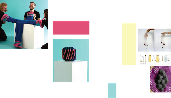
- 01 | CLIMATE CHANGE SERIES, 2019, BY BREAKFAST STUDIO
- 02 | POMPOM MIRROR, 2015, BYDANIEL ROZIN
- 03 | EXPRESSION WALL, 2018, BY Zander Brimijoin
- 04 | SENSORKNIT(TING), 2021, BY ELLINOR F. JOHANSSON
- 05 | DANGLE DATA GLOVE, NA, BY KOBAKANT
- 06 | FISH SCALE SENSOR, NA, BY KOBAKANT
- 07 | NOTIONAL FIELS, 2012, BY CUPPETELLI AND MENDOZA
PROCESS | WORKFLOW
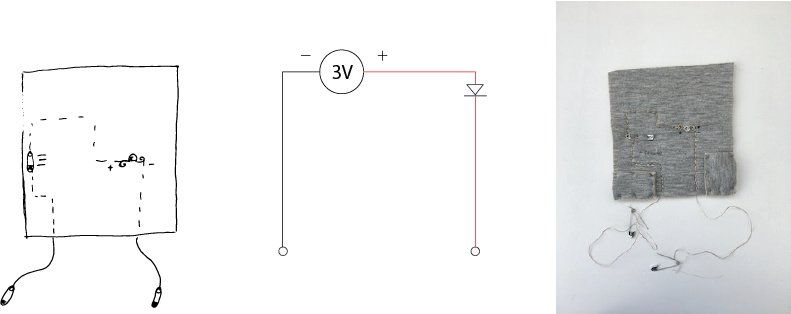
Much of this week has been based on understanding how to make textile sensors. The first thing we made was a Continuity Tester to be able to test our sensors. This tester consists of the following components:
- LED
- 3V battery
- Fabric
- Conductive thread
- Safety pins
- Sowing needle
- Siccors
GOOD TO KNOW | BASIC ELECTRONICS
An electrical current is created when electrons are passed from one atom to another, this is jumpstarted by a power source. It is described by the following quote from the famous chemist Antoine Laurent de Lavoisier "In nature, nothing is created, nothing is lost, everything changes". In this course, we are using the Arduino Uno microcontroller, which consists of a physical microcontroller board, i.e. a small computer on a single VLSI integrated circuit (IC) chip, with one or more processor cores, a memory, and input/output peripherals. The Arduino Uno also consists of a software, or IDE (Integrated Development Environment), where the code to control the micro controller can be written.
KEYWORDS:
- CIRCUIT | a path for electricity to flow through.
- VOLTAGE | Electrical pressure measured in Volt.
- CURRENT | Flow of electrons measured in Amps.
- RESISTANCE | The amount od material that resists the flow of current, measured in Ohms.
- OHM's LAW | V=IR
- TRACES | Pathways for the electricity to flow.
- Power source | Battery
- Short circuits| The electrons travells the shortest distance.
TOOLS
TUTORIALS
GOOD TO KNOW | DIGITAL SENSORS
The digital sensor is based on a binary system, where the current is either on or off, 1 or 0.1 Inspired to use knit as a medium to incorporate the electronics, I started to try to knit with the conductive thread we have available at the Fab-Lab. In a Brother Knitting Machine 950 it was easy to knit with the thread down to a stitch length of 4, and together with a wool thread, at a size 6. I decided to make a partial knit pattern, where the partial knit parts are hooked back up in the knit to create a wave pattern, these parts are made with one conductive thread and one wool thread, whereas the backing is of two wool threads. The idea is that when the array of waves touch it will create an electrical current.
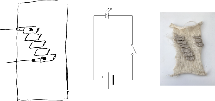
This sample worked semi-well, the waves need a lot of pressure if the electric current is applied in the waves further from each other. This is due to the amount of material the current has to pass through, creating too much restance, which was measured by the multimeter to be around 0,6-0,3. I should probably not have mixed the threads, to lower the resistance, as is shown by the multimeter, but the hand of the combined knit was far nicer than the pure one, which is an important factor it is to be interacted with. What is interesting is that the electric current can be applied to any of the waves, which gives you an idea of how the amount of material and thereby resistance is important for how well the current flows.
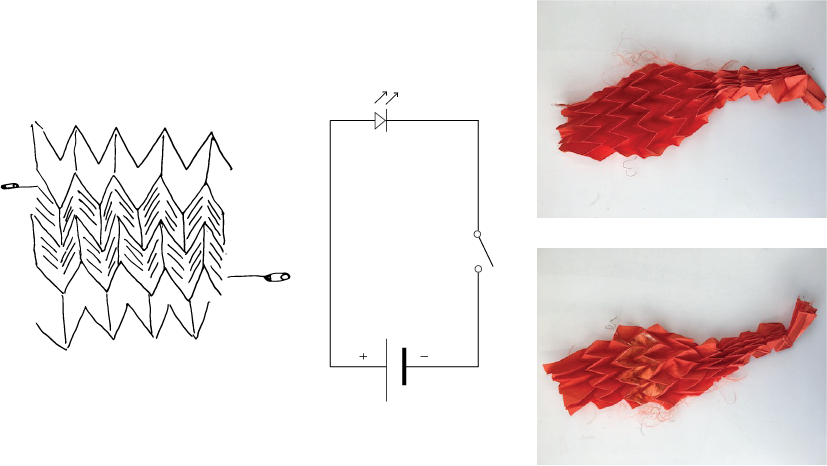
I also made a second digital sensor exploring the movement of folding, using conductive tape to create the circuit. The folds were created by making two paper folds, placing the polyester fabric in between them, and then heat-press it at 150 degrees for 30 sec twice, turning the pleated fabric over. The folds in the fabric get more rigid by the application of the tape which gave it a nice rigidity to it.
Code
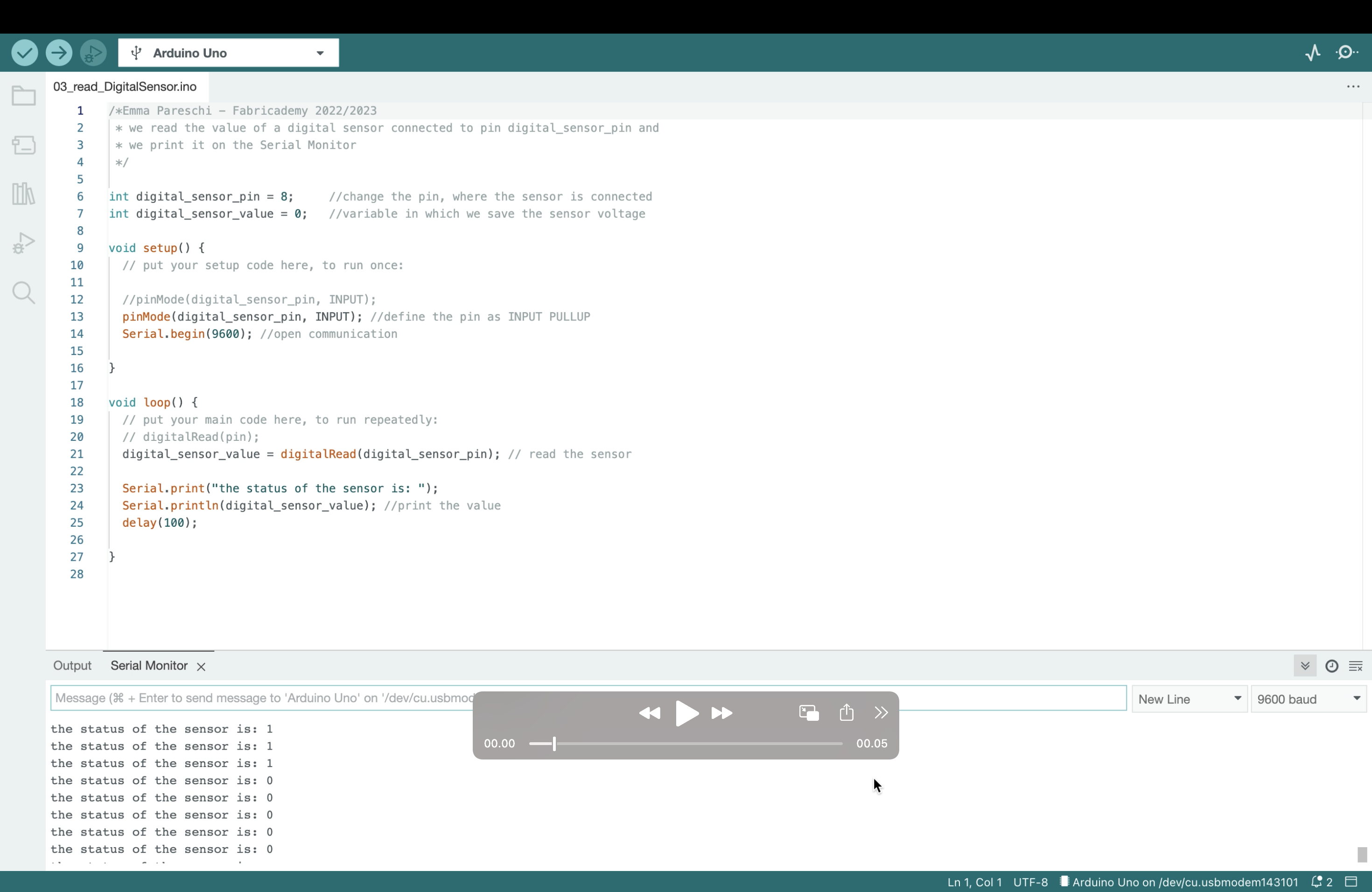
DIGITAL SENSOR WITH SERIAL MONITOR
/*Emma Pareschi - Fabricademy 2022/2023
 * we read the value of a digital sensor connected to pin digital_sensor_pin and
 * we print it on the Serial Monitor
 */
int digital_sensor_pin = 8;     //change the pin, where the sensor is connected
int digital_sensor_value = 0;   //variable in which we save the sensor voltage

void setup() {
  // put your setup code here, to run once:

  //pinMode(digital_sensor_pin, INPUT);
  pinMode(digital_sensor_pin, INPUT); //define the pin as INPUT PULLUP
  Serial.begin(9600); //open communication

}

void loop() {
  // put your main code here, to run repeatedly:
  // digitalRead(pin);
  digital_sensor_value = digitalRead(digital_sensor_pin); // read the sensor

  Serial.print("the status of the sensor is: ");
  Serial.println(digital_sensor_value); //print the value
  delay(100);

}
GOOD TO KNOW | ANALOG SENSORS
An analog sensor is a range value, meaning that it there is a range between the on and off2: For the analog switch, I was thinking of physical and bodily interaction and decided to make an interactive nipple, using crocheting as the medium. I based my pattern on a couple of tutorials on how to make knitted knockers for people who cannot get a breast replacement. This made me fantasize about knitted prosthetic breasts that can transfer the sense of touch. What if we could remake the sense of touch to the people who have lost their breasts?
This simple analog sensor is made by crocheting with two coloured wool yarns to create a breast-like shape. Thereafter a pressure switch is made by using velostat, conductive thread, and insulation tape. By making the pressure switch separately it allows for testing it out before attaching it to the textile. The pressure works best when one conductive yarn is taped to the velostat directly above the other, making their connection possible when pressure is applied. The best way of ensuring the connection is spiraling the end of the yarn, increasing the area of connection. When the pressure pad works the two ends of the conductive yarn are sewn into the crochet so the pressure pad is placed in the middle, so it is tucked under the nipple. Thereafter each yarn can be connected to the circuit.
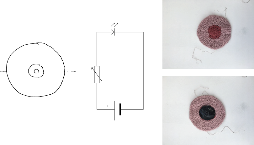
This sensor worked well, but the pressure needed is a lot more than I would have exprected.
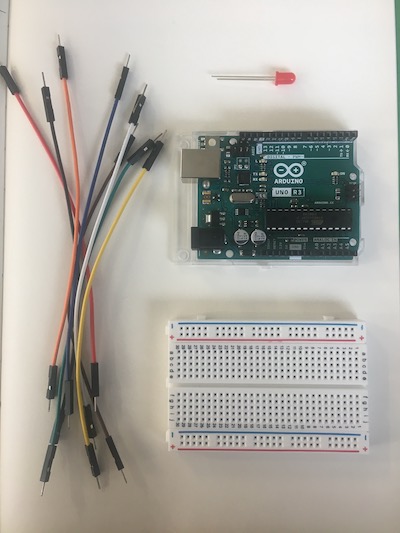
GOOD TO KNOW | ARDUINO
This was a tutorial in how to work with the sensors and Arduino, so here we followed Emma Pareschi's wonderful tutorial and workshop to connect our own sensors to the Arduino board and the Bread board.
DIGITAL SWITCH | LED BLINK

/*Emma Pareschi - Fabricademy 2022/2023
 * I turn on a led and I turn it off
 * The Led is connected to pin 3
 */
int led_pin = 3 ; //defin the pin where the Led is connected

void setup() {

  pinMode(led_pin, OUTPUT); //define pin of the Led as an output

}

void loop() {

  digitalWrite(led_pin, HIGH); //turn the Led on
  delay(1000);                 //wait 1000millisecond
  digitalWrite(led_pin, LOW);  //turn the Led off
  delay(1000);                 //wait 1000millisecond

}

ALTERED | DIGITAL SWITCH | LED BLINK

int led_pin = 3 ; //defin the pin where the Led is connected

void setup() {

  pinMode(led_pin, OUTPUT); //define pin of the Led as an output

}

void loop() {

  digitalWrite(led_pin, LOW); //turn the Led on
  delay(2000);                 //wait 2000millisecond
  digitalWrite(led_pin, HIGH);  //turn the Led off
  delay(2000);                 //wait 2000millisecond

}
DIGITAL SENSOR WITH SERIAL MONITOR
/*Emma Pareschi - Fabricademy 2022/2023
 * we read the value of a digital sensor connected to pin digital_sensor_pin and
 * we print it on the Serial Monitor
 */
int digital_sensor_pin = 8;     //change the pin, where the sensor is connected
int digital_sensor_value = 0;   //variable in which we save the sensor voltage

void setup() {
  // put your setup code here, to run once:

  //pinMode(digital_sensor_pin, INPUT);
  pinMode(digital_sensor_pin, INPUT); //define the pin as INPUT PULLUP
  Serial.begin(9600); //open communication

}

void loop() {
  // put your main code here, to run repeatedly:
  // digitalRead(pin);
  digital_sensor_value = digitalRead(digital_sensor_pin); // read the sensor

  Serial.print("the status of the sensor is: ");
  Serial.println(digital_sensor_value); //print the value
  delay(100);

}
ANALOG SENSOR | LED FADE
/*
  Smoothing

  Reads repeatedly from an analog input, calculating a running average and
  printing it to the computer. Keeps ten readings in an array and continually
  averages them.

  The circuit:
  - analog sensor (potentiometer will do) attached to analog input 0

  created 22 Apr 2007
  by David A. Mellis  <dam@mellis.org>
  modified 9 Apr 2012
  by Tom Igoe

  This example code is in the public domain.

  https://www.arduino.cc/en/Tutorial/BuiltInExamples/Smoothing
*/

// Define the number of samples to keep track of. The higher the number, the
// more the readings will be smoothed, but the slower the output will respond to
// the input. Using a constant rather than a normal variable lets us use this
// value to determine the size of the readings array.
const int numReadings = 10;

int readings[numReadings];      // the readings from the analog input
int readIndex = 0;              // the index of the current reading
int total = 0;                  // the running total
int average = 0;                // the average

int inputPin = A0;
int led_pin = 3; //change the pin of the Led

void setup() {
  // initialize serial communication with computer:
  Serial.begin(9600);
  // initialize all the readings to 0:
  for (int thisReading = 0; thisReading < numReadings; thisReading++) {
    readings[thisReading] = 0;
  }

    pinMode(led_pin, OUTPUT);   //initialize led pin
}

void loop() {
  // subtract the last reading:
  total = total - readings[readIndex];
  // read from the sensor:
  readings[readIndex] = analogRead(inputPin);
  // add the reading to the total:
  total = total + readings[readIndex];
  // advance to the next position in the array:
  readIndex = readIndex + 1;

  // if we're at the end of the array...
  if (readIndex >= numReadings) {
    // ...wrap around to the beginning:
    readIndex = 0;
  }

  // calculate the average:
  average = total / numReadings;


  // send it to the computer as ASCII digits
  Serial.println(average);
  average = map(average, 60, 230, 0, 255); //we change the range
  average = constrain(average, 0, 255); //we apply the limits

  delay(50);        // delay in between reads for stability
  analogWrite(led_pin, average);
}
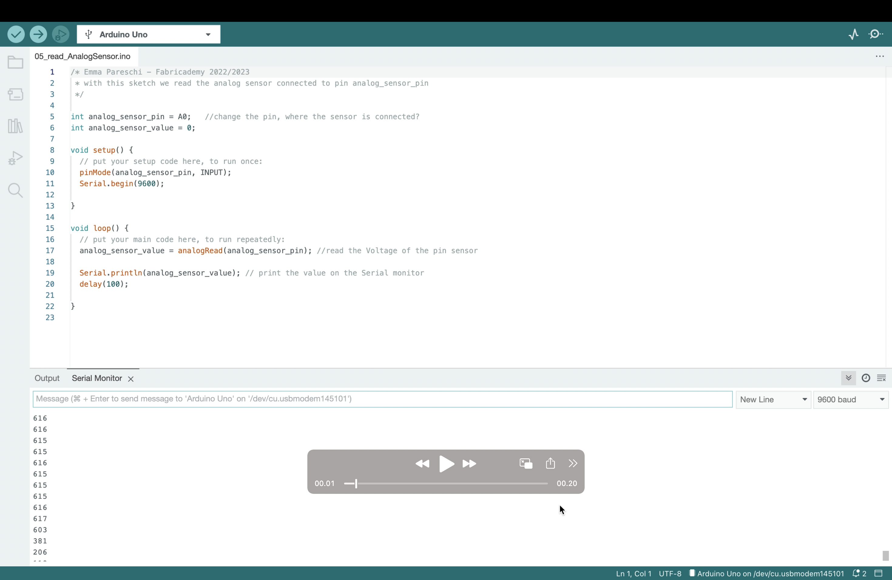
ANALOG SENSOR
/* Emma Pareschi - Fabricademy 2022/2023
 * with this sketch we read the analog sensor connected to pin analog_sensor_pin
 */

int analog_sensor_pin = A0;   //change the pin, where the sensor is connected?
int analog_sensor_value = 0;

void setup() {
  // put your setup code here, to run once:
  pinMode(analog_sensor_pin, INPUT);
  Serial.begin(9600);

}

void loop() {
  // put your main code here, to run repeatedly:
  analog_sensor_value = analogRead(analog_sensor_pin); //read the Voltage of the pin sensor

  Serial.println(analog_sensor_value); // print the value on the Serial monitor
  delay(100);

}
Fabrication files
-
File: DIGITAL SENSOR ↩
-
File: ANALOUG SENSOR ↩
-
File: BROTHER KNITTING MACINE 950 ↩
-
FILE: OPEN SOFTWEAR ↩