FABRICADEMY WEEK5 EXPECTED LEARNING OUTCOMES

Understand how we can produce soft circuits, sensors and actuators.
Learn how to embed them in garments, soft objects or wearables.
Study and learn soft-hard connections.
Discover necessary materials, components, tools.
Explore and replicate existing projects.
FABRICADEMY WEEK5 ASSIGNMENT

Build at least one digital and one analogue soft sensors, using different materials and techniques.
Document the sensor project as well as the readings got using the AnalogRead of Arduino.
Integrate the two soft sensors into one or two textile swatches using hard soft connections.
Document the circuit and it’s schematic.
Document your swatches.
Upload a small video of the swatches functioning.
EXTRA POINT Integrate the swatch into a project.
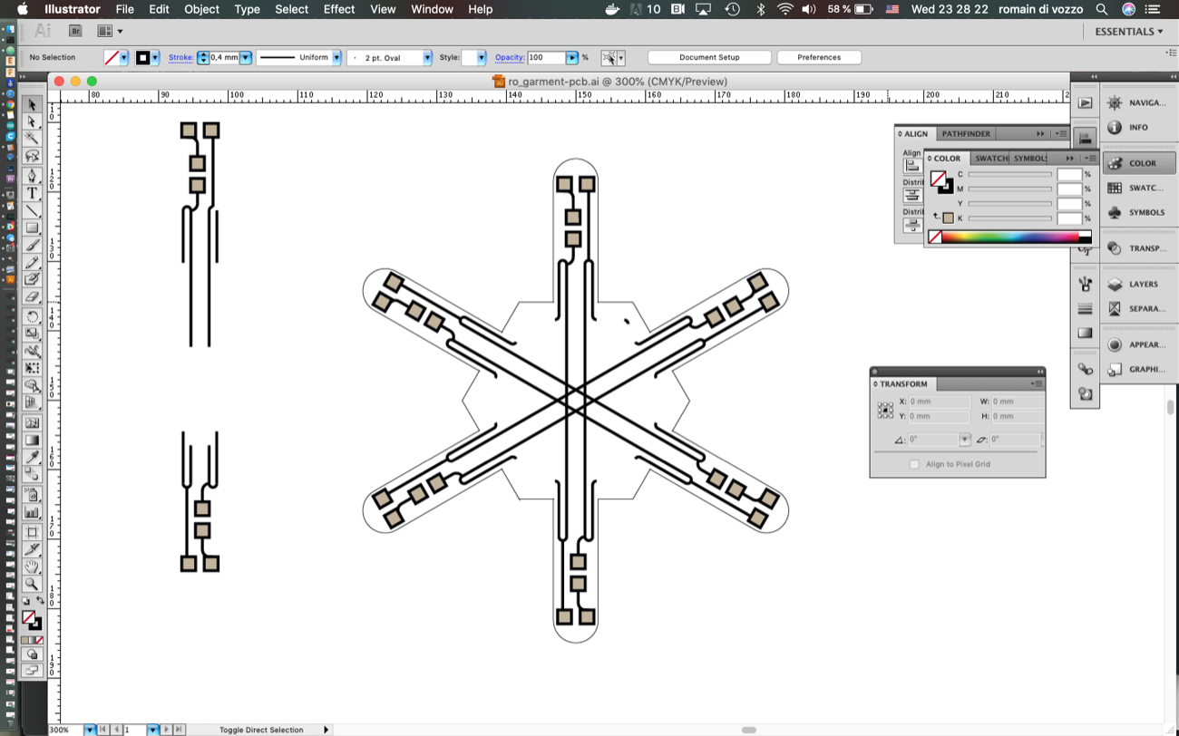
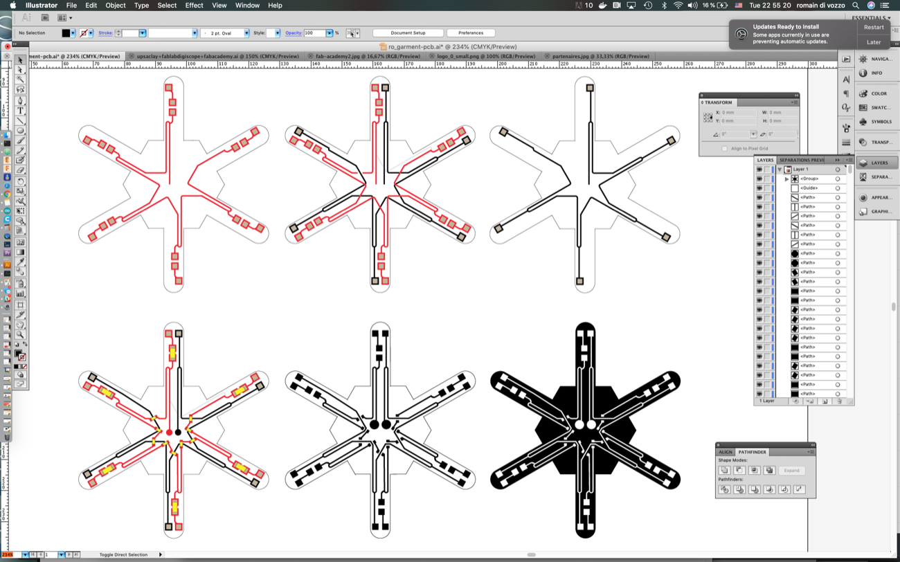
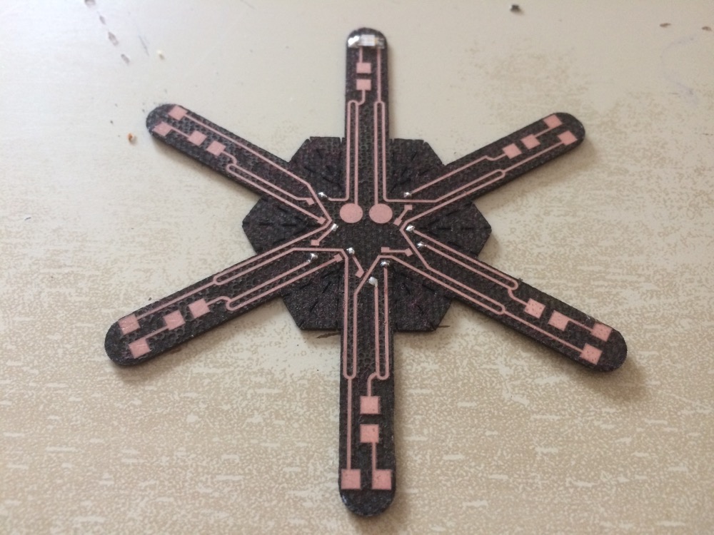
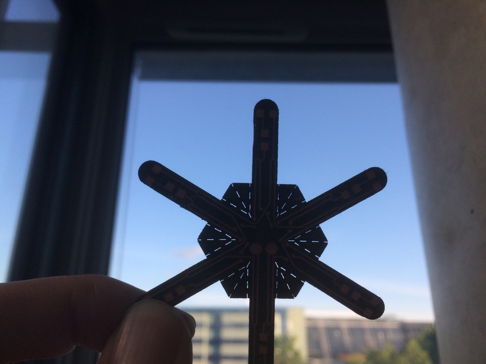
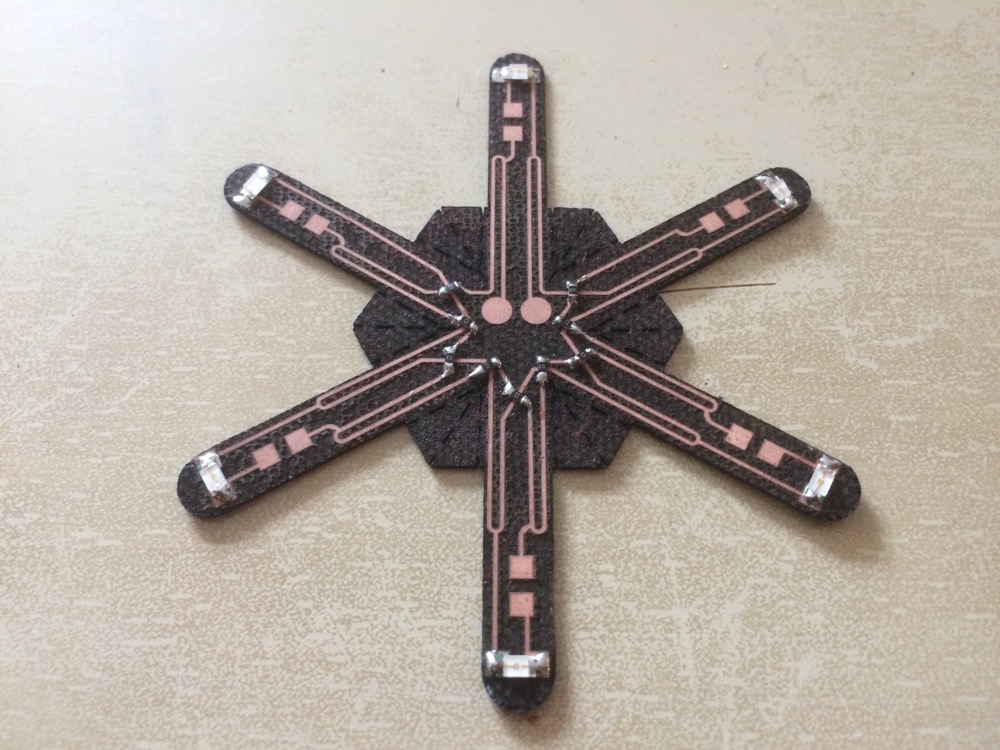
1 | Designing a semi-flexible/soft Star-like-Pattern PCB as LED Array to insert in my leather garment |
I want to design a PCB - flexible or not - that would fit into my garment. It would be a star-like LED array, with the battery and the switch in the middle.
The constraints are related to the standard size of the modules I have defined (even if they are parametric).
Drawing PCB
Drawing PCB
Drawing PCB
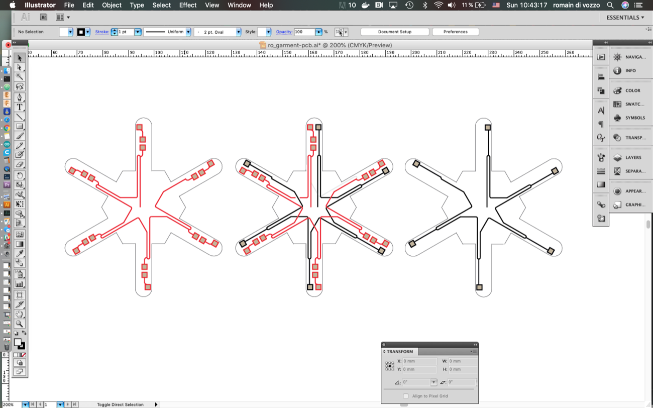
Another set of constraints comes from the pdb design itself. The line width of the circuit, the size of the pads related to the components I will put on it, all these factors impact the design of my PCB.
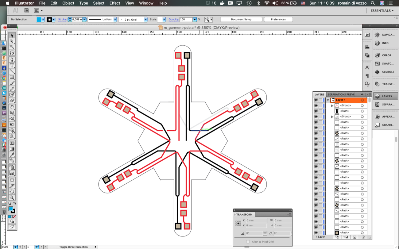
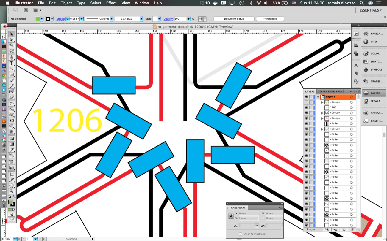
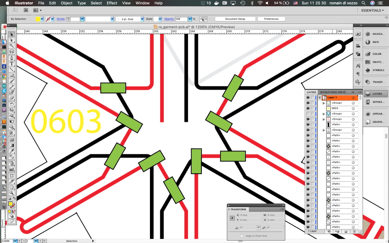
Below you can see the imprint of the 0 ohm resistors I am planning to use as bridges to keep my circuit single-sided. If you want your design to look good it is harder because the logics of electronics deeply obeys to the laws of physics. Keeping my Star-Like design visible after adding the electronic components requires to constantly modify the PCB.
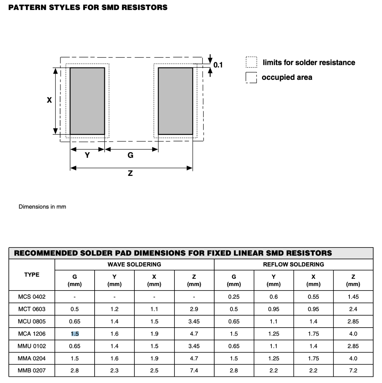
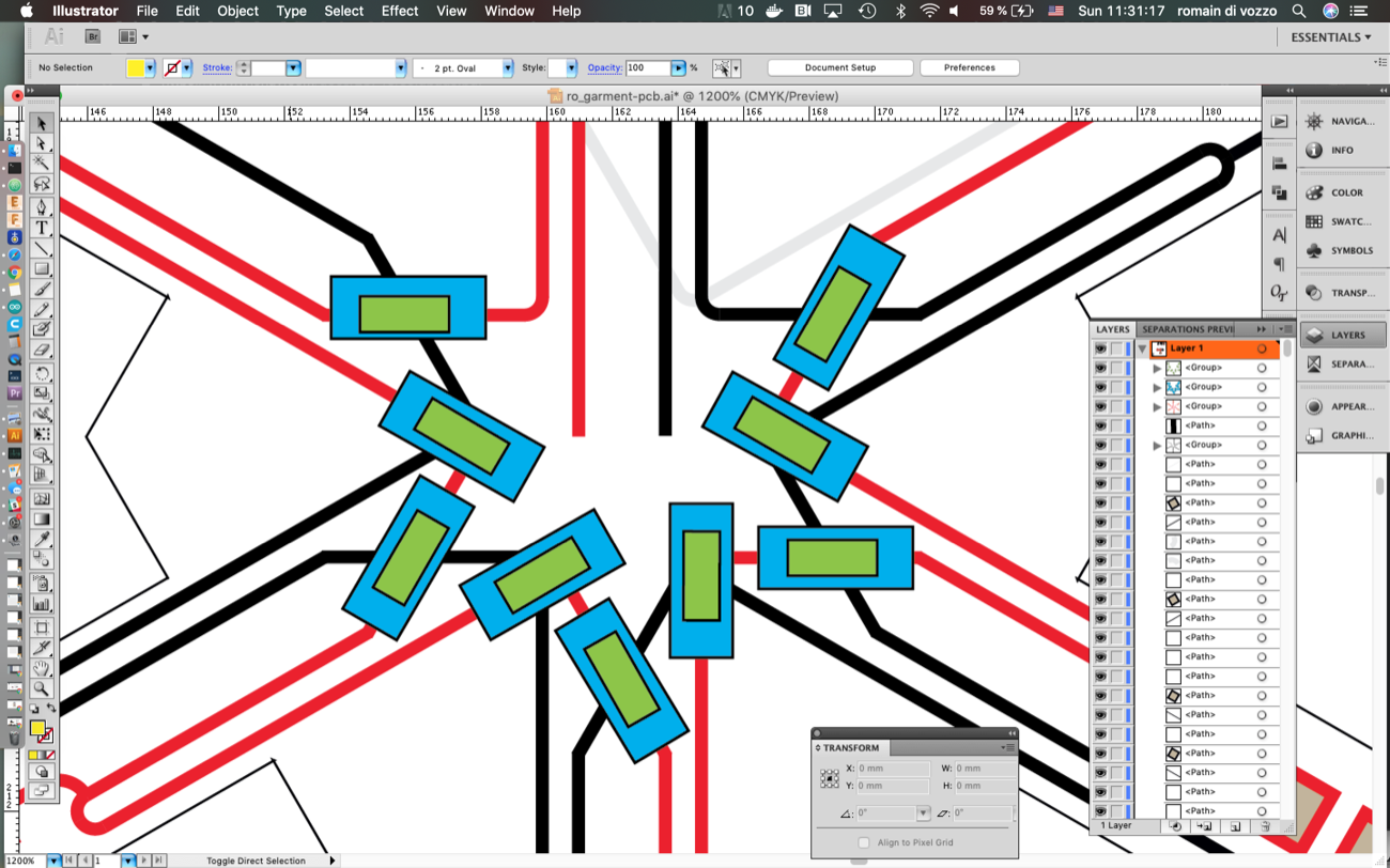
Pattern Styles for SMD resistors
Pattern styles for pads receiving 1206, 0805, 0603, 0402 resistors
Drawing PCB
Drawing PCB
Drawing PCB
PCB with 1206 components
PCB with 0603 components
the imprint is different between 1206 and 0603 components
Drawing PCB
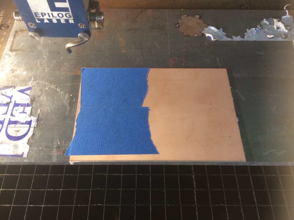
Isolating parts of the PCB
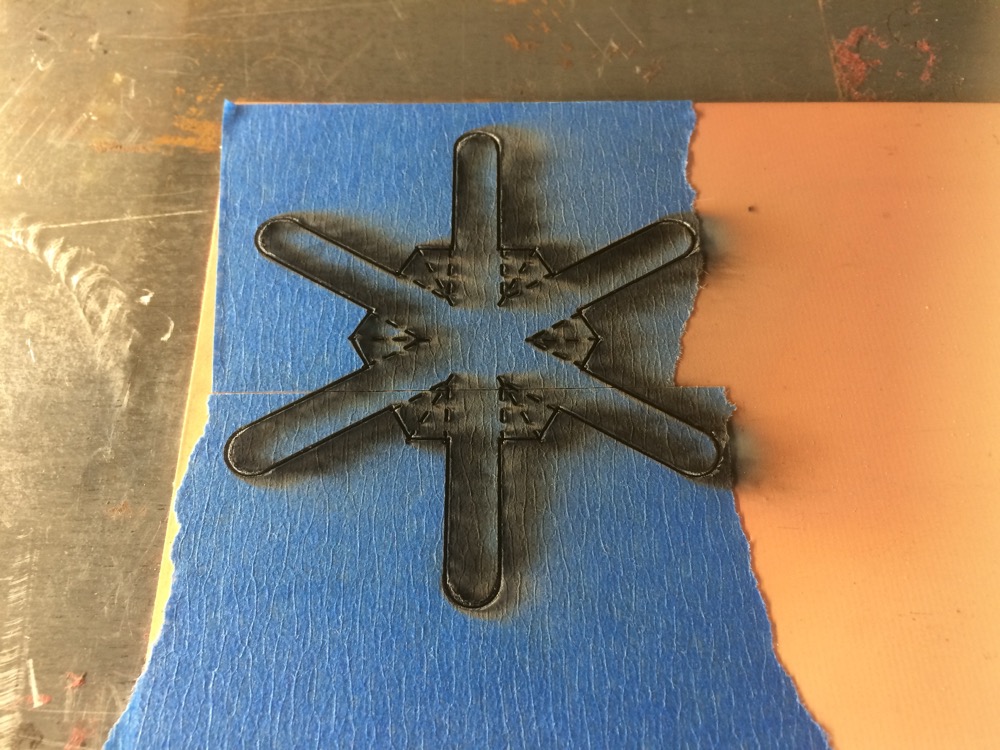
Laser-cutting the PCB
Laser-cutting the PCB
Laser-cutting the PCB
x
x
x
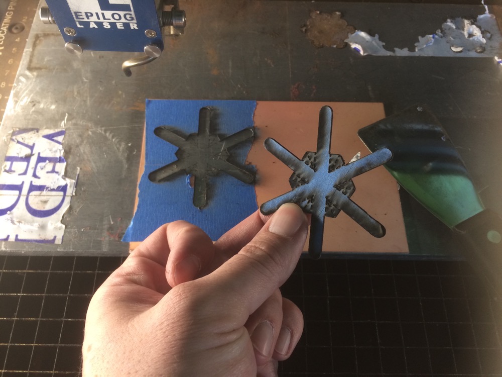
Laser-cutting the PCB
Laser-cutting the PCB
Laser-cutting the PCB
x
x
x
Laser-cutting the PCB
x
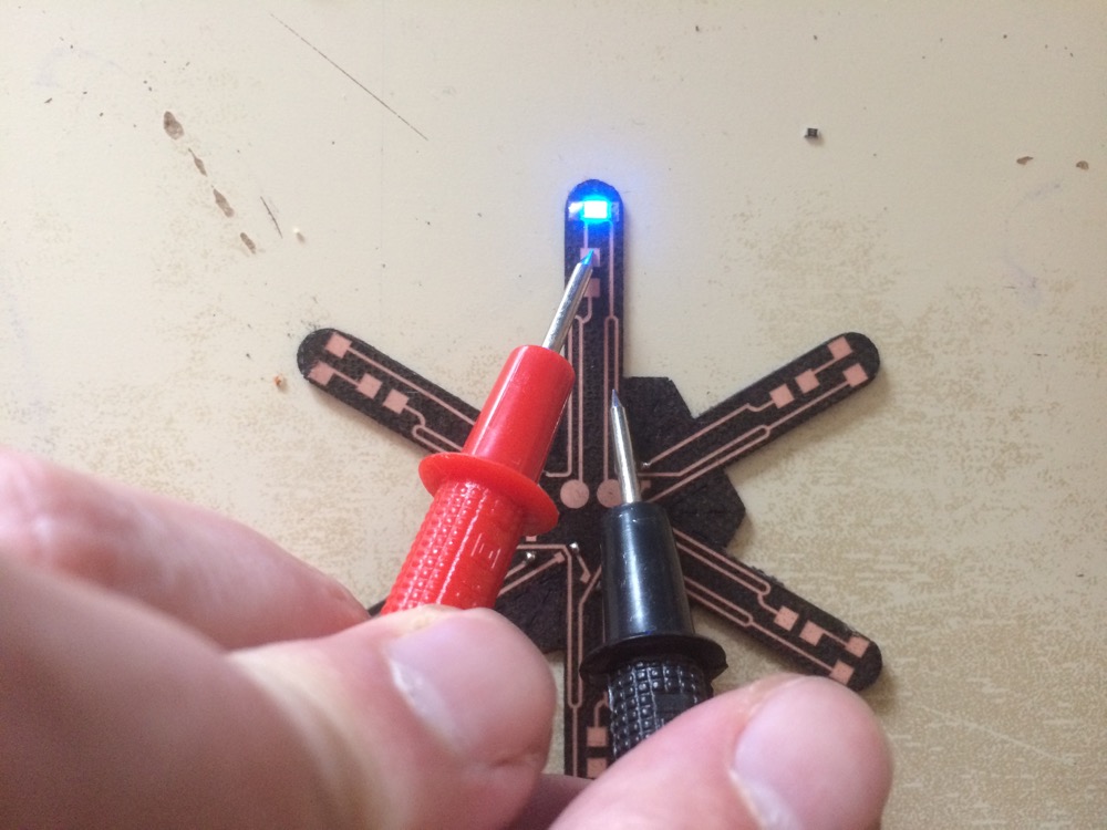
To get a flexible PCB I used a thinner FR4 (.8MM thick) and I have added flextures to it. This one fits perfectly on my garment (pix to add) and shows very bright Blue LEDs.
Adding a completely different type of flexible sensor would be nice. For example, adding stretch/resistive soft sensors to the borders of my garment would be interesting to measure the dimensional variations of an objects that’s wrapped into it. Not enough time to experiment on this right now unfortunately.
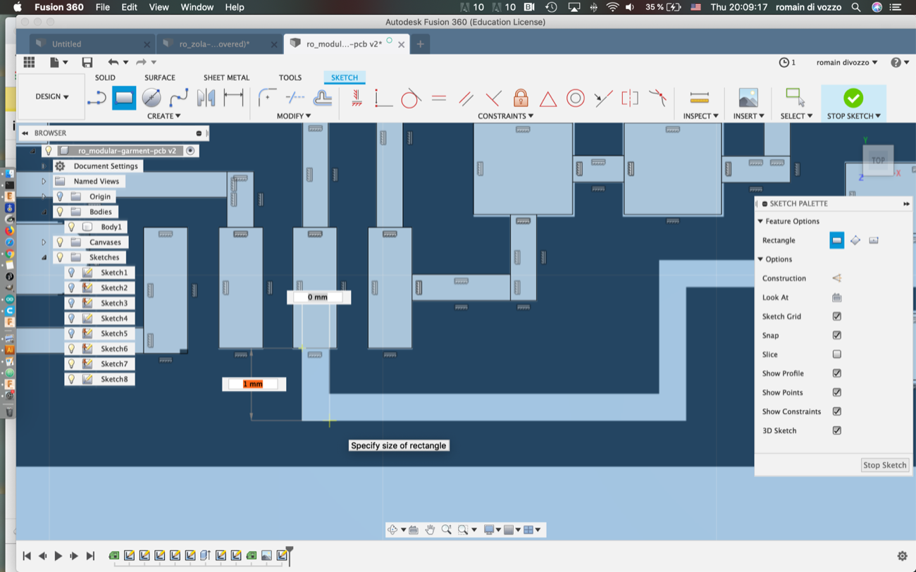
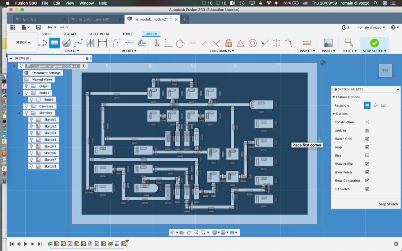
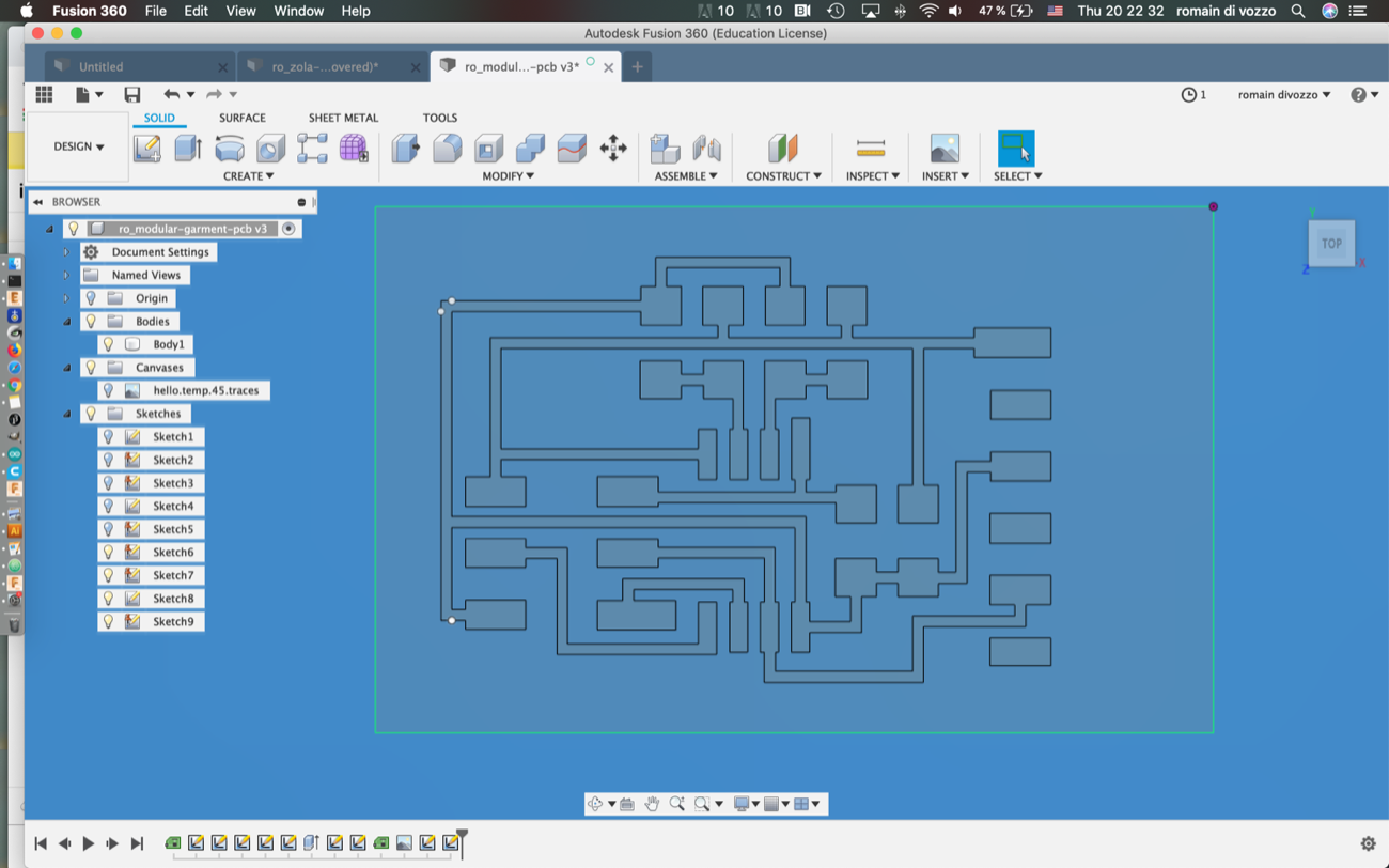
I have been thinking of this for months but couldn’t find the time to seat down and work on it. First, I need to compare sizes between a common Temp Sensor Board and my garment’s pattern. I’ll do it with Fusion 360, as it is a very precise tool if you want to measure things and the space between them. It would also have been possible to redesign the PCB entirely as Fusion and Eagle (PCB Design software) are now connected.
Redrawing the PCB from an existing board
Redrawing the PCB from an existing board
Redrawing the PCB from an existing board
Redrawing the PCB from an existing board
Redrawing the PCB from an existing board
Redrawing the PCB from an existing board
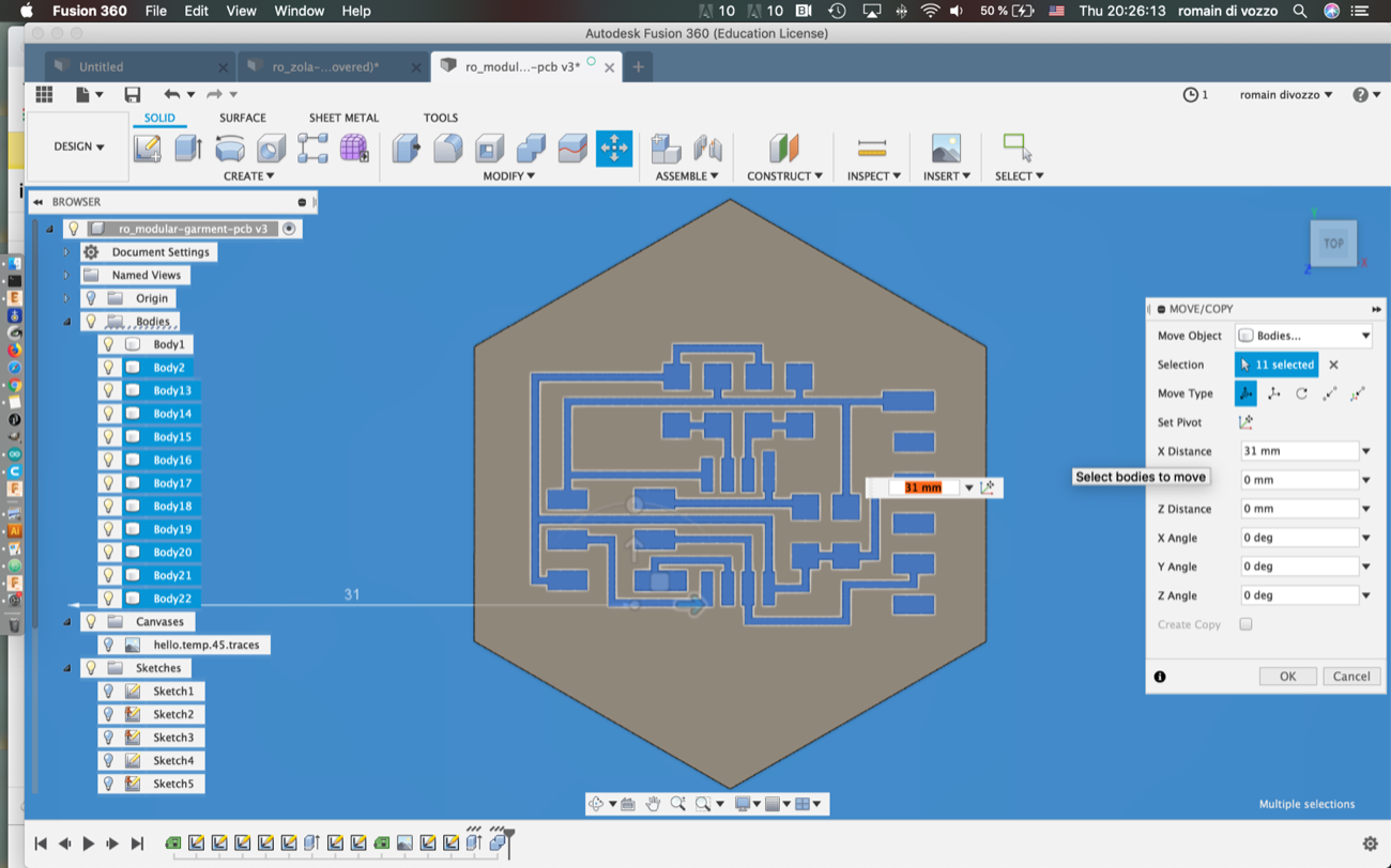
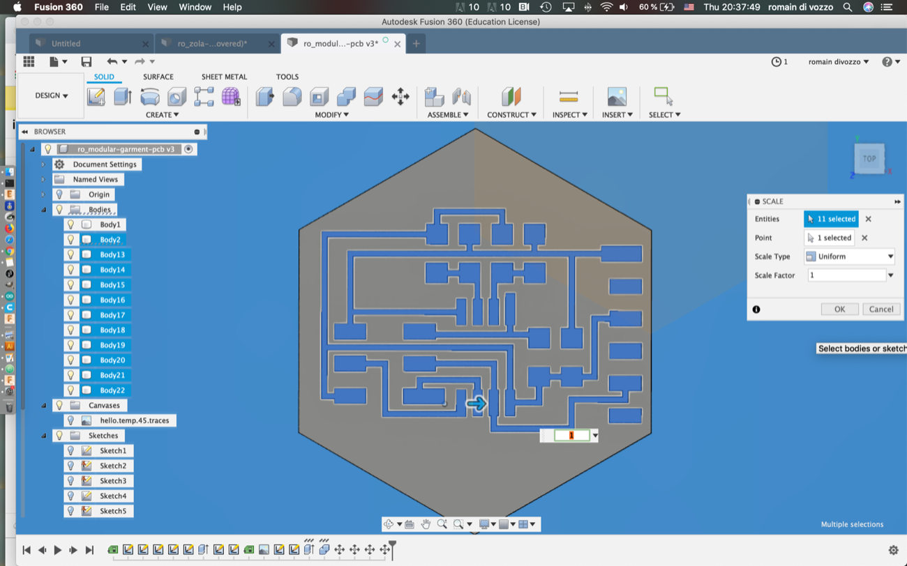
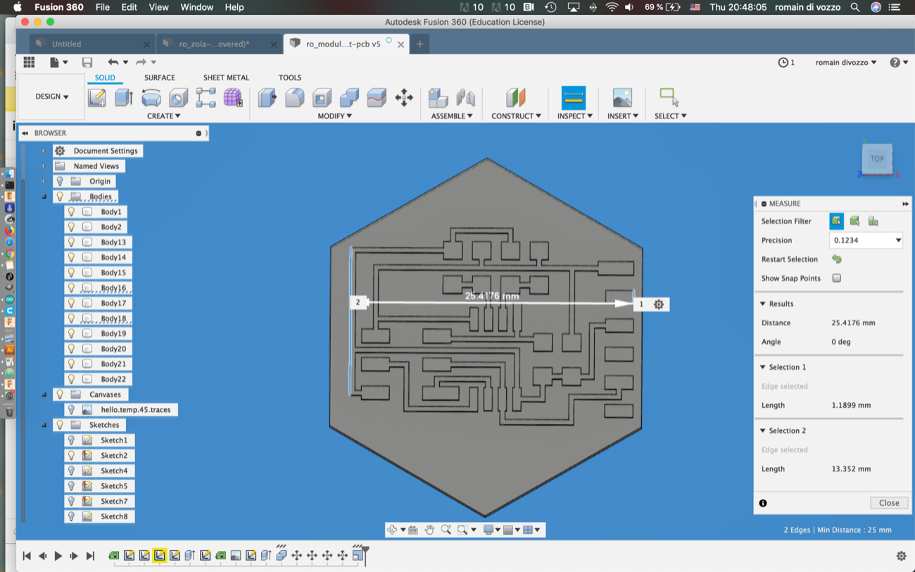
Rescaling isn’t easy when it applies to PCBs. The reason is that electronic components come into packages - meaning: a type of box and pins arranged around the components to make them meet with standard sizes and distances with a very low tolerance. This are both production and then design standards that you can’t ignore when you design or modify a PCB. As you will see below, I’ve used an existing copy of the Temp Sensor Board I want to modify and measured parts of it with calipers to make sure to rescale the PCB drawing as close as possible to reality.
Adjusting Scale between PCB and Garment
Adjusting Scale between PCB and Garment
Adjusting Scale between PCB and Garment
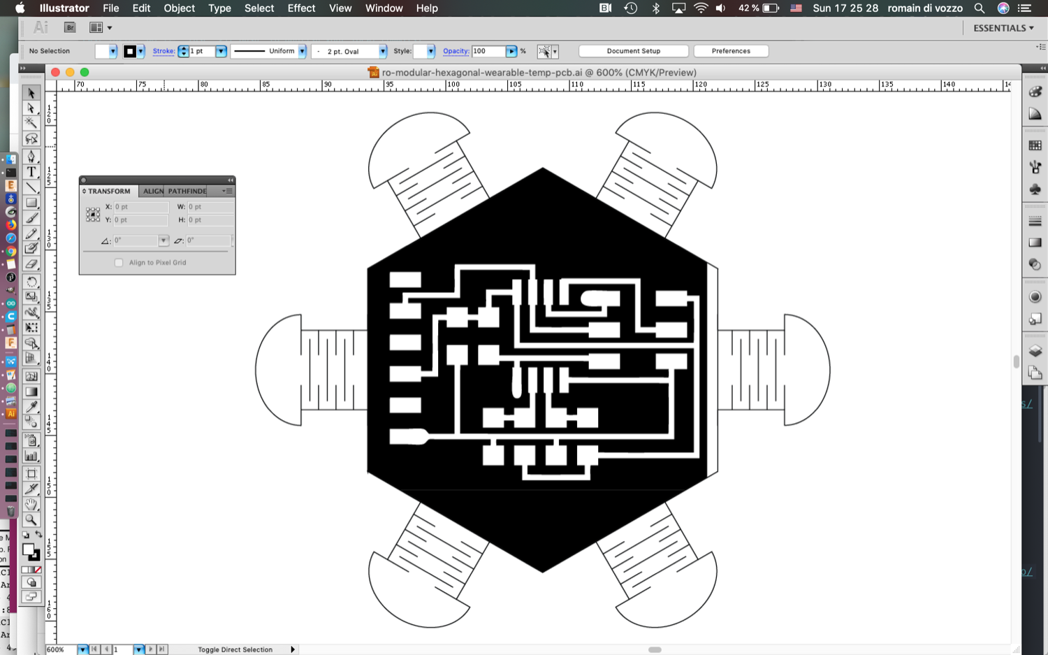
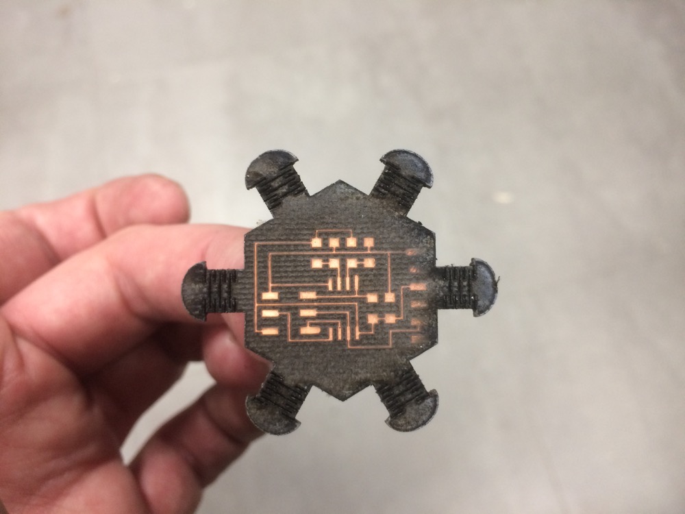
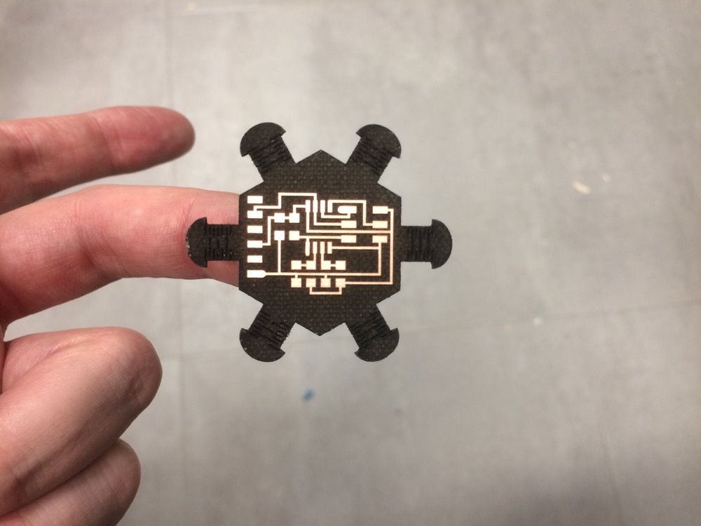
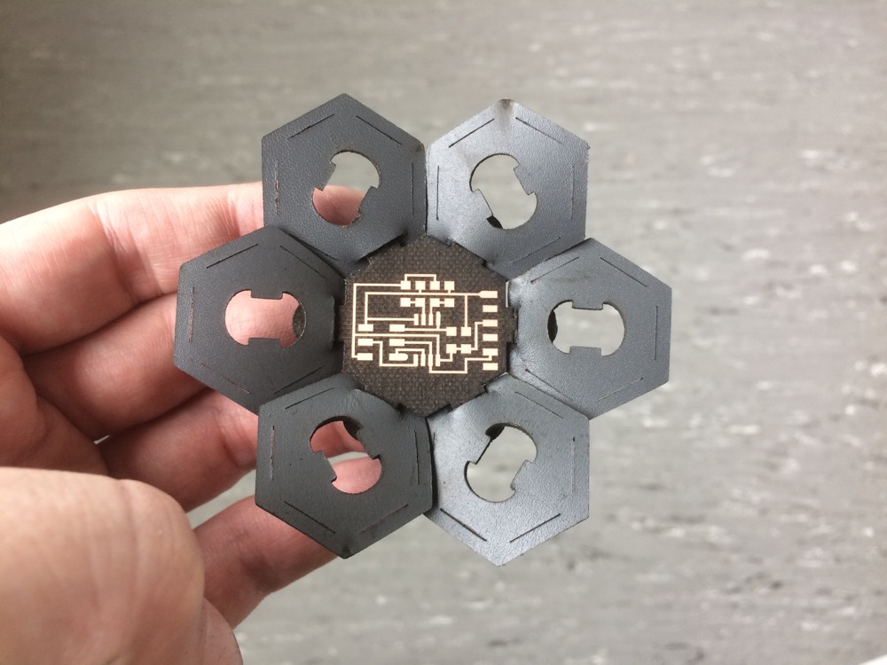
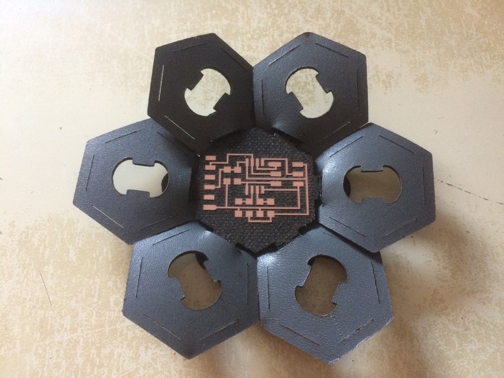
3 | Adapting PCB shape to Garment’s Modules with Adobe Illustrator |
I want to embed a Temp Sensor design (from Neil Gershenfeld) to my garment modular design. I added the connections on the design to assemble it with the rest of the garment directly. I added flextures on the PCB to give it a bit of flexibility, since this FR4 board is made of epoxy (1.6mm) and is very rigid.
Adapting PCB Design to hexagonal shape
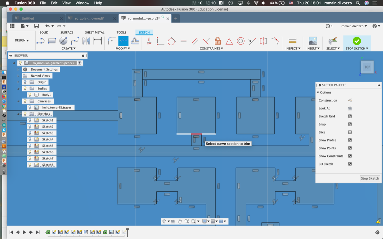
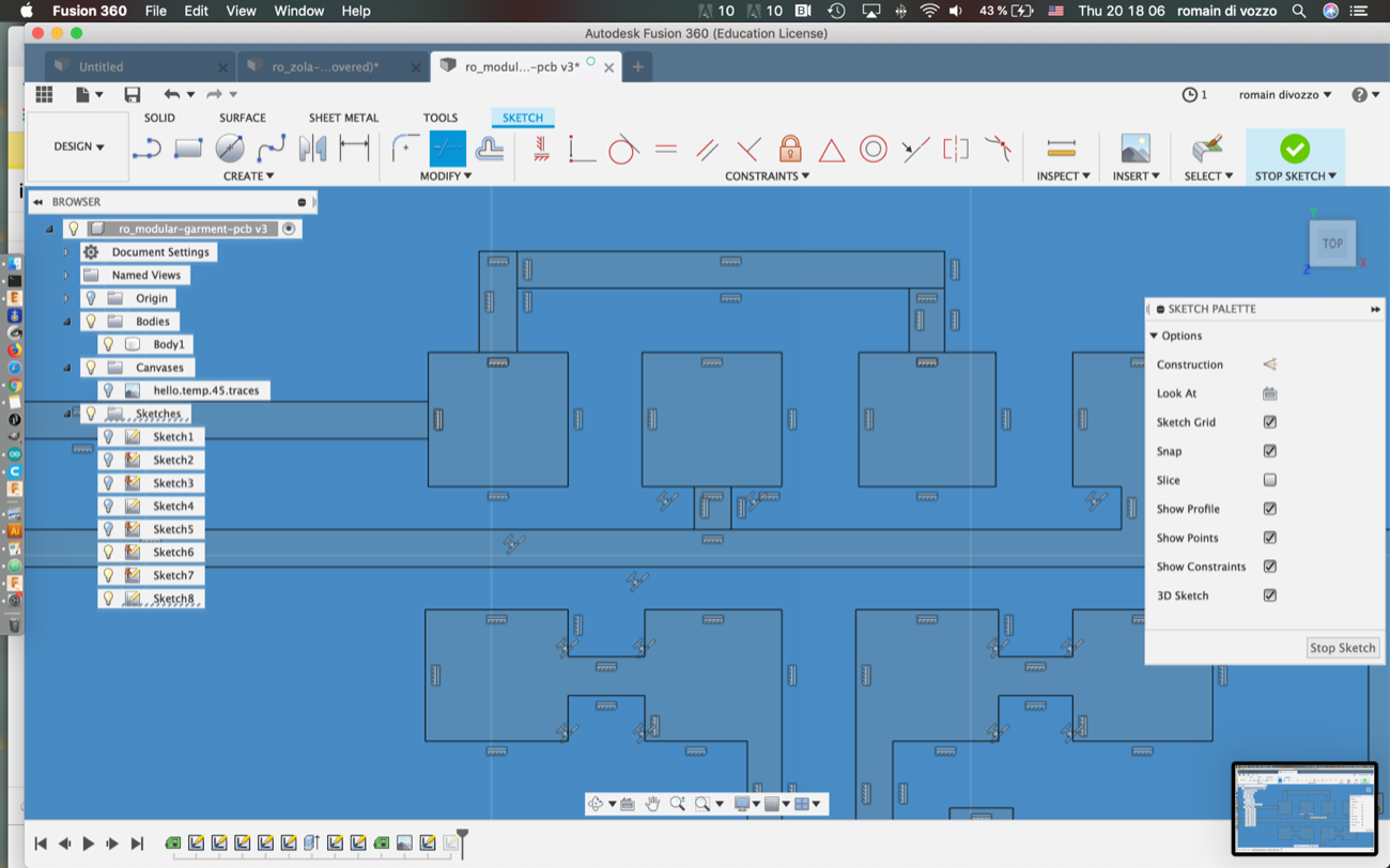
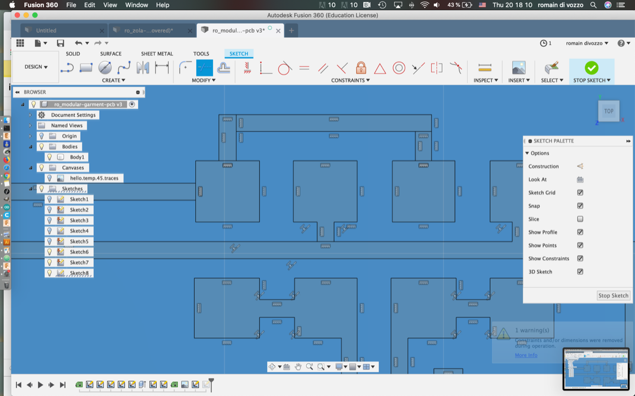
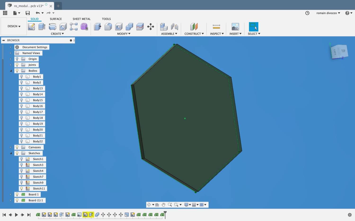
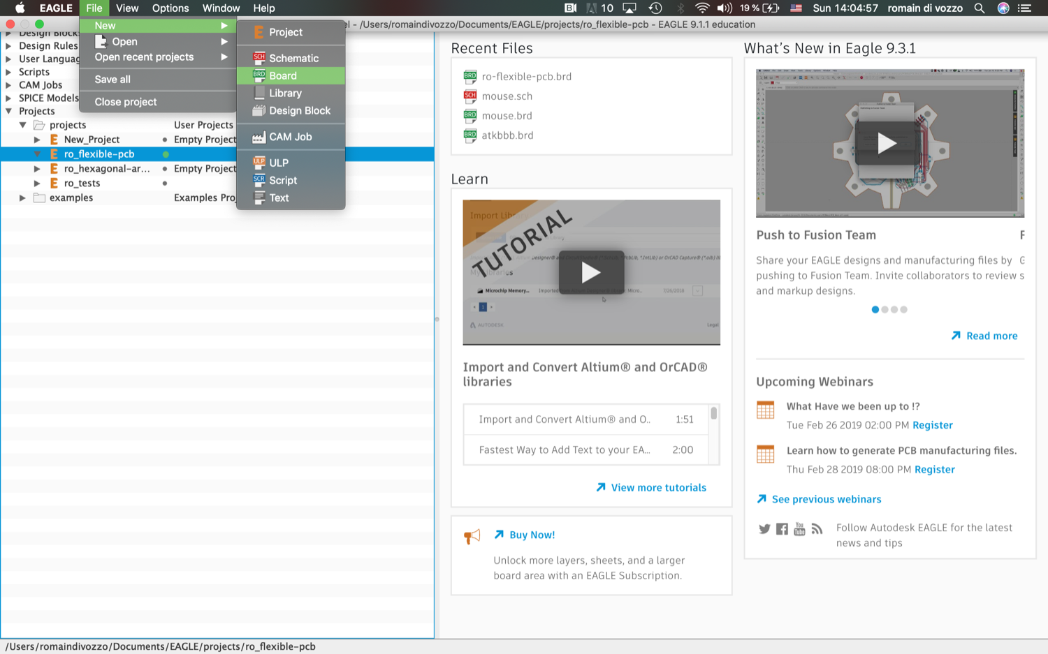
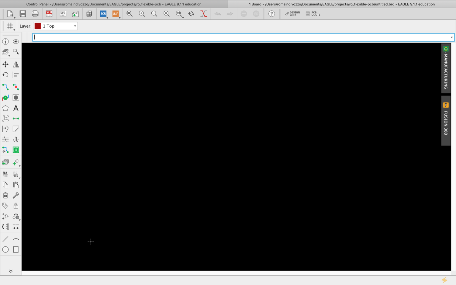
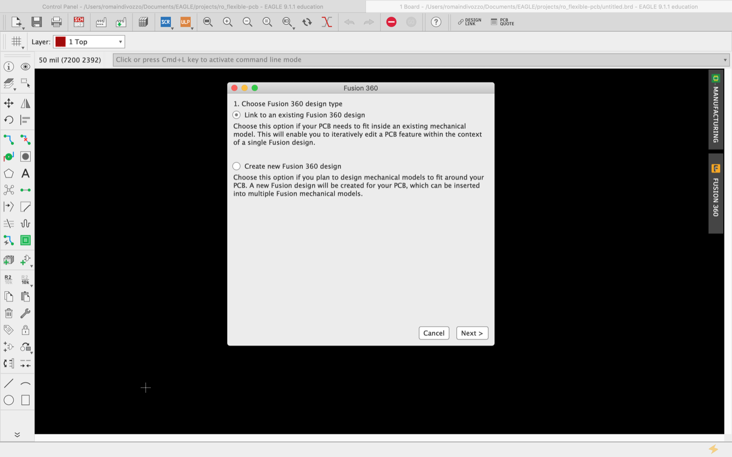
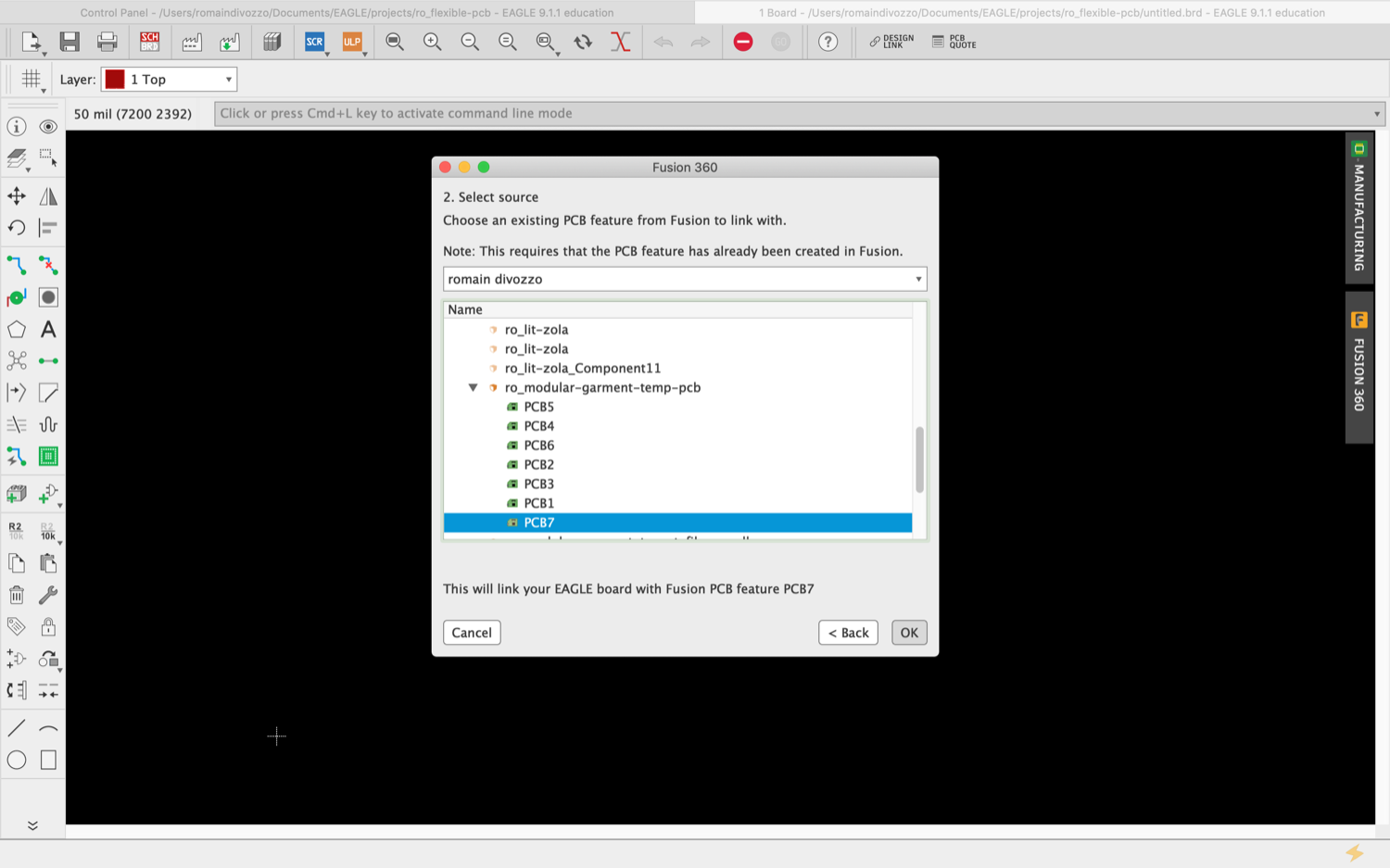
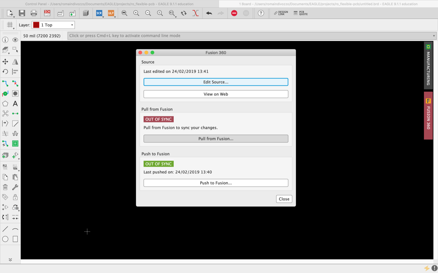
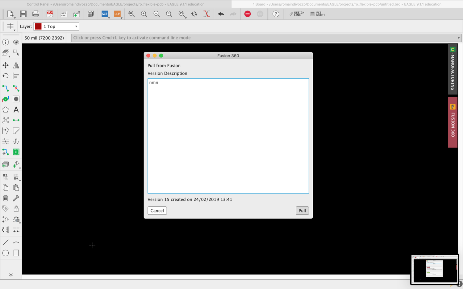
4 | Adapting PCB Designto an Hexagonal module with FUSION 360 and EAGLE |
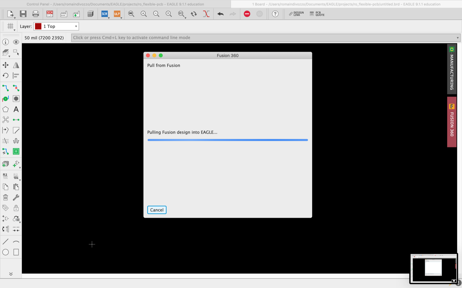
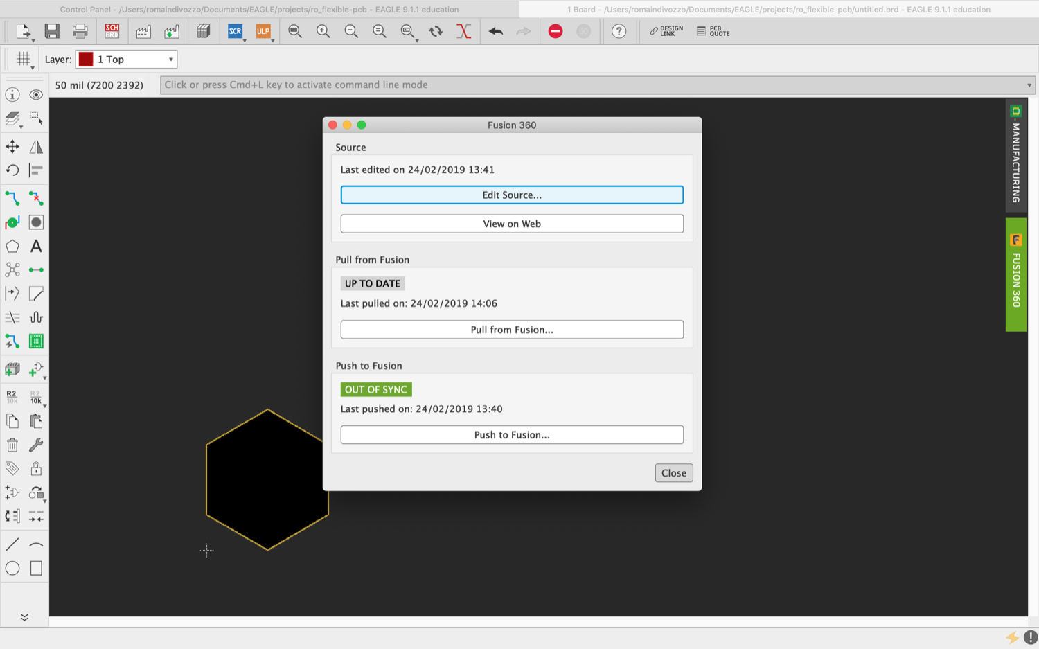
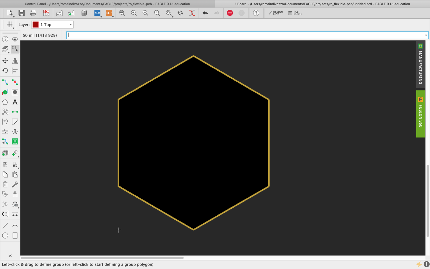
Linking a PCB Outline between Fusion360 and Eagle
Linking a PCB Outline between Fusion360 and Eagle
Linking a PCB Outline between Fusion360 and Eagle
Linking a PCB Outline between Fusion360 and Eagle
Linking a PCB Outline between Fusion360 and Eagle
Linking a PCB Outline between Fusion360 and Eagle
Linking a PCB Outline between Fusion360 and Eagle
Linking a PCB Outline between Fusion360 and Eagle
Linking a PCB Outline between Fusion360 and Eagle
Linking a PCB Outline between Fusion360 and Eagle
Linking a PCB Outline between Fusion360 and Eagle
Linking a PCB Outline between Fusion360 and Eagle
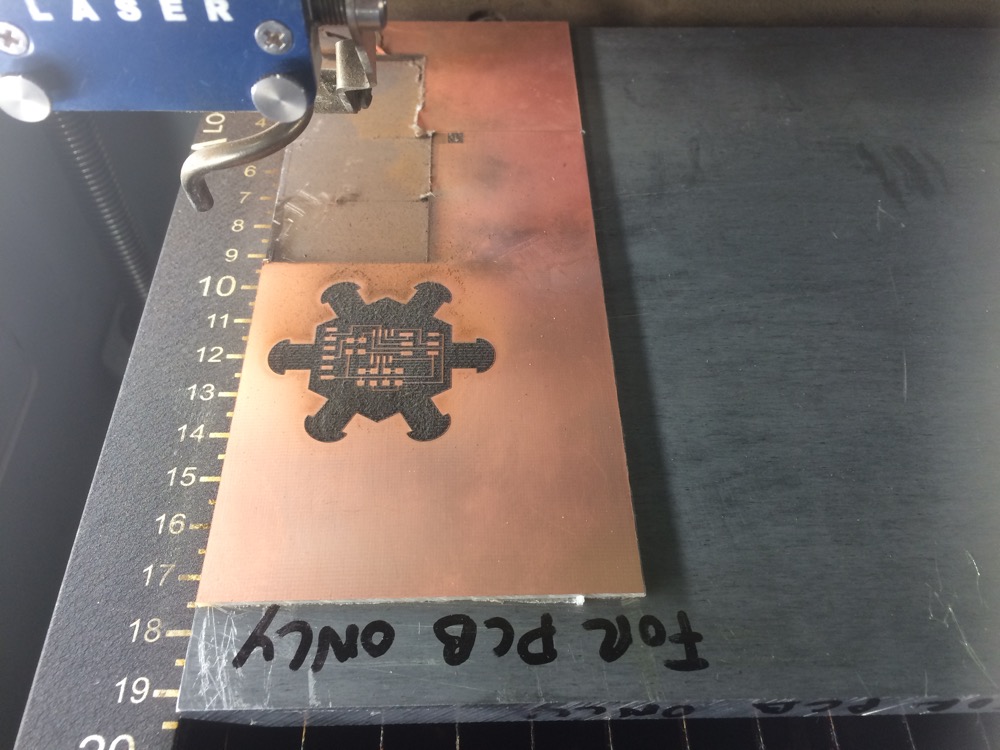
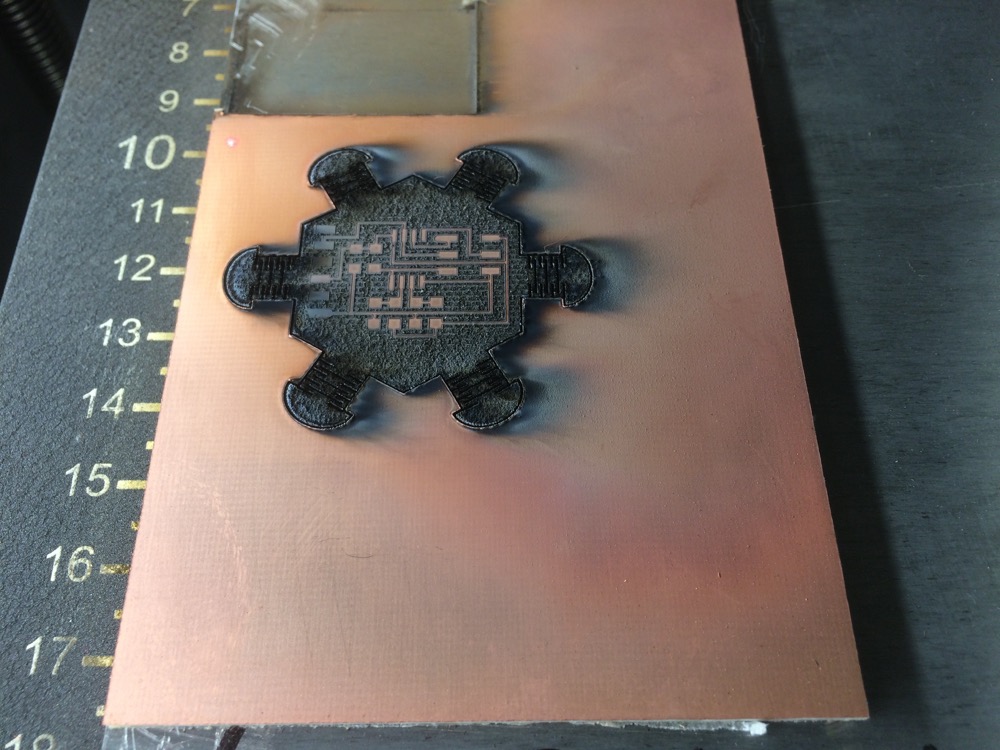
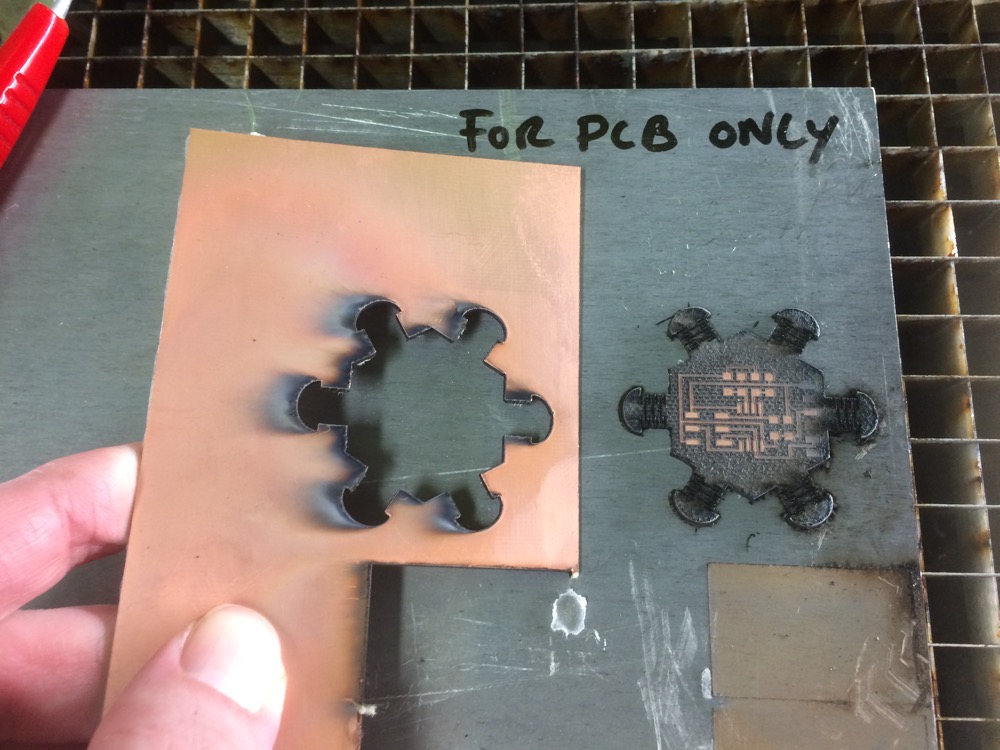
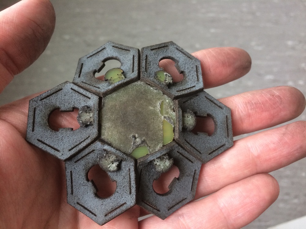
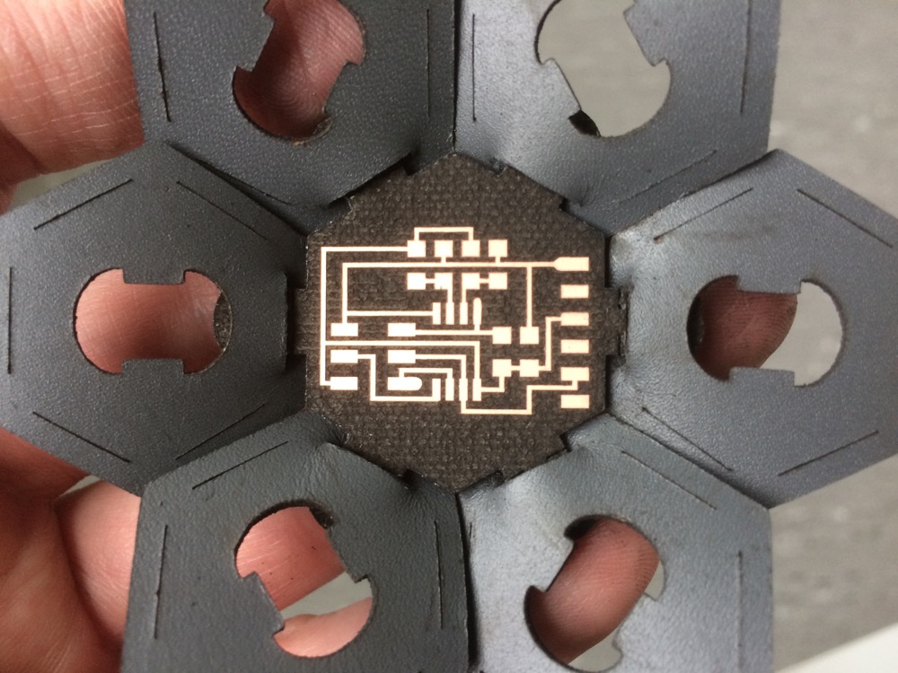
5 | Laser Engraving and Cutting modular Temp-sensor-PCB on Epilog Fusion M2+ |
I want to demonstrate the versatility of this garment and caracterize it as a surface, and eventually as both a passive and interactive surface that interacts with its environment.
a
a
a
a
a
a
a
a
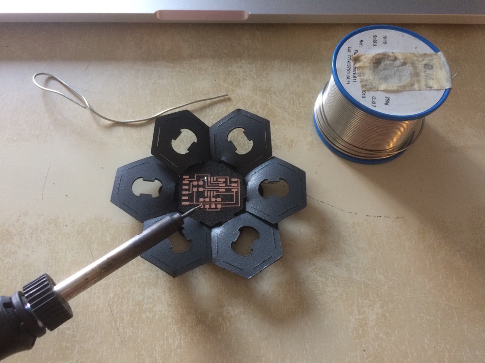
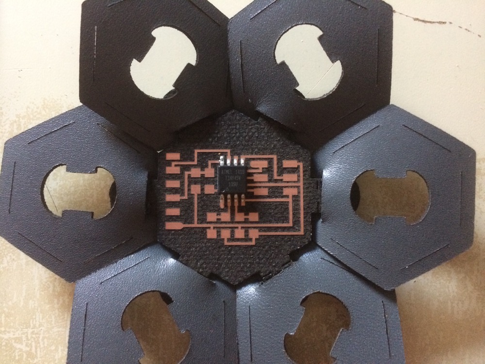
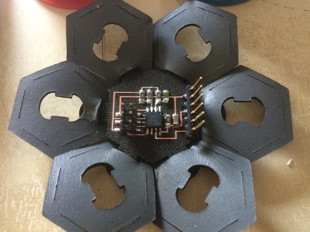
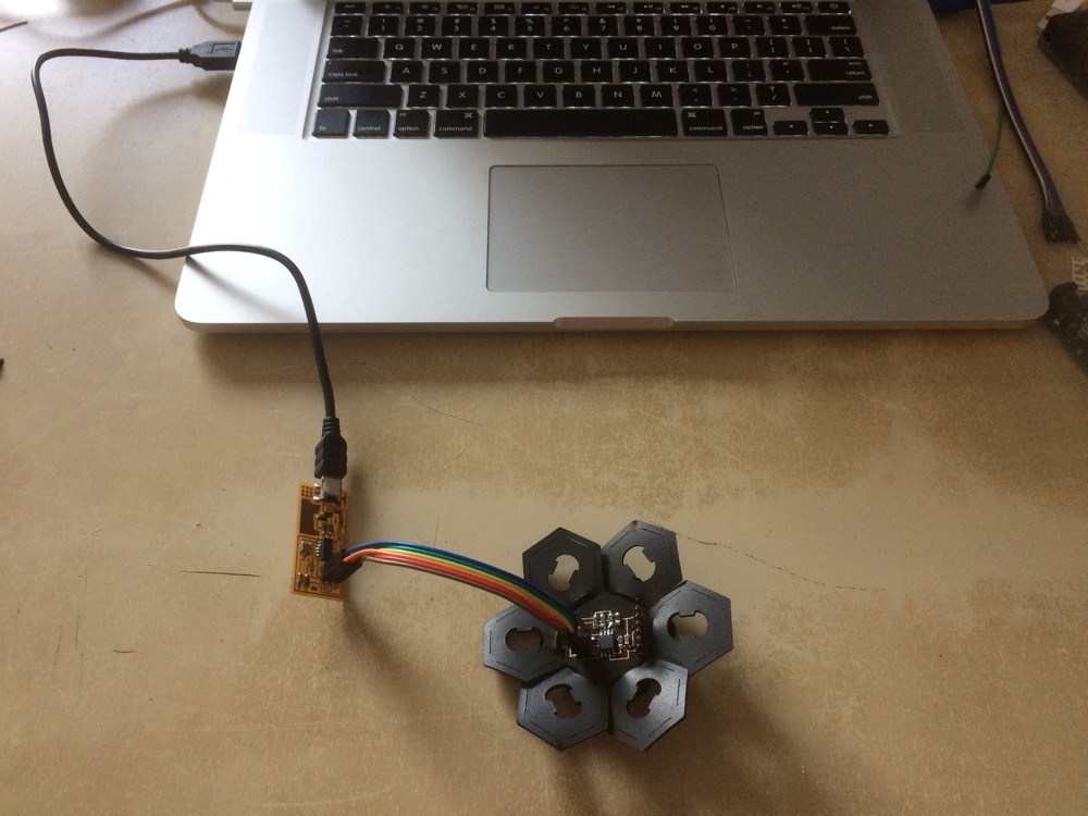
6 | Placing electronic components on the Temp-sensor-Board |
Placing components on the Temp-sensor-board
Placing components on the Temp-sensor-board
Placing components on the Temp-sensor-board
Placing components on the Temp-sensor-board
Placing components on the Temp-sensor-board
Placing components on the Temp-sensor-board
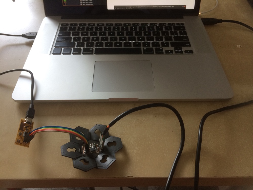
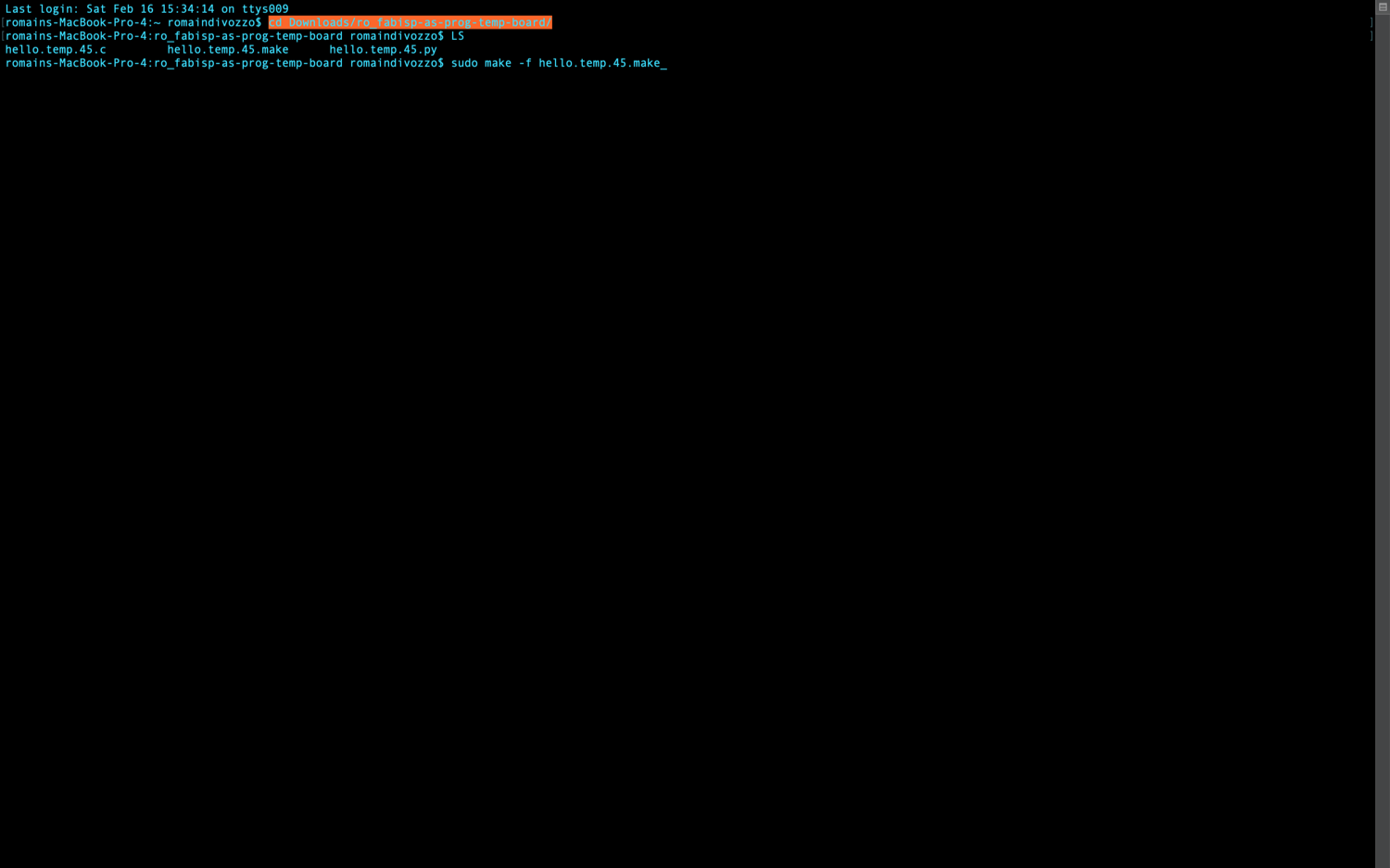
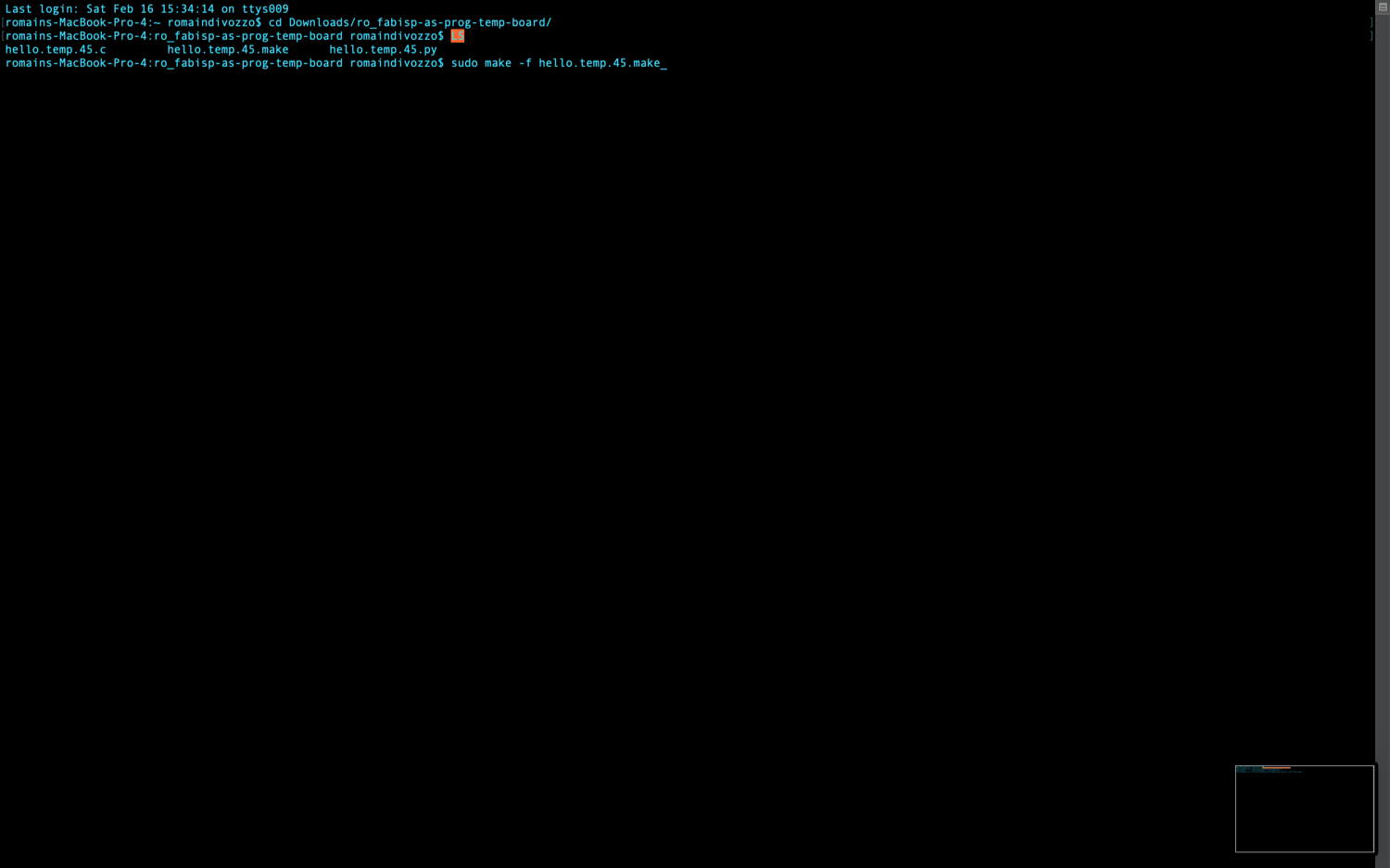
7 | Programming Temp Board with FABISP and AVR DUDE through your Terminal |
1: you go to the Directory where you have your files with the “cd” command and press “Enter”
Programming Temp Board with FABISP - command line 1
romains-MacBook-Pro-4:~ romaindivozzo$ cd Downloads/ro_fabisp-as-prog-temp-board/
2: you list the file you have in this directory with the “ls” command and press “Enter” and the list of files you have in your directory appears underneath
Programming Temp Board with FABISP - command line 2
romains-MacBook-Pro-4:ro_fabisp-as-prog-temp-board romaindivozzo$ LS
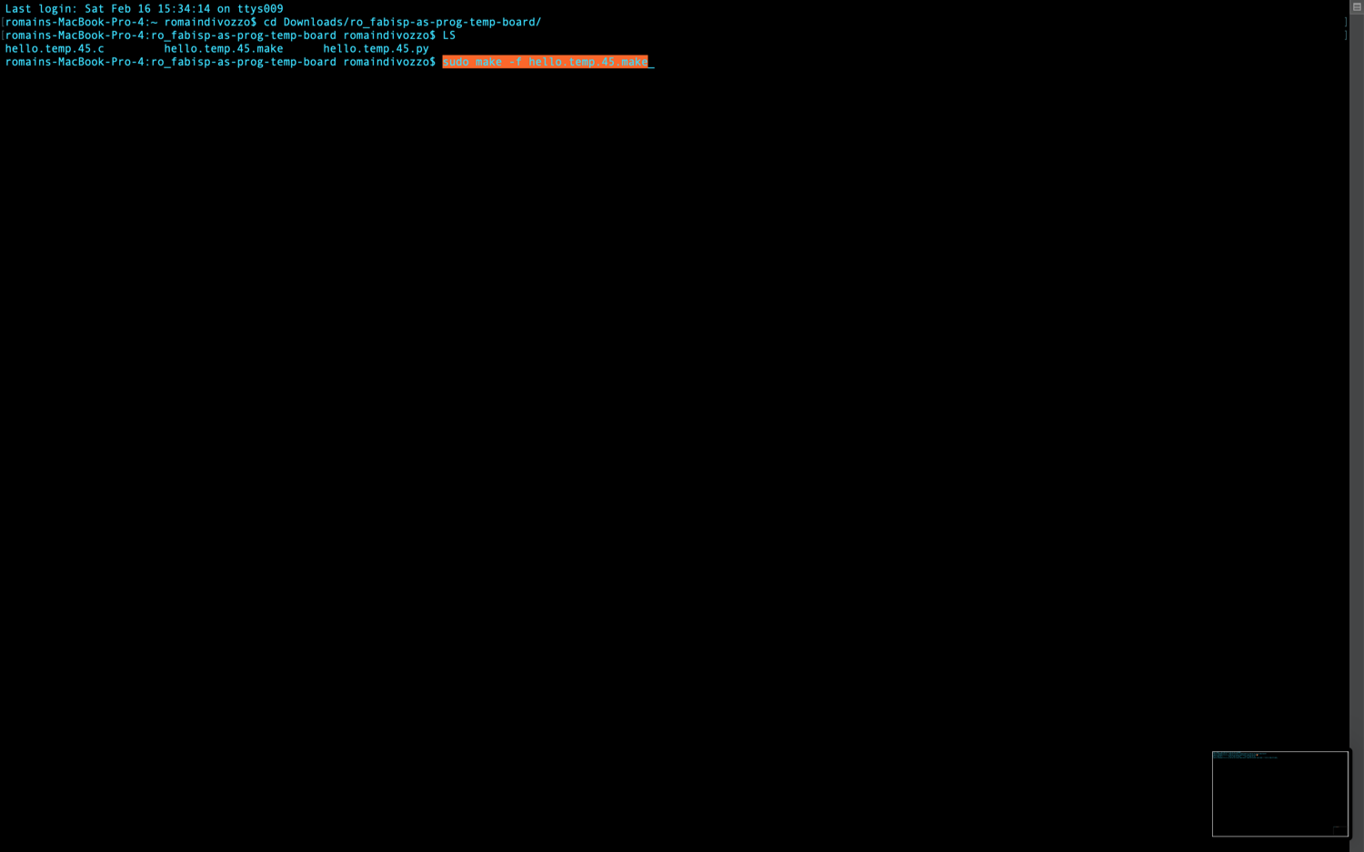
3: you type in the “sudo make -f hello.temp.45.make” command and “Enter” and you are asked to type in your password and “Enter”. when you type your password in it remains invisible
Programming Temp Board with FABISP - command line 3
romains-MacBook-Pro-4:ro_fabisp-as-prog-temp-board romaindivozzo$ sudo make -f hello.temp.45.make
Password:
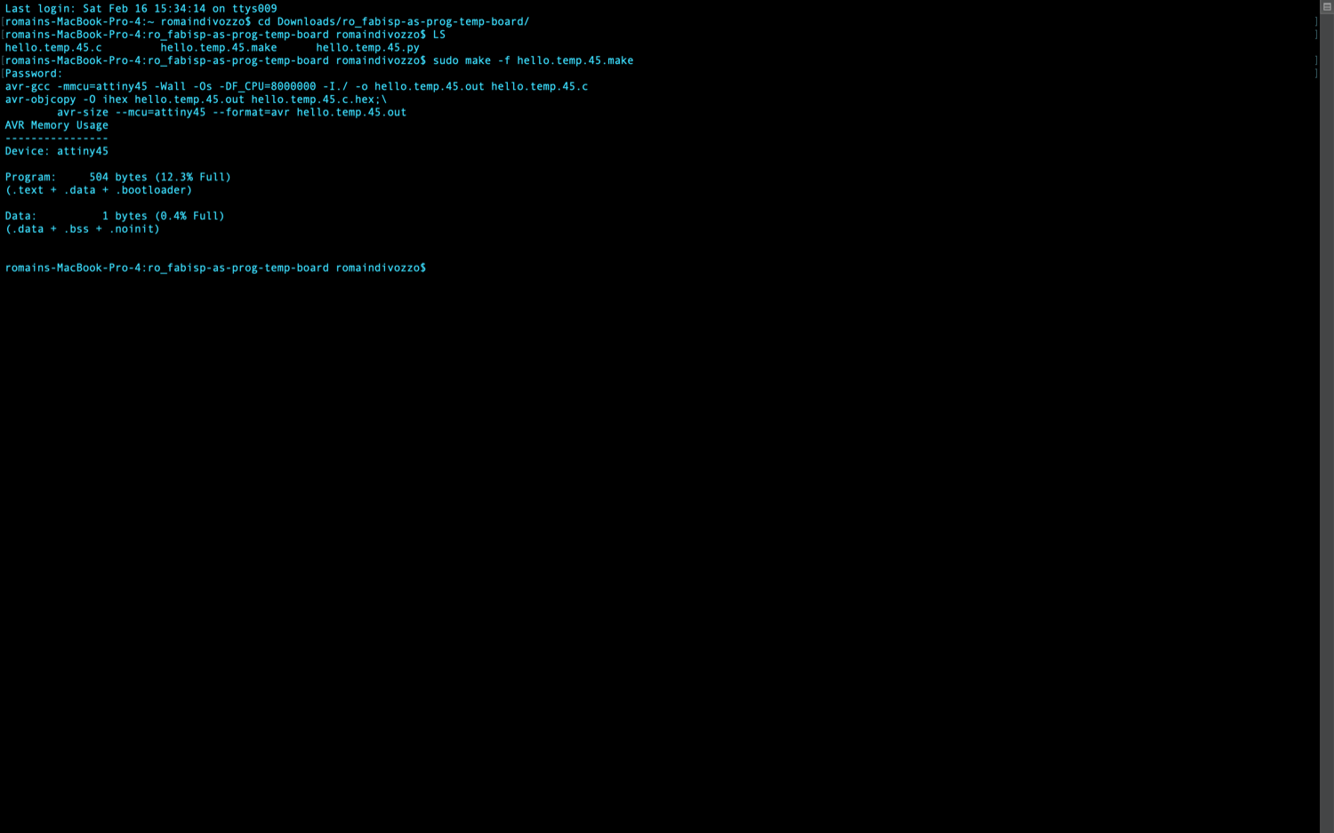
4: after you typed in your password and press “enter”, the following shows up
Programming Temp Board with FABISP - command line 4
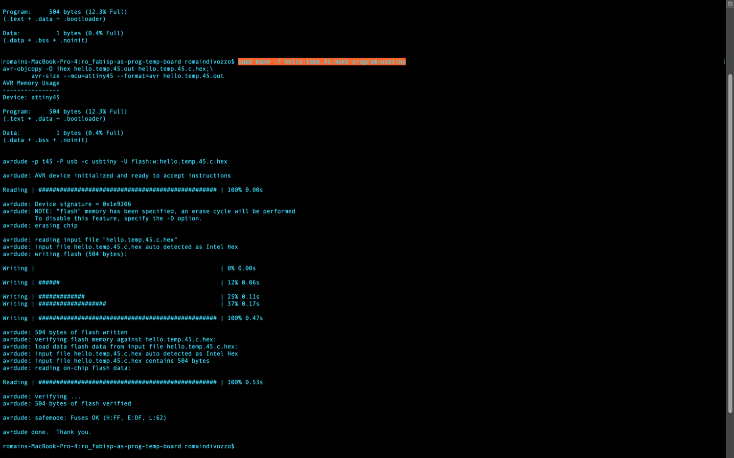
5: then you type in “sudo make -f hello.temp.45.make program-usbtiny” and press “enter”, and the following shows up. This means you successfully programed your board
Programming Temp Board with FABISP - command line 5
romains-MacBook-Pro-4:ro_fabisp-as-prog-temp-board romaindivozzo$ sudo make -f hello.temp.45.make
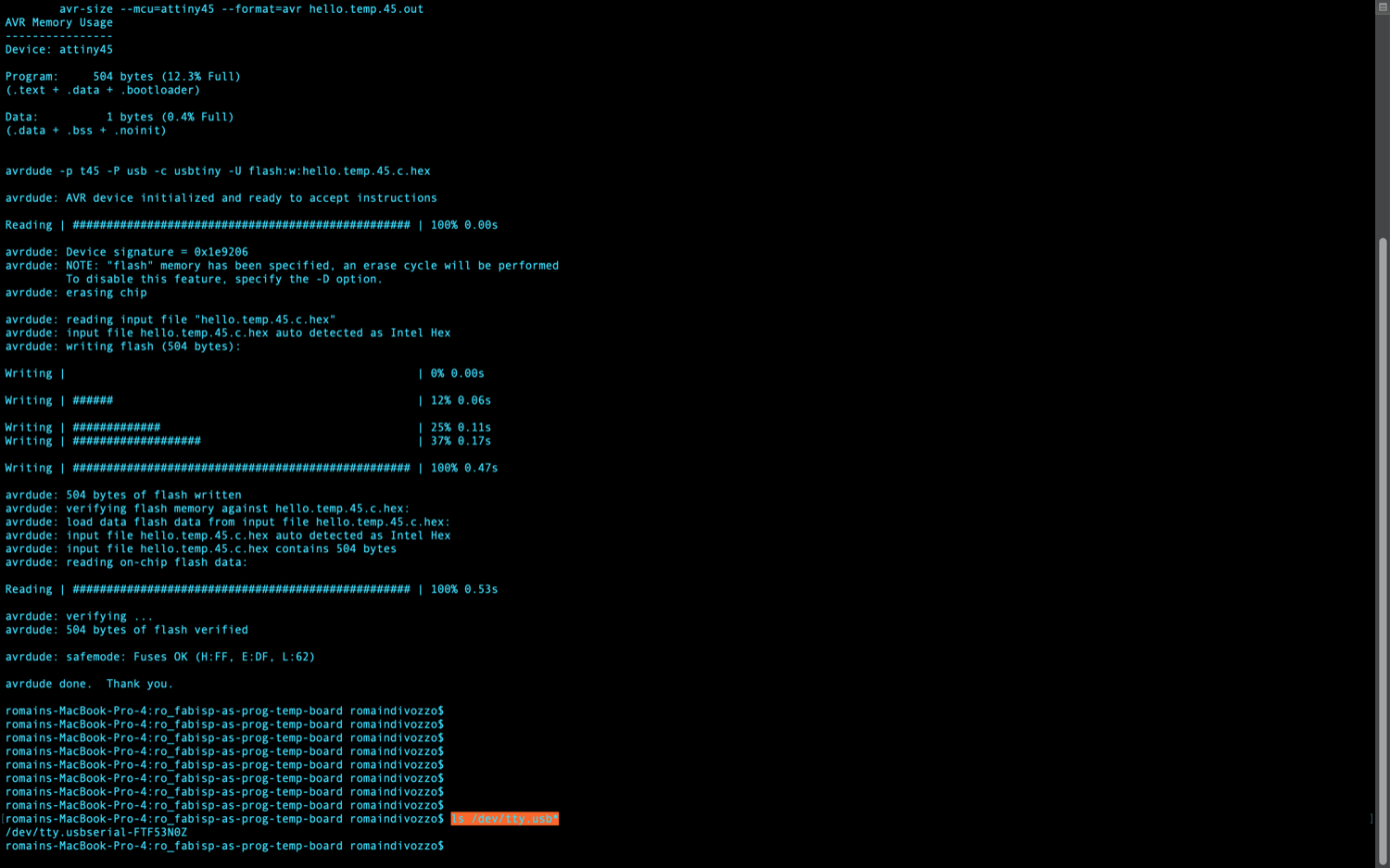
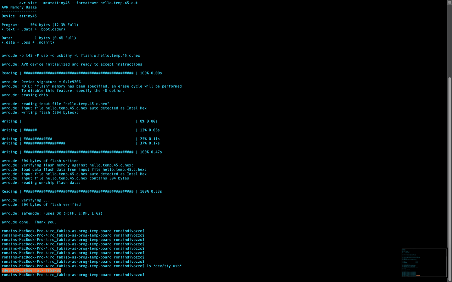
6: then you type in “ls /dev/tty.usb*” to list the usb port ID and press “Enter” to start talking with the port that’s connected to your Temp-sensor-board through the FTDI cable
Programming Temp Board with FABISP - command line 6
romains-MacBook-Pro-4:ro_fabisp-as-prog-temp-board romaindivozzo$ ls /dev/tty.usb*
7: then your usb serial port is displayed
Programming Temp Board with FABISP - command line 7
/dev/tty.usbserial-FTF53N0Z
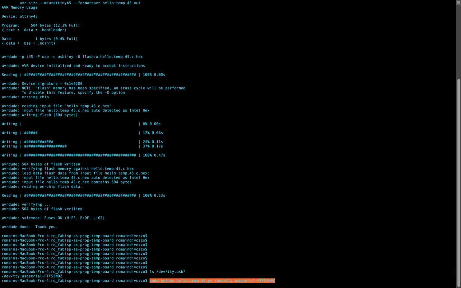
8: then you type in “sudo python hello.temp.45.py /dev/tty.usbserial-FTF53N0Z” and press “Enter” to start the python app that allows you to visualize your sensor
Programming Temp Board with FABISP - command line 8
About my final project: I just had a discussion on the strategies to adopt to embed electronics into my garment while keeping it modular without having to embed too many wires to connect, say, light modules that can vary in brightness to a central board.
-The I2C protocol would be perfect for this because it requires only 2 wires to connect 127 slaves (like slave LEDs). I2C protocol can be developed with a Atmega 328P, I could just make my own hexagonal Arduino en use this protocol to communicate with a lot of LEDs. My doubt is that, with my hexagonal modular pattern the distance between the center of each modules is on ly 30mm or so. Atmega328P has 32 pins, which is a lot of pins for 6 LEDs. I was thinking to use a smaller Atmel like a ATtiny 45/85, but I2C is not really made for these even if some people use them through the I2C protocol. The ATtiny 2313 is all about I2C but has no analog converter which means that if I want to add light sensing - and I am thinking of adding light sensing - I won’t be able to do it with the ATtiny 2313. Then comes the price issue: the ATmega328P is so popular that it is pretty cheap compared to other ATMEL microcontrollers.
So I might chose to go with a small hexagonal board that has an ATmega328P on it to control 6 LEDs.
-Another option that goes deeper into modularity are “throwies”. I do like the minimalism of the design but disagree with the “throwability” (if such a word exists..) of this circuits. I still could modify my rubber-light-reflective modules to embed such circuits insice with a rechargeable battery inside.
-As time flyes by, I think I’ll work with what I have in stock, meaning the Atmega328P.
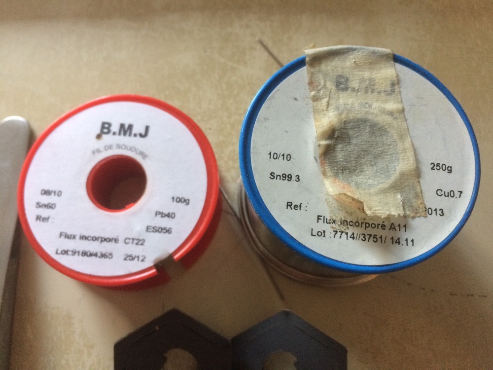
-I am about to order Pyralux to make this PCB a flexible part of my garment. I have a back-up plan to make flexible PCBs with a Copper shield I had bought last yearand Kapton Tape. I asked Camille to make some tests on it and it is very conductive because you can solder on it with common solder, and it is easily laser-cuttable and it is adhesive as well. I am thinking of interweaving that copper-layer with my modular-leather-garments to embed the circuit in it. But Pyralux might really be the right option.