FABRICADEMY FINAL PROJECT OUTCOMES

This Final Project is a PoC (Proof of Concept). It contains my Researches in HCI and Design during Fabricademy which it will overtake in Time and Space. Everything here will be carefully detailed to publish the contents of this research as a scientific publication rather than to offer a new product on the market of Fashion. Don't expect to see a working product. Instead, you will see a series of experiments on modular parts that could be assembled together and reconfigured in many other ways.

To prove was:

1-Modular Reconfigurable Design can contribute to connect HCI and Fashion Design.
2-Available Technics and Materials in the Fablab can lead to the assembly of "Fablab Made"
electronic substrate in replacement of commercial ones.
3-Recycled materials can be used for research (leather).
4-Modularity between flexible and rigid 2D, 2.5D and 3D parts in elegant ways.
5-Pluggability of passive and active functions (light, temperature, etc).
FABRICADEMY FINAL PROJECT

1-SURFACE IO is process-oriented.
2-Any 2D or 3D object can be converted into a sensing-surface via the assembly of press-fit,
flexible, tiles-like, 2.5D modules.
3-Simple and complex electronic-systems designs can be embedded into press-fit 3D parts that
can be inserted on SURFACE IO.
4-SURFACE IO is a modular, flexible, and parametric frame that can be folded and deployed on
any surface to fill-in a wide range of functions.
5-Highly painful to assemble, SURFACE IO requires more investigation and technical support to
reach its promises.
6-Sensing systems in 2D or 3D can be added, removed, or replaced, so do the tiles. Degrees of
freedom are therefore virtually unlimited.
7-SURFACE IO has a temperature sensor embedded in its structure that sends DATA to a computer.
8-Designed parametrically, the number of modules can vary infinitely according to the scale of
the object that needs to be sensed or that will be used as a substrate to sense the
environment that is around it.
9-SURFACE IO could cover a bridge, a tower, a dog, a human, or microthings and nanothings if
machined and assembled on a micro or a nanoscale.
10-And it could even go to space.
Files to download
Dispatched in assignment’s pages
extra picture
Design of artwork based on plant pattern. Modules and Connectors for a Modular-Reconfigurable Leather Garment
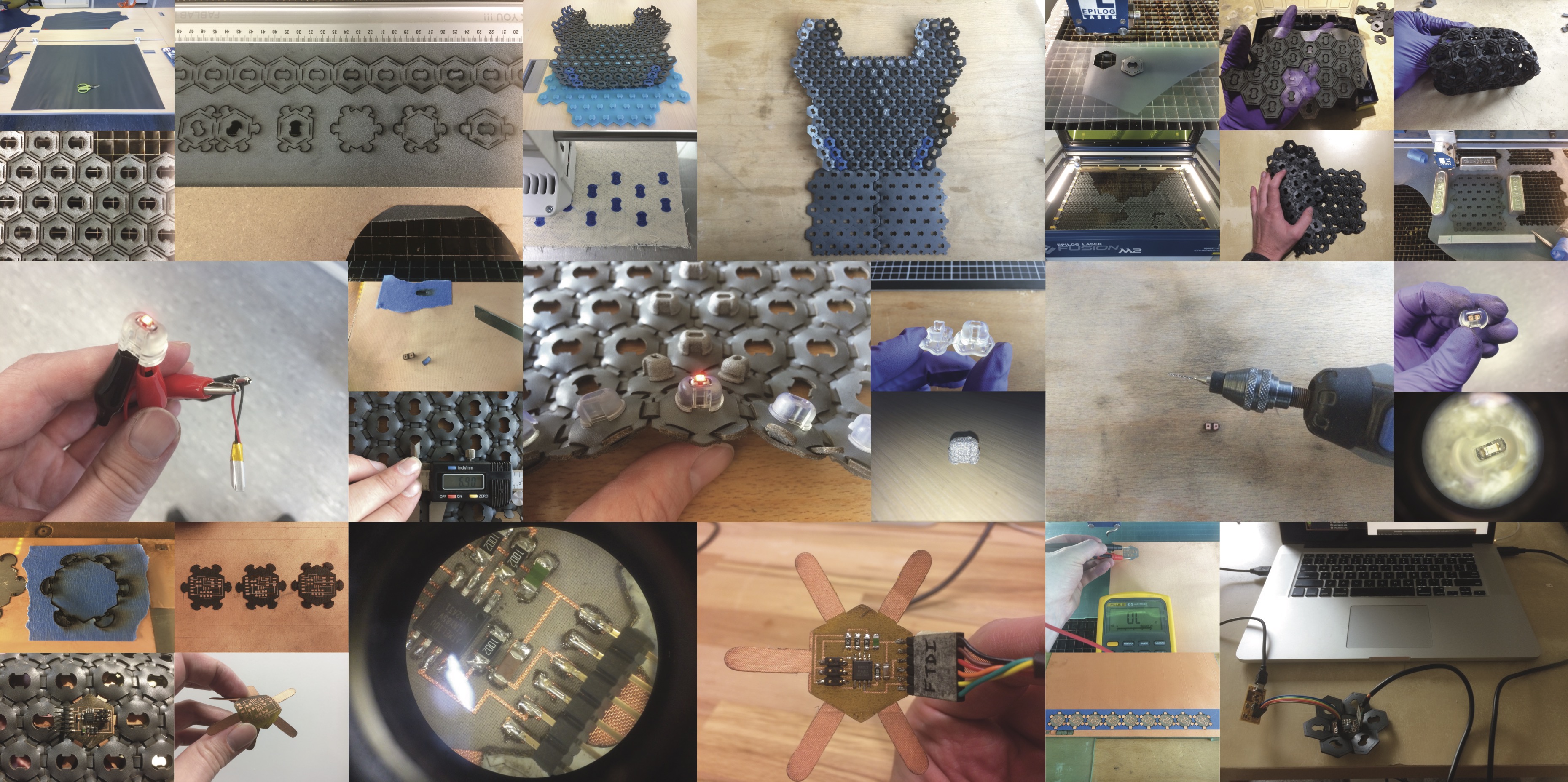
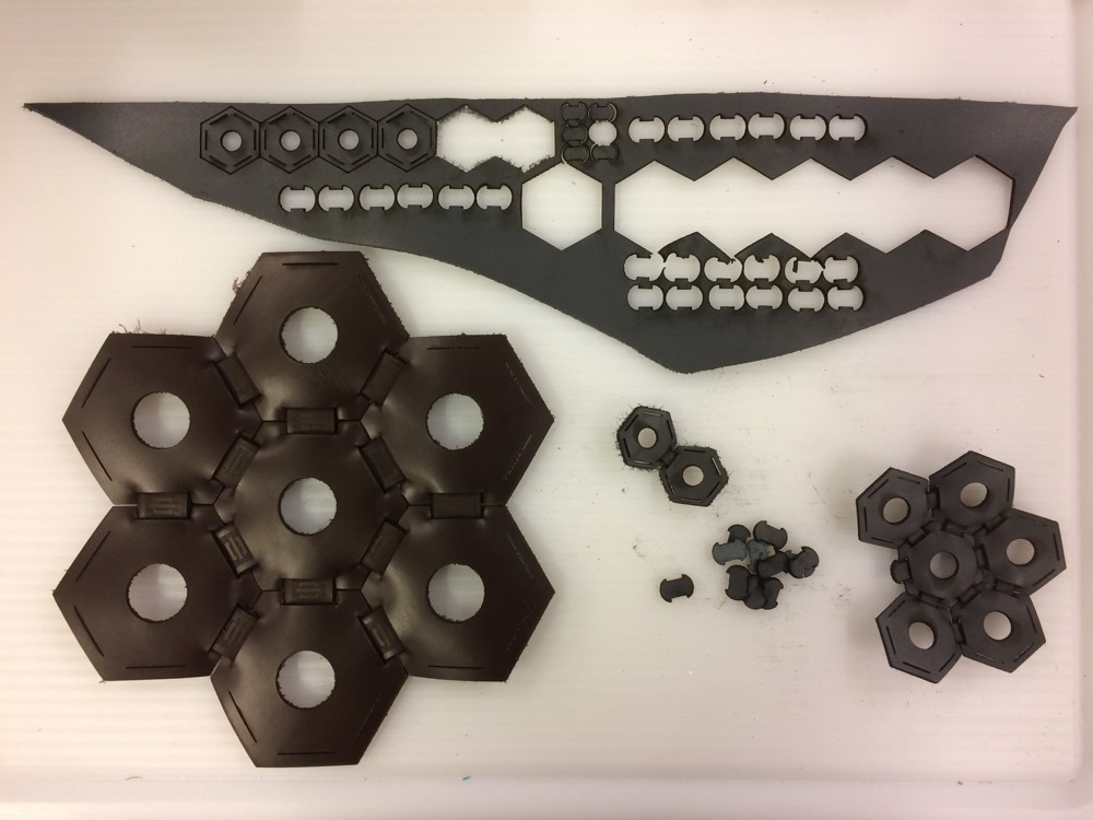
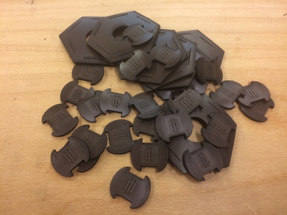
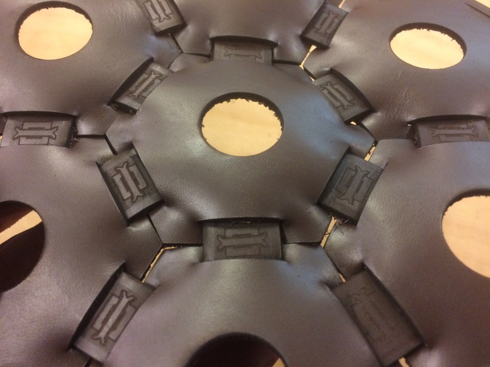
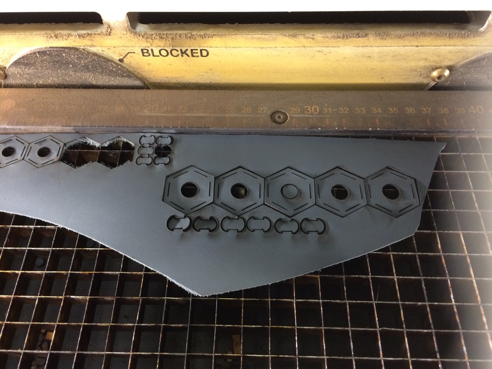
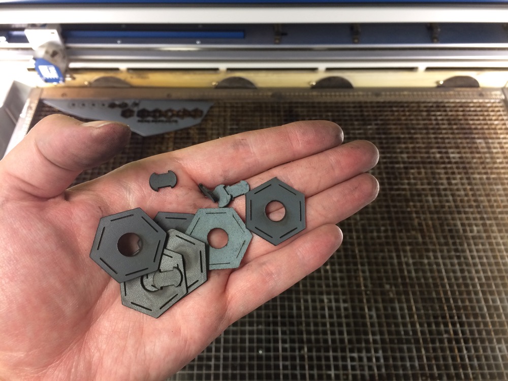
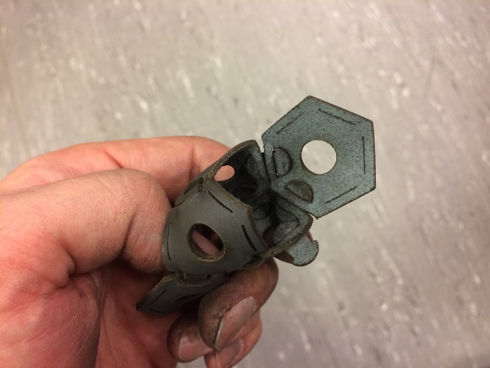
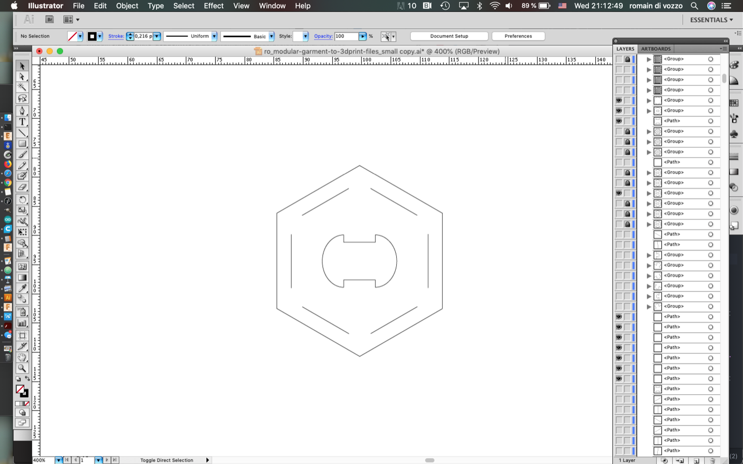
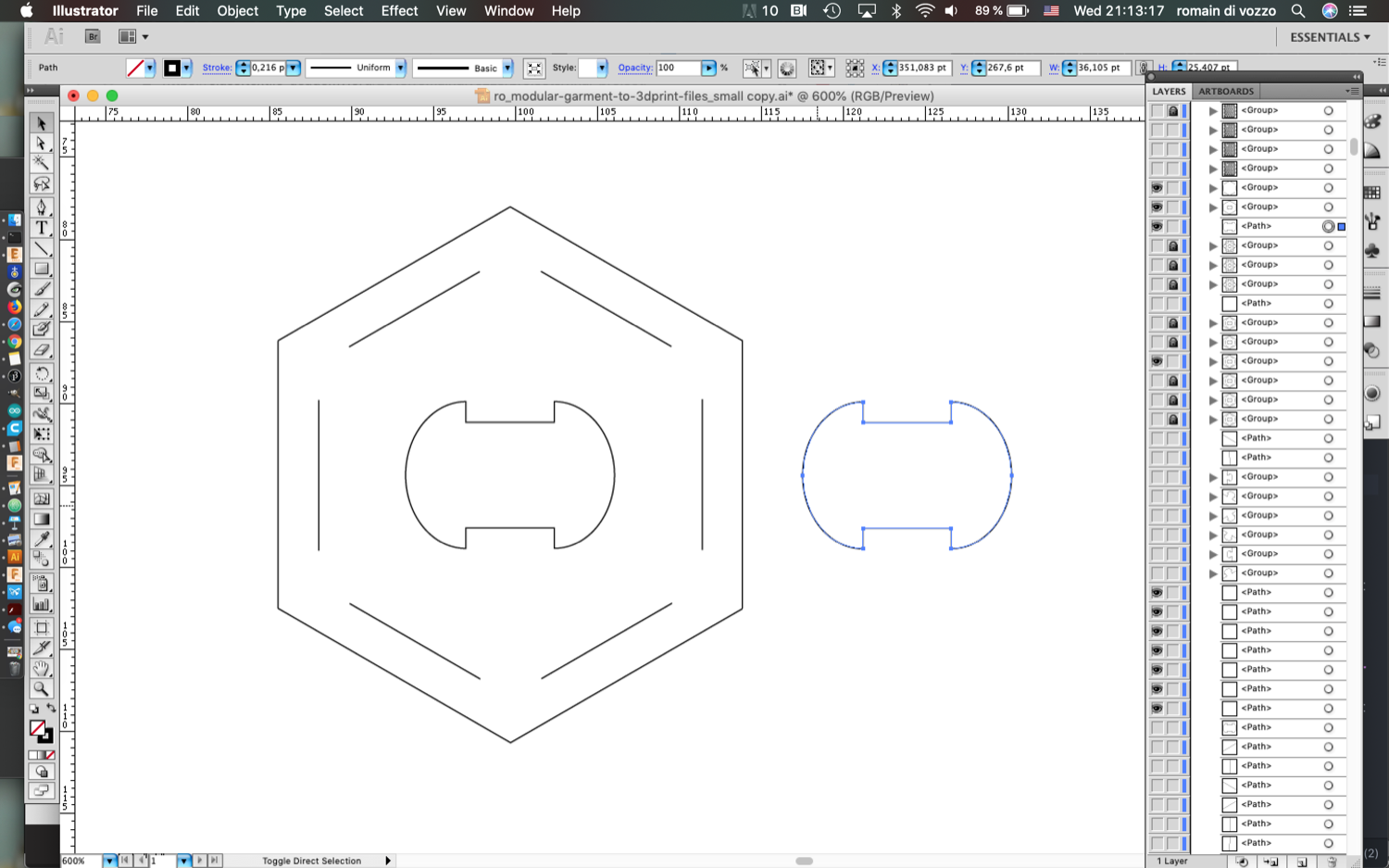
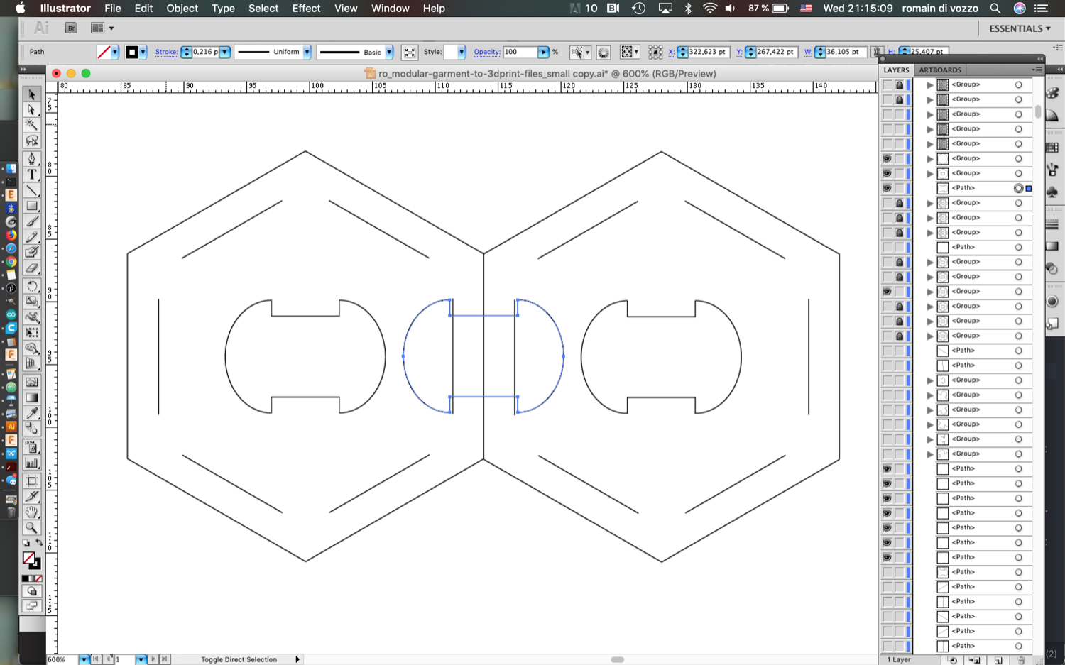
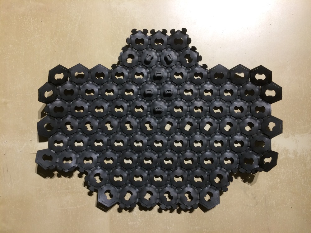
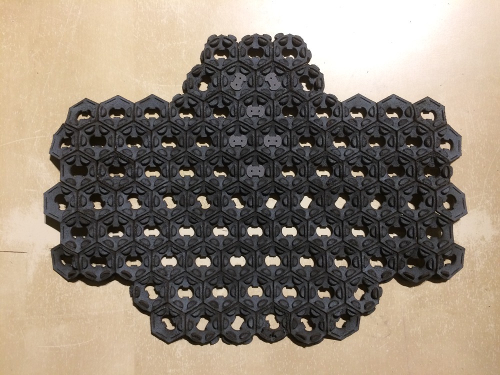
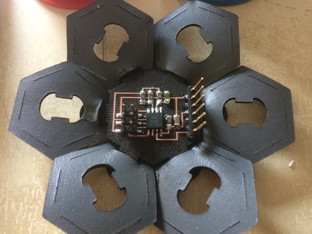
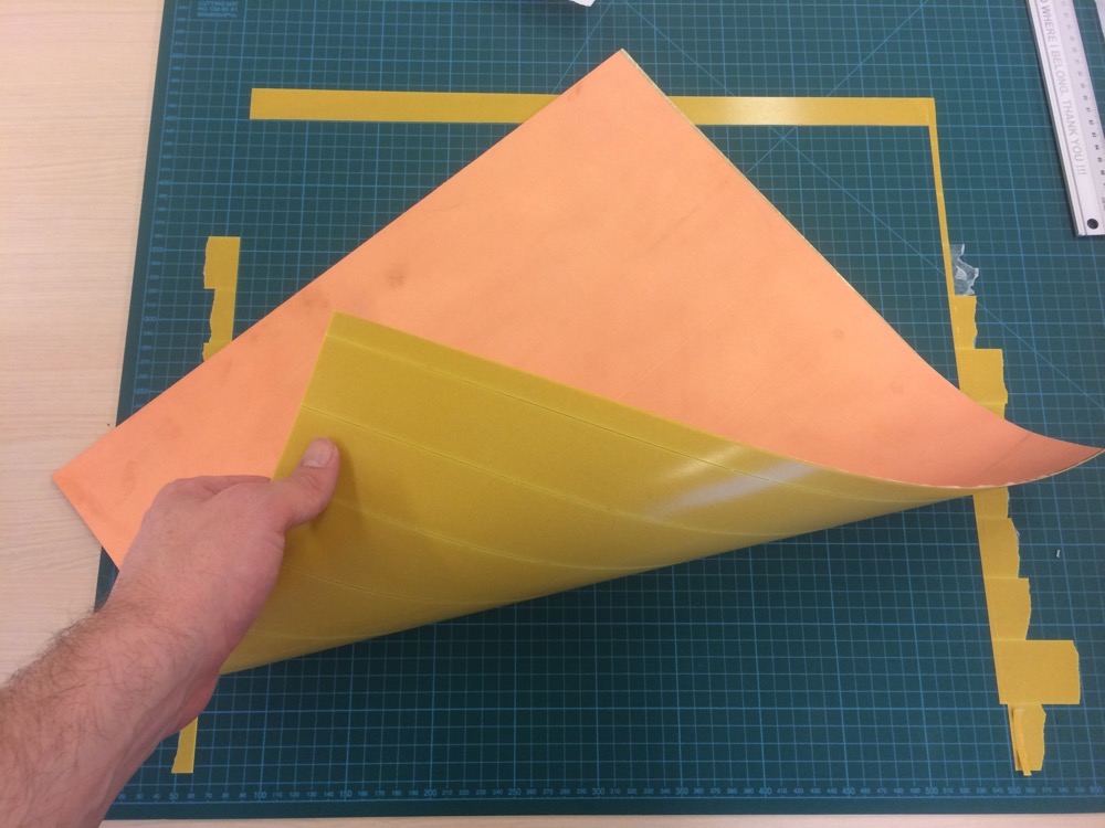
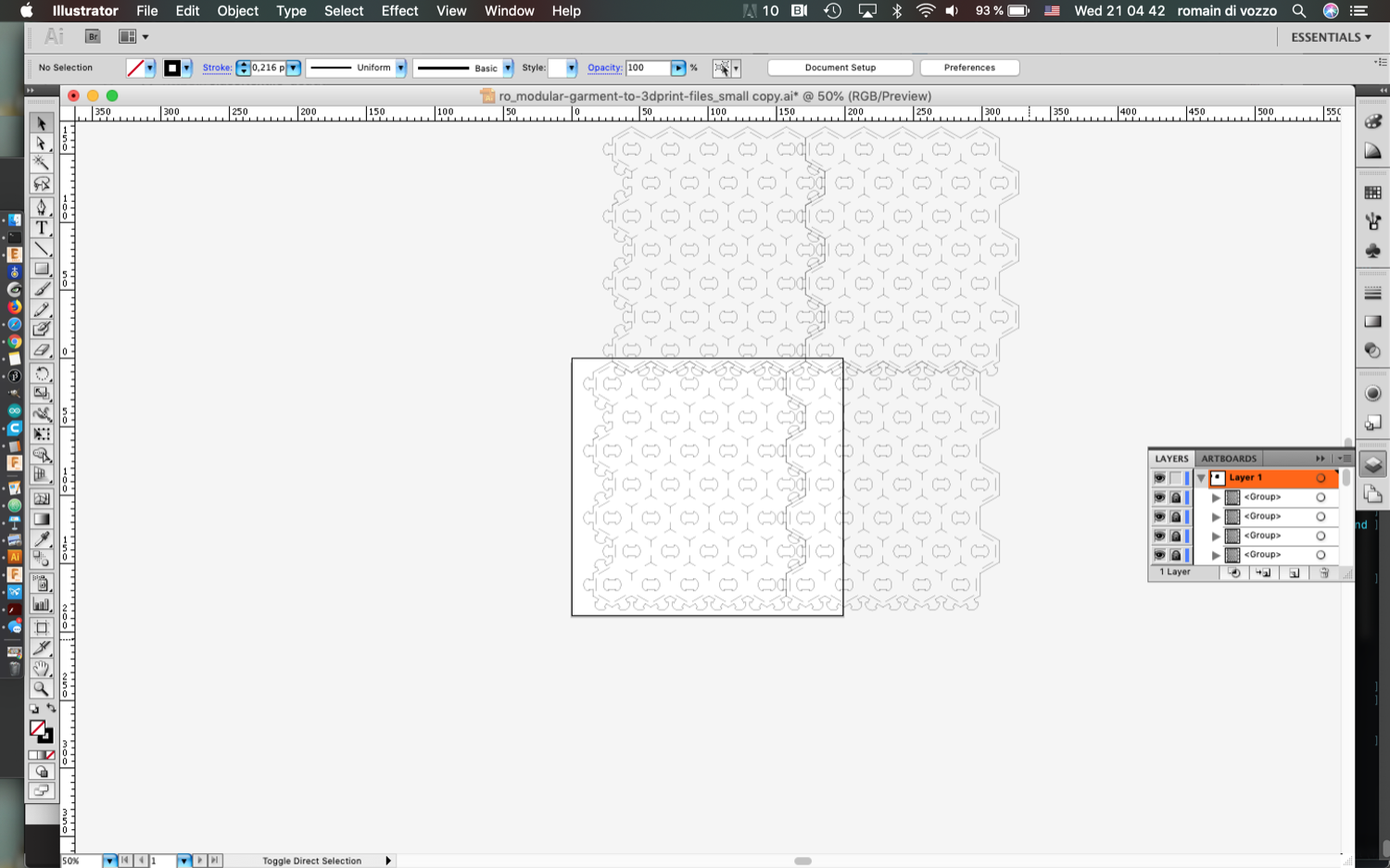
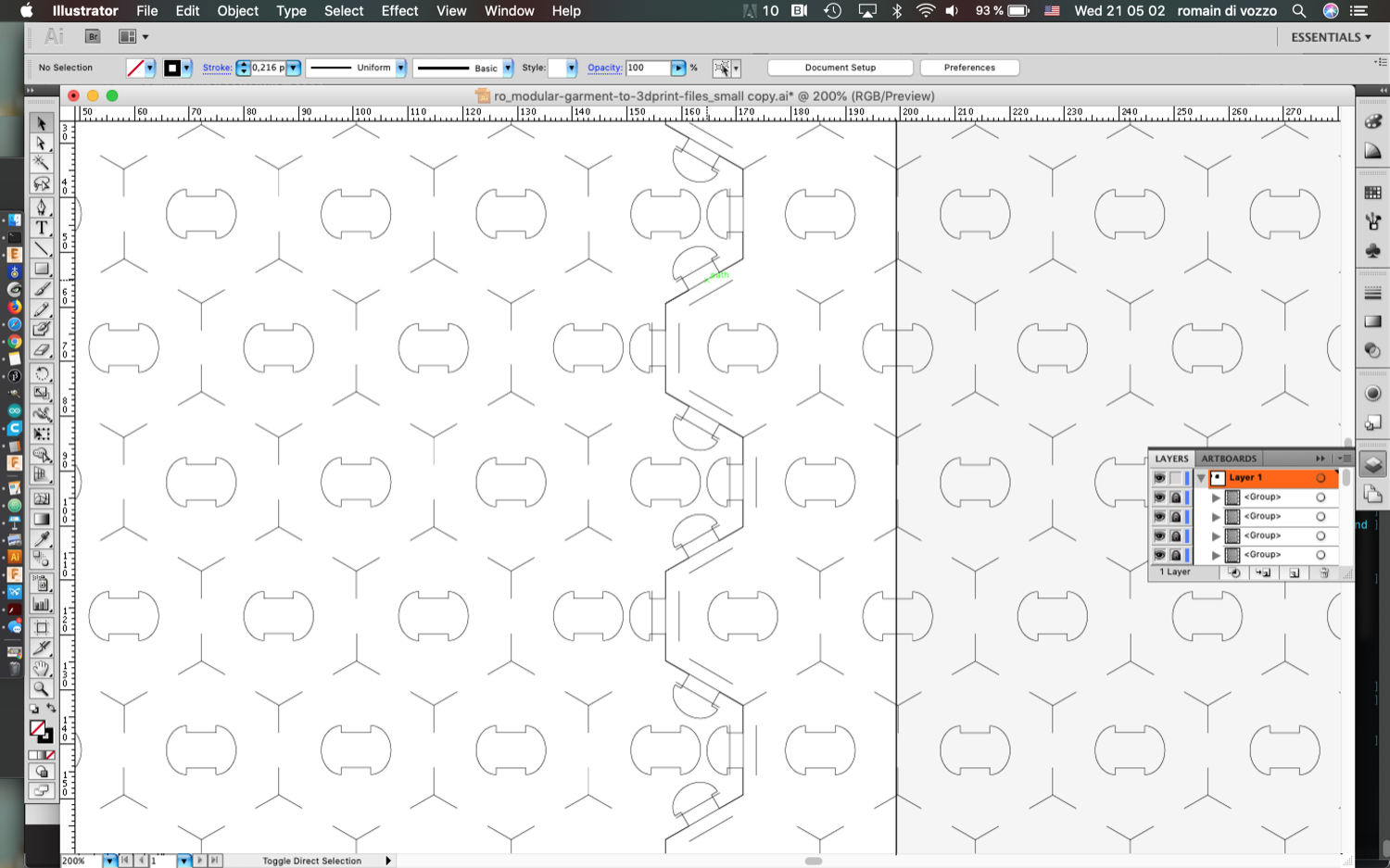
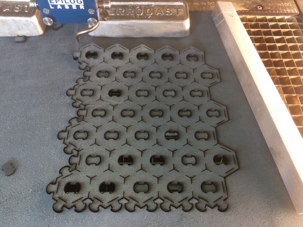
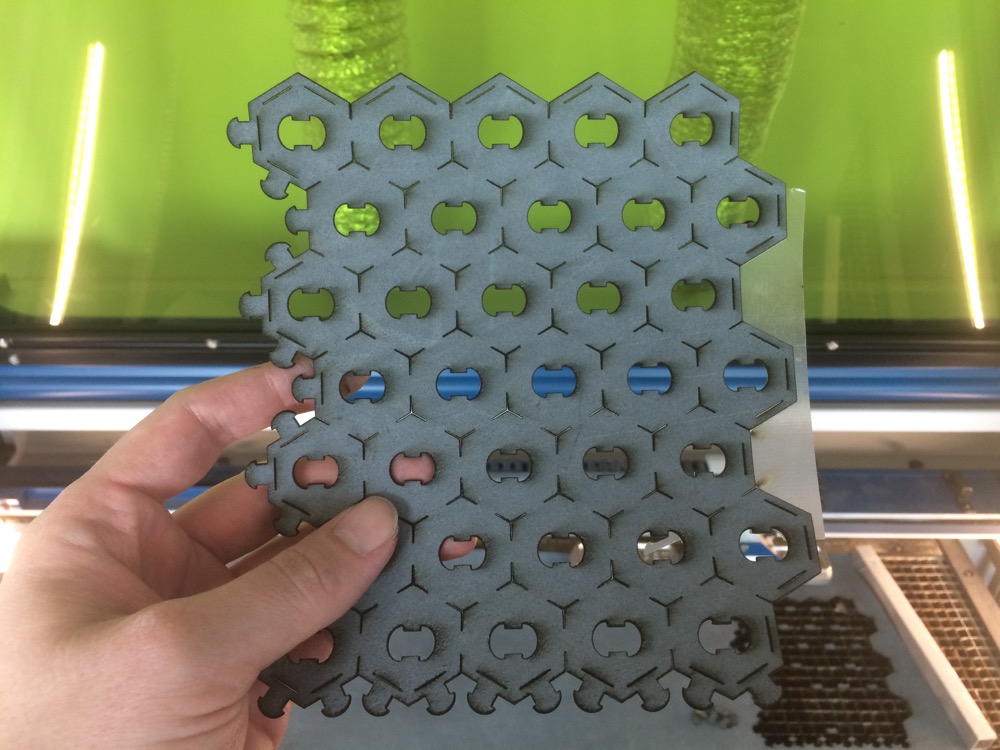
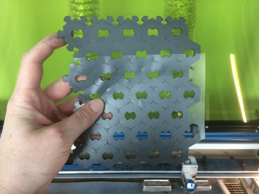
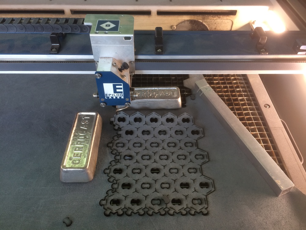
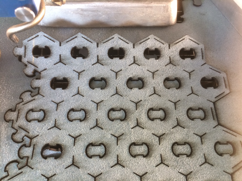
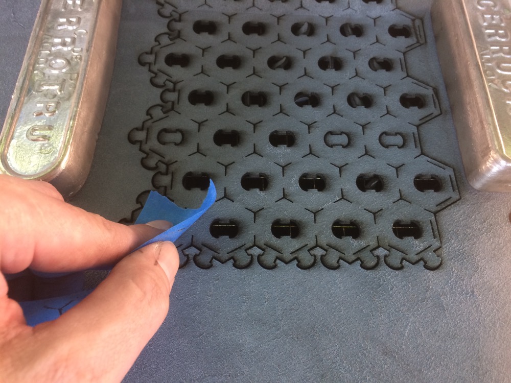
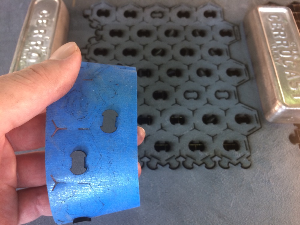
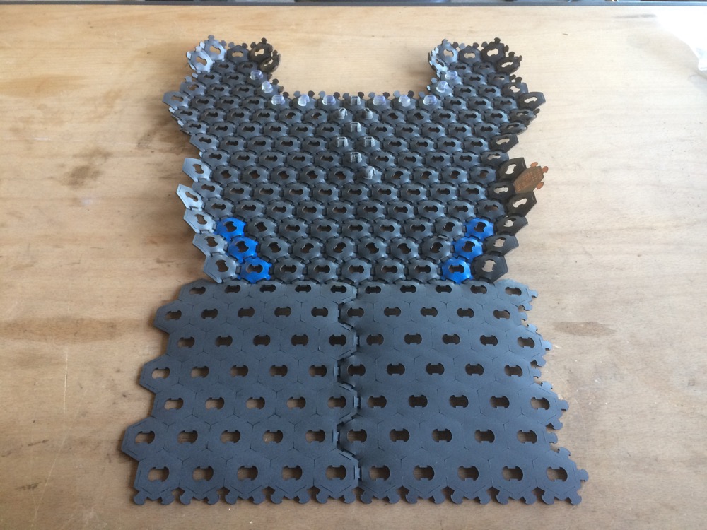
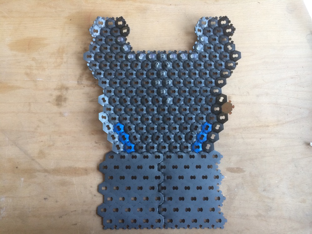
1/I have grounded my (main) final-project option to the modular-reconfigurable leather-garment I made for WEEK3. This garment is made of laser-cut leather hexagonal modules of 30mm x 30mm x 1.7mm (thickness).
1.1
Design and Scale-Modulation of Hexagonal Modules and Connectors for a Modular-Reconfigurable Leather Garment
1.2
Laser-cut Tests and Assembly of Hexagonal Modules and Connectors for a Modular-Reconfigurable Leather Garment
1.3
1.4
Hexagonal Modules and Connectors Big Format
Hexagonal Modules and Connectors Big Format Assembled
1.5
1.6
Hexagonal Modules and Connectors Smaller Format
Hexagonal Modules and Connectors Smaller Format
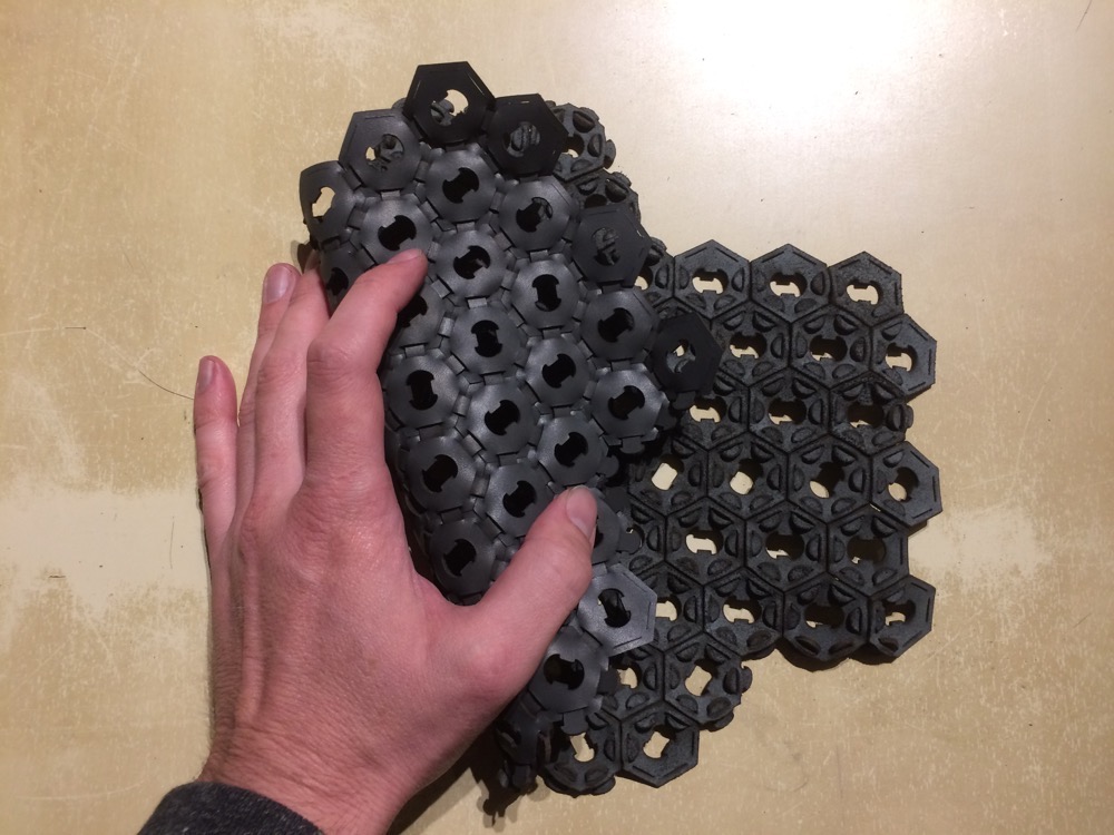
2/At the very beginning, the idea was to simply assemble those modules via the connectors to cover small or big surfaces - non-humans and humans surfaces. While assembling the modules and the press-fit connectors (painfully), I realised how close the Third Dimension was by folding the connected modules on themselves. I was leaving 2.5D to go 3D through foldable-reconfigurable patterns.
2.1
2.2
Folding 2.5D Garment into a 3D Object
Folding 2.5D Garment into a 3D Object
ADD PICTURE
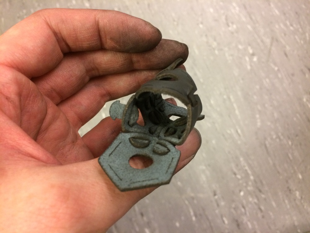
3/In the middle of each 30mm x 30mm hexagonal leather module, I cut self-blocking leather press-fit connectors to serve as connectors between the hexagonal modules and to keep them tight together. This way I could optimize the leather stock I have by UpCycling parts of the cut.
3.1
3.2
3.3
blablabla
blablabla
blablabla
3.4
bababla
3.5
bababla
3.6
bababla
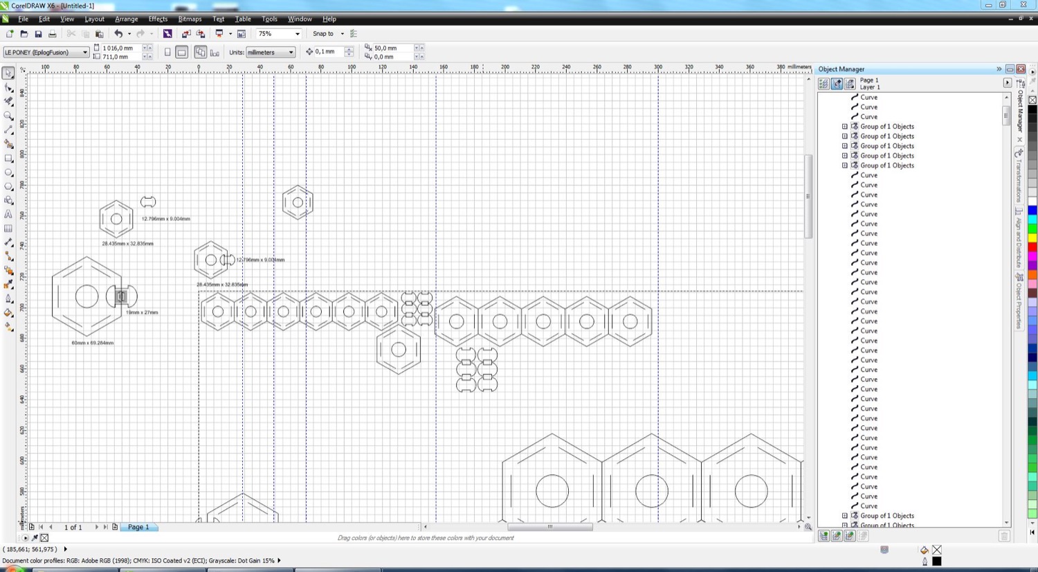
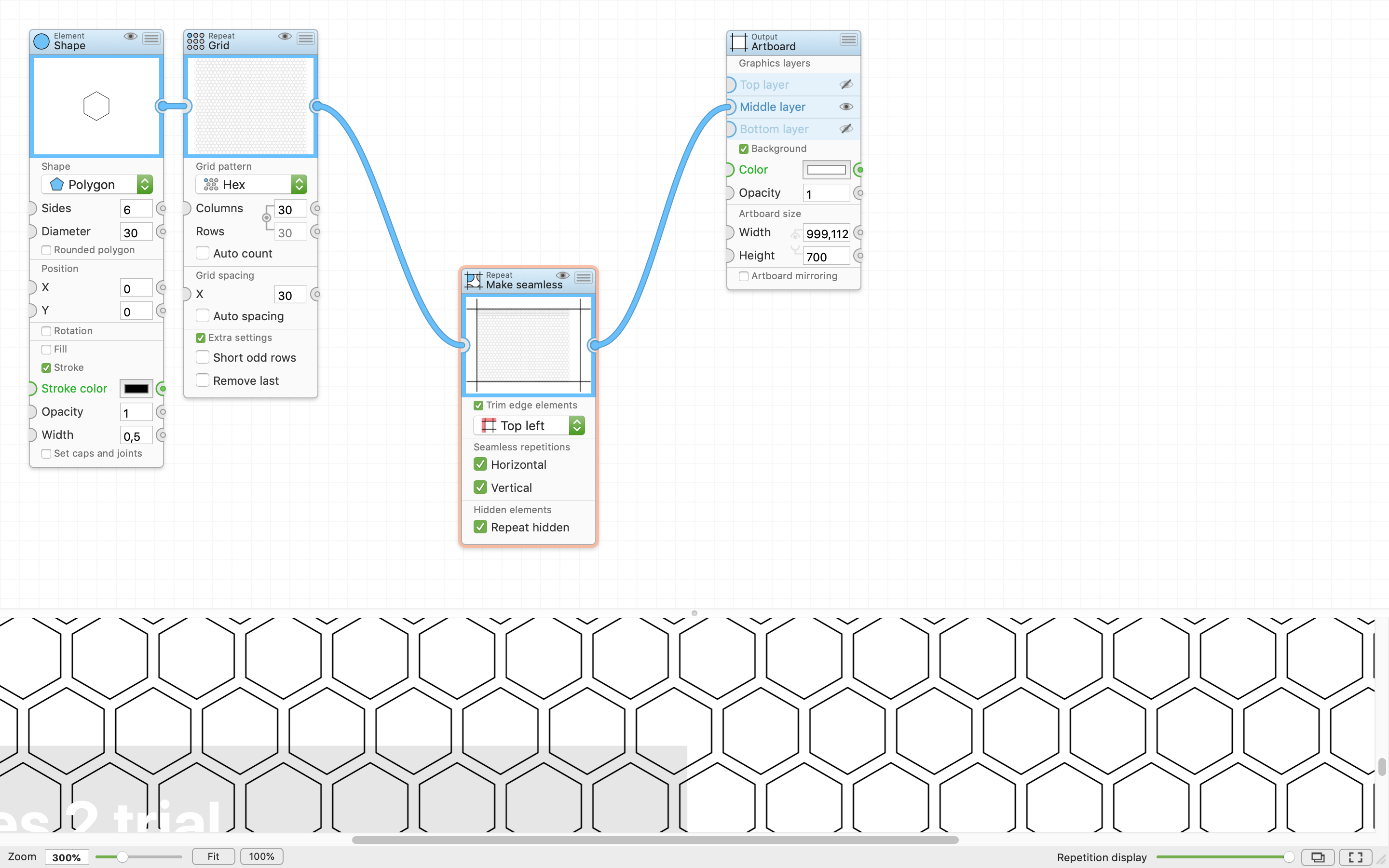
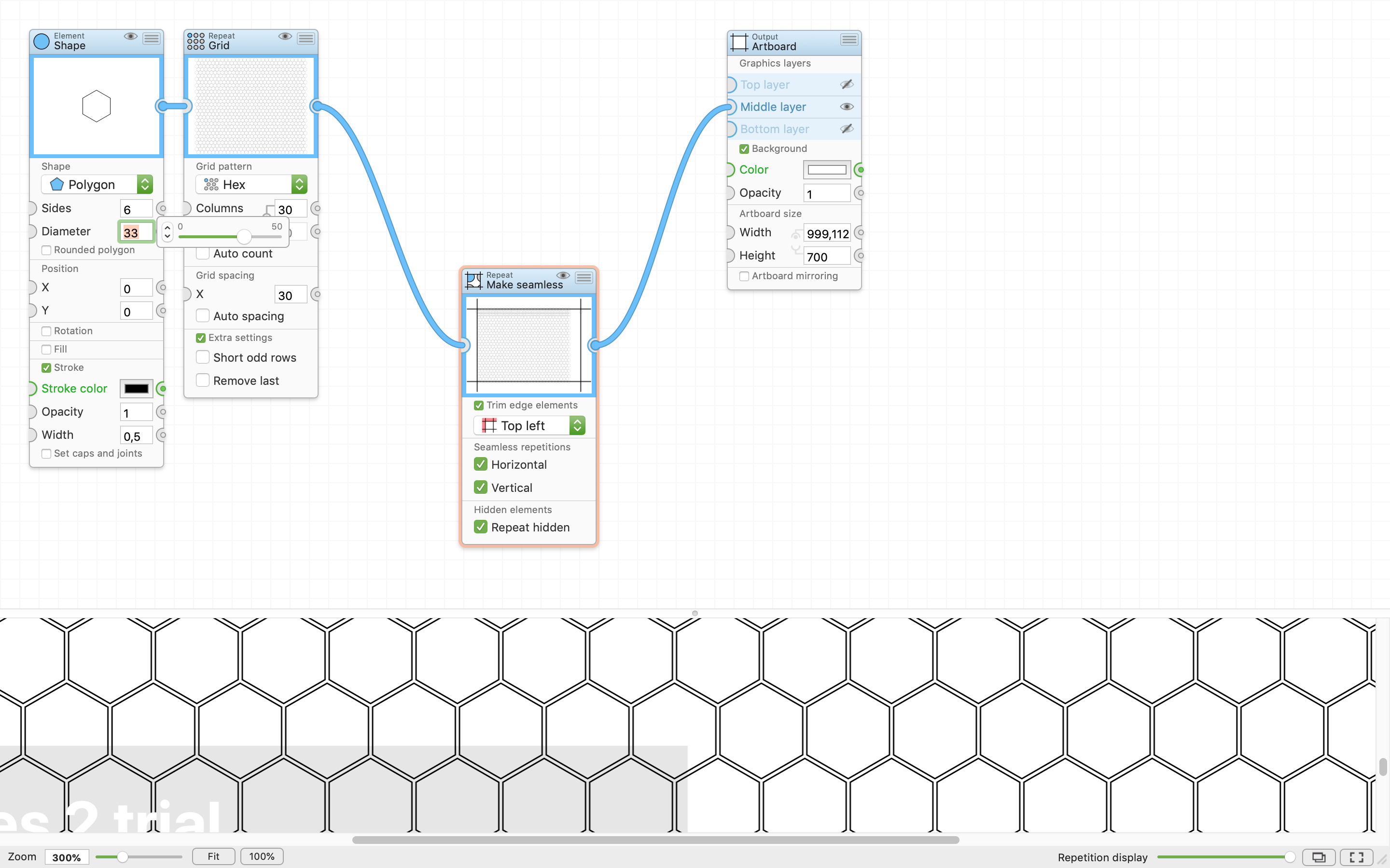
At the very end of this project I started to think that the design of those patterns would deserve to be automatized. I don’t code apps but I’d be happy to learn how to code in Java if I had a good reason. Even Processing might help in doing so. Time is lacking for now, but I found apps on line.
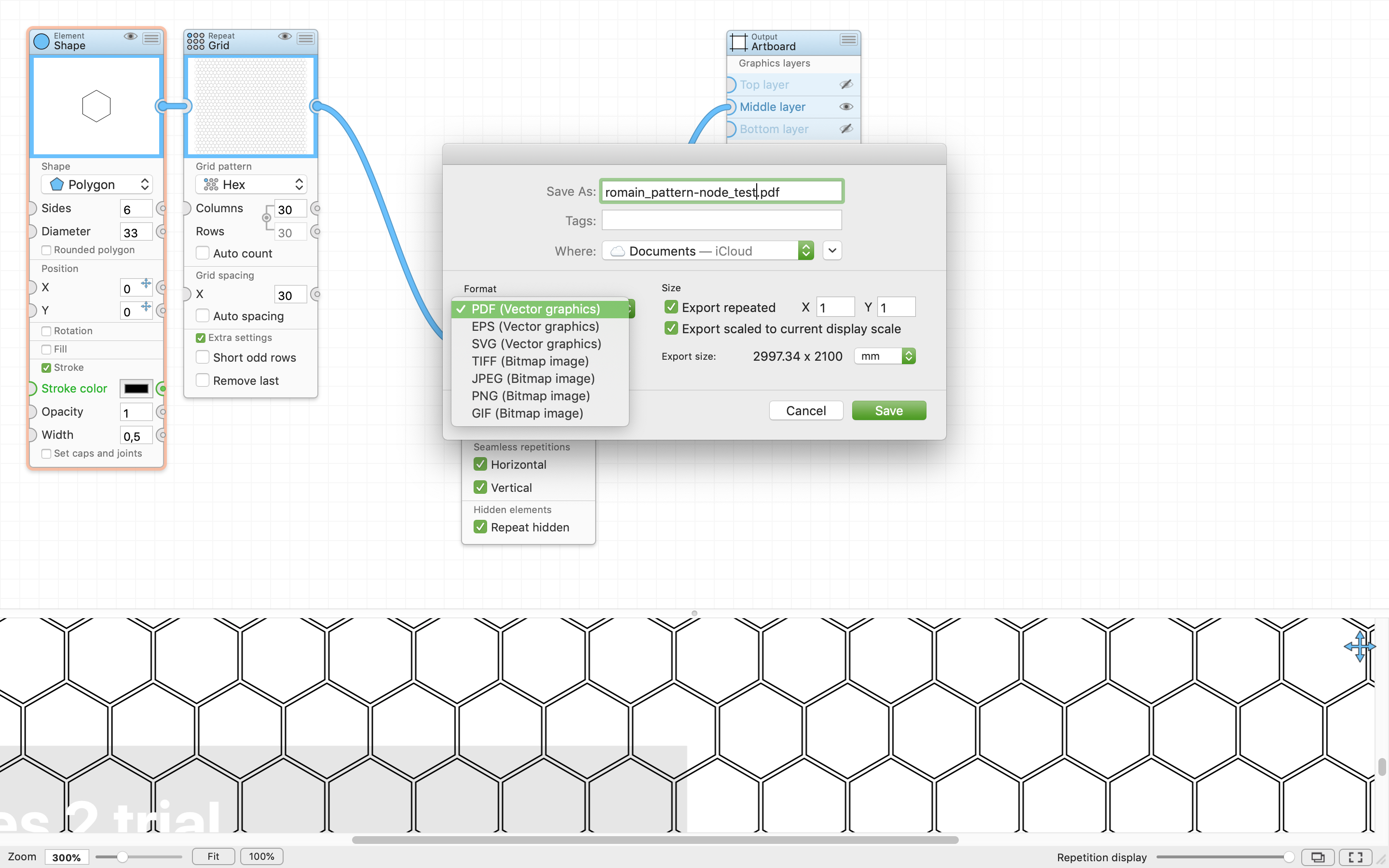
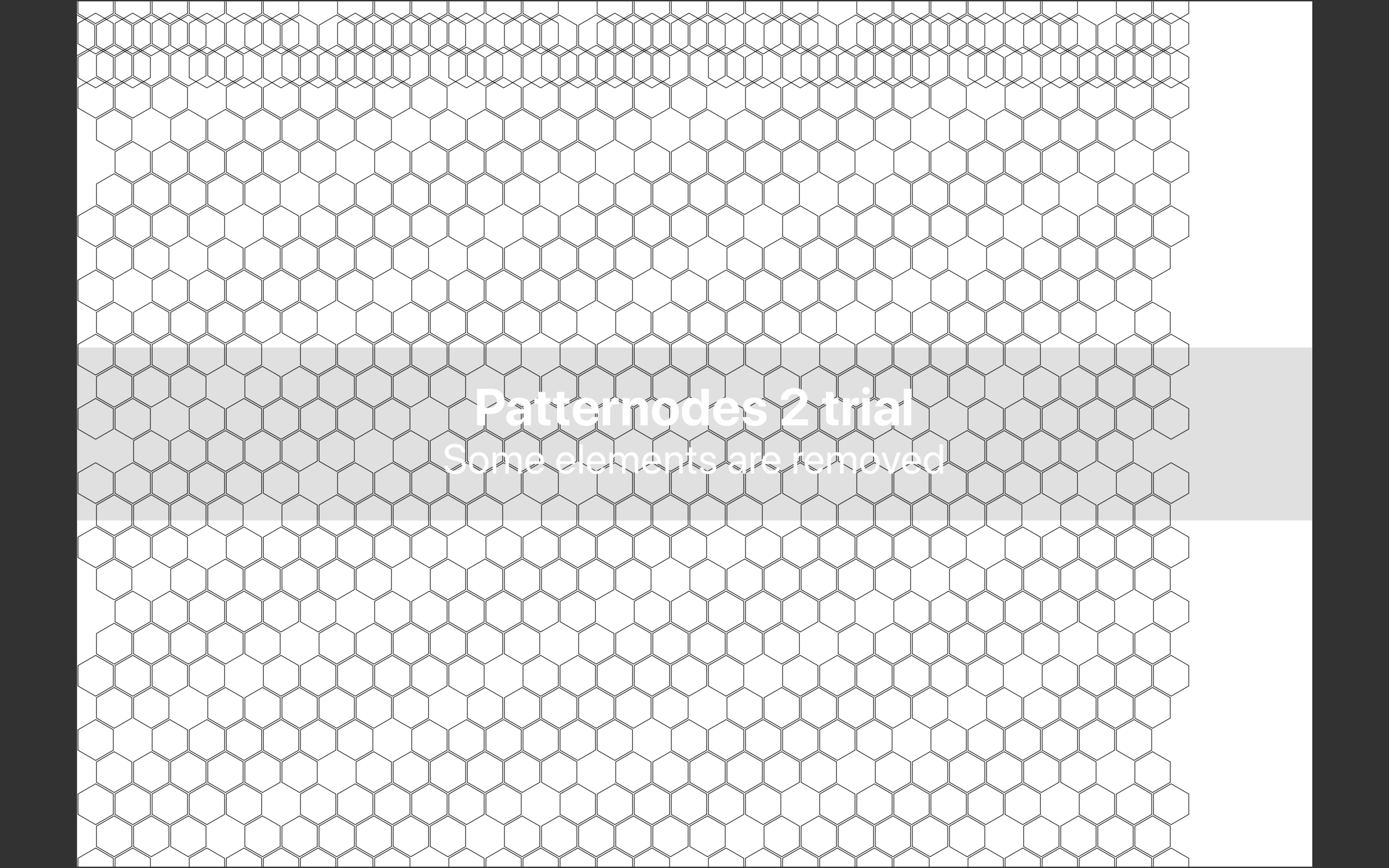
Patternodes looks like MODS. Nice interface. Output is far from being perfect as you can see. I hope it is just a Trial Mode issue.
3.7
3.8
3.9
3.10
Patternodes Interface
Patternodes Interface
Patternodes Export
Patternodes Output
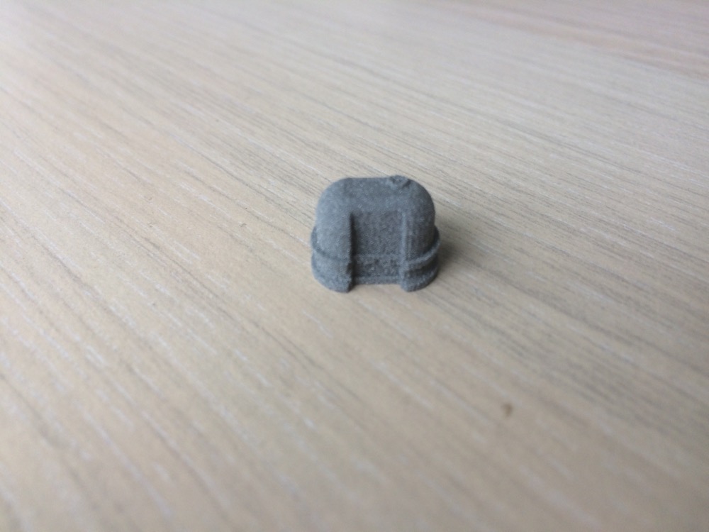
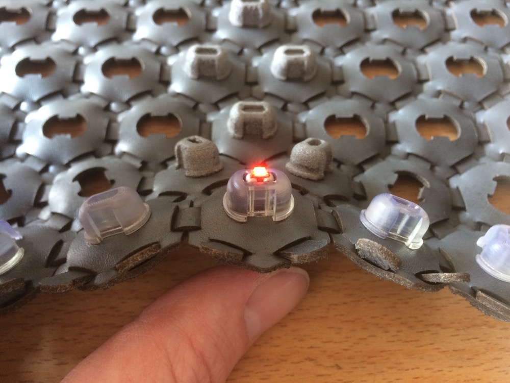
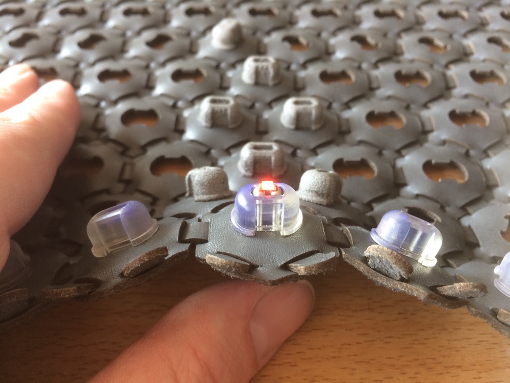
4/Observing the garment folding and reaching the third dimension between my hands had side-effects. The holes left by the laser-cutter after cutting the press-fit connectors out of the hexagons appeared as a space left to be define with a function. This is when I designed a pluggable-press-fit 3D module from the constraints offered by the edges of the laser-cut holes left in the leather. The garment was then augmented by a 3D press-fit connector, that I would right away 3D print with a passive-reflective plastic. The discret intermittent-light function was added.
ADD SCREENSHOT OF 3D Modeling
4.1
4.2
4.3
3D Printed Press-fit Connector
3D Printed Press-fit Connector
3D Printed Press-fit Connector Reflecting Light Passively
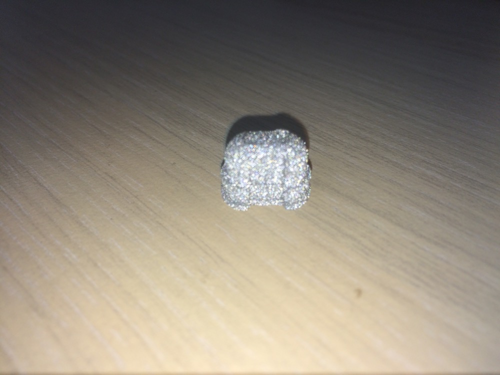
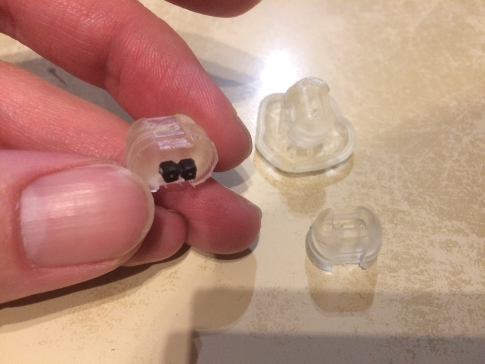
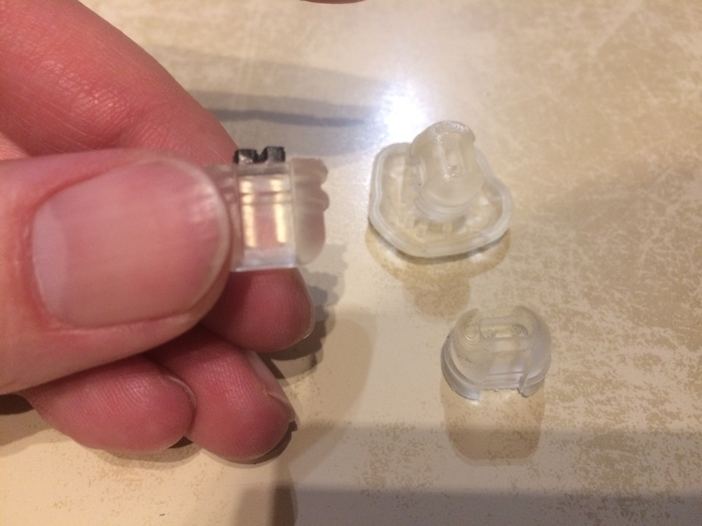
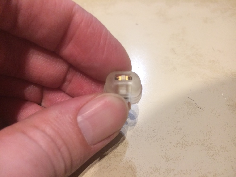
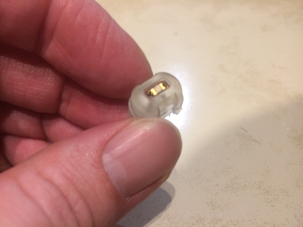
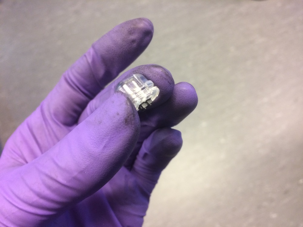
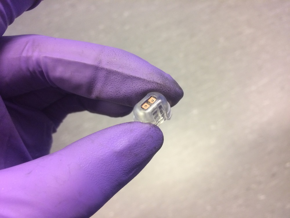
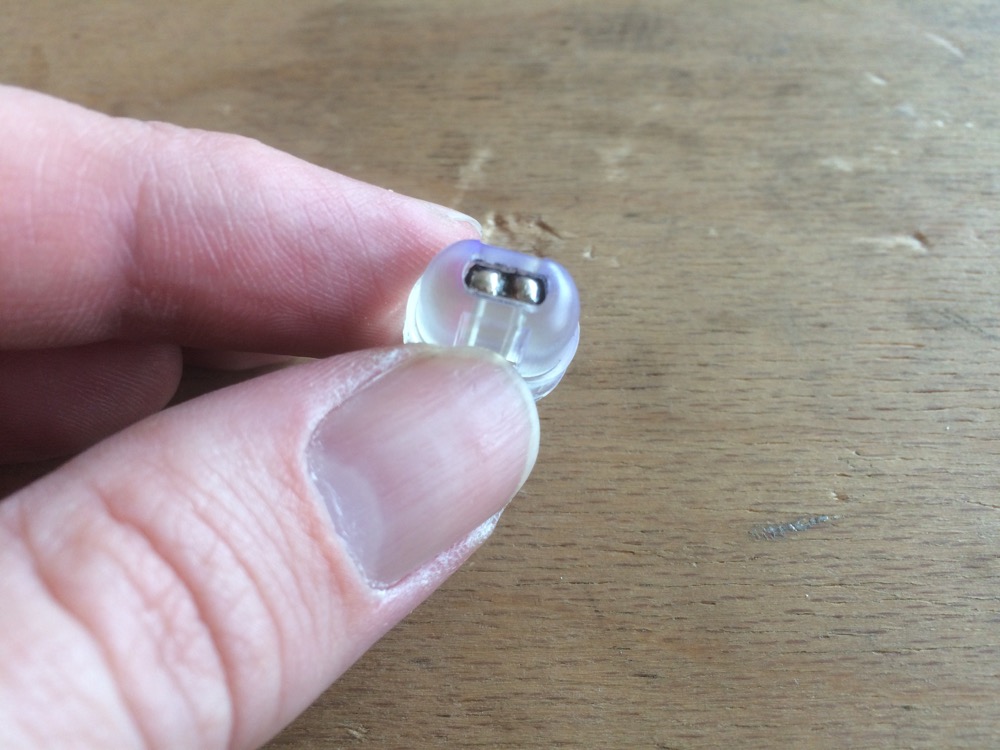
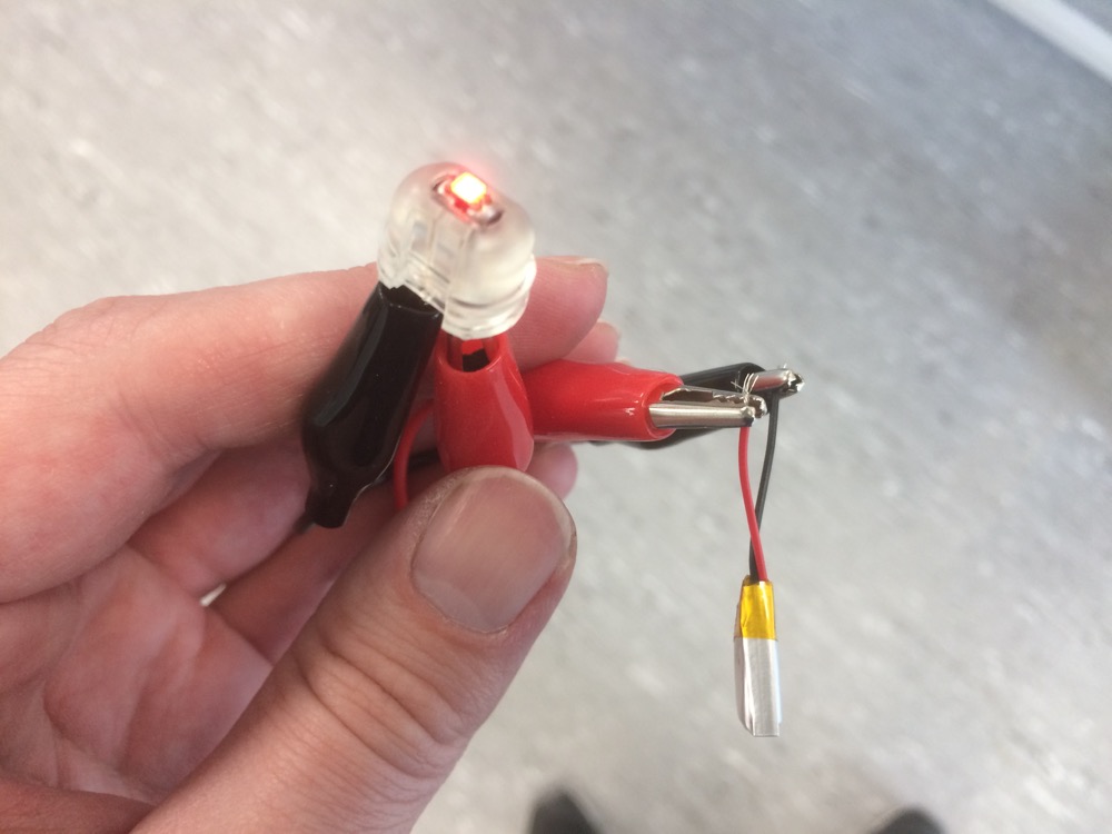
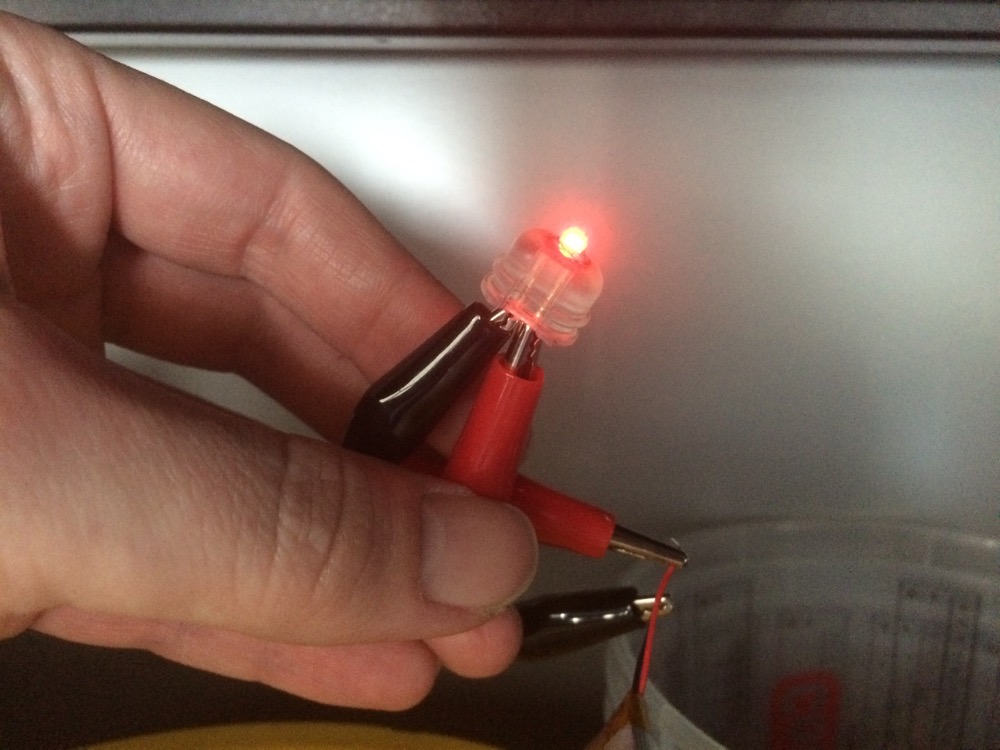
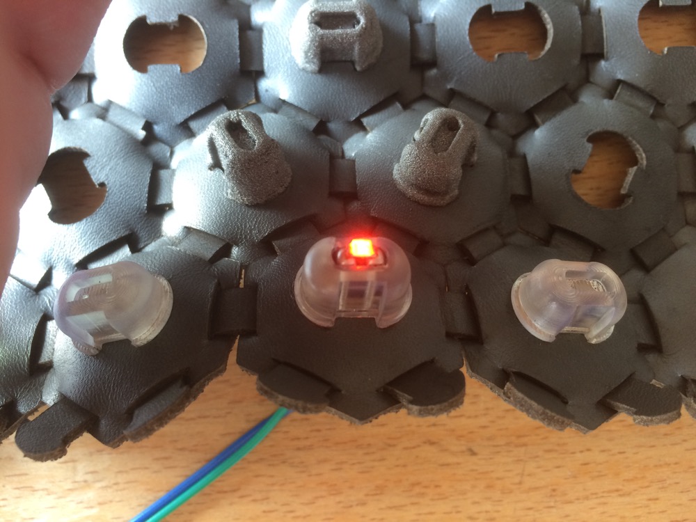
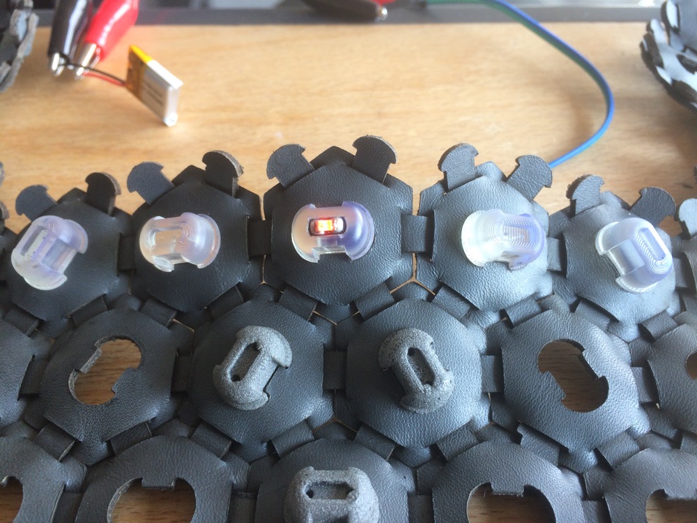
5/While designing the 3D press-fit connectors I optionally added two cylindrical holes and a rectangular pocket to add continuous light emission. The holes were added again to embed 1206 LEDs to a translucent 3D printed version of the 3D press-fit connector.
5.1
5.2
5.3
3D Printed Press-fit Connector
3D Printed Press-fit Connector
3D Printed Press-fit Connector Reflecting Light Passively
5.4
5.5
5.6
3D Printed Press-fit Connector
3D Printed Press-fit Connector
3D Printed Press-fit Connector Reflecting Light Passively
5.7
5.8
3D Printed Press-fit Connector
3D Printed Press-fit Connector
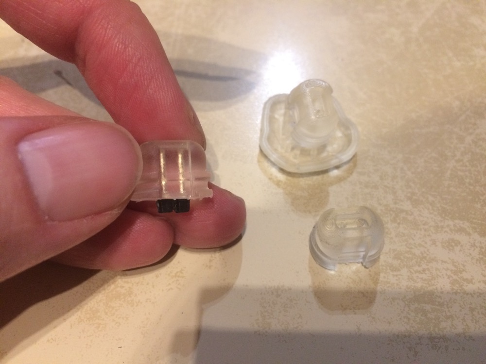
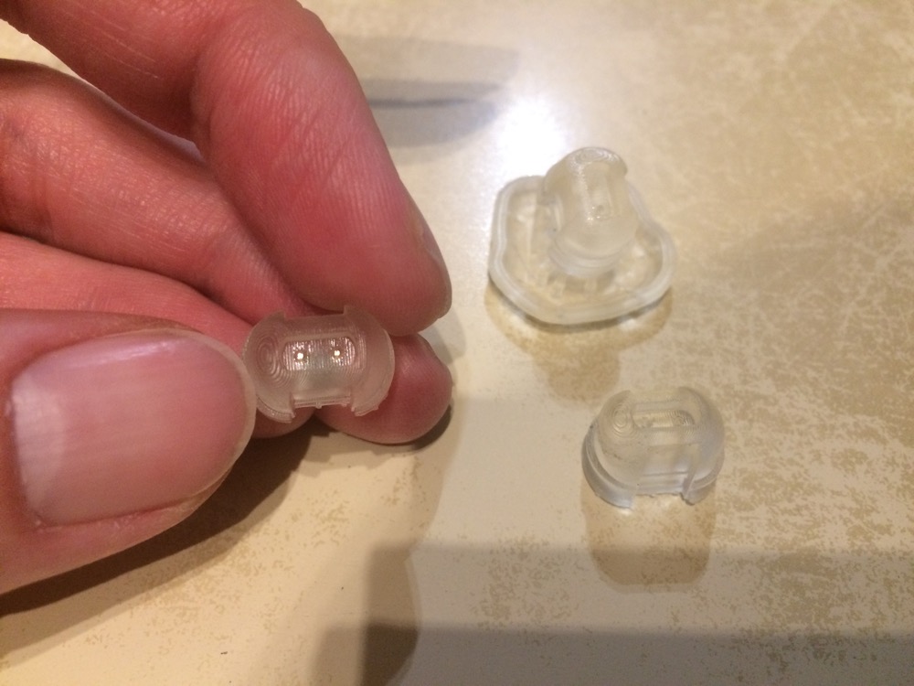
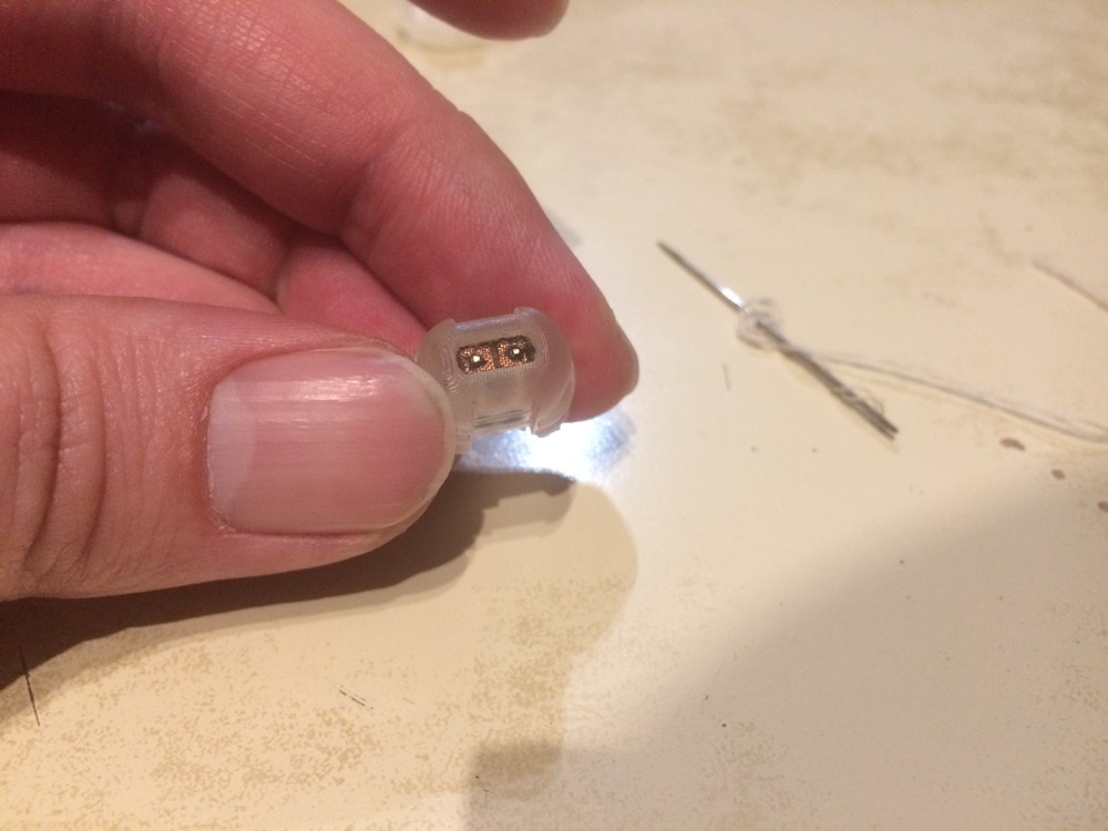
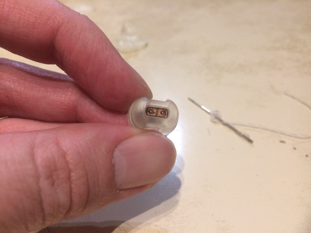
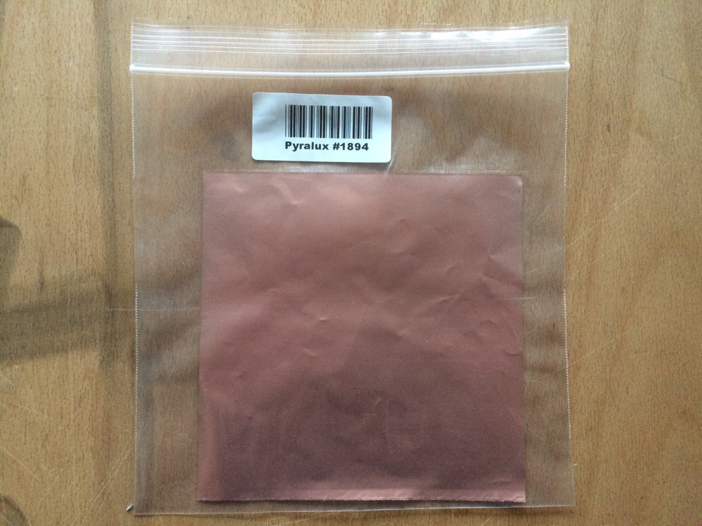
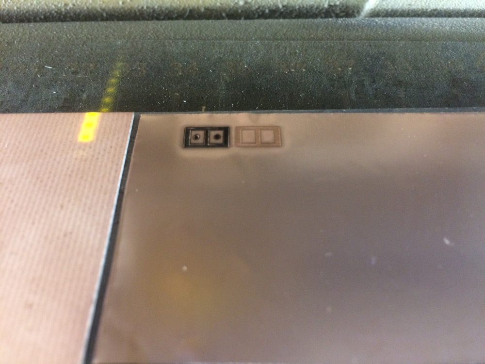
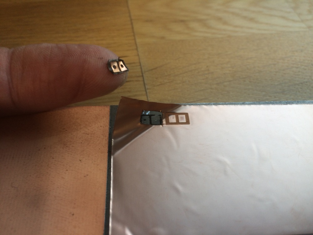
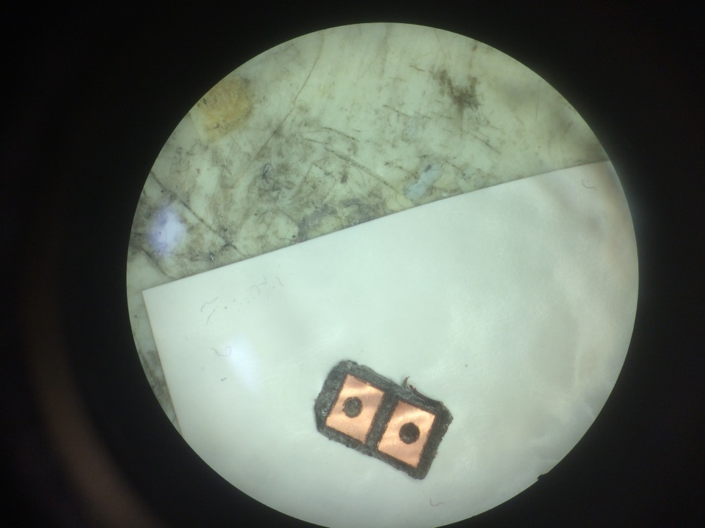
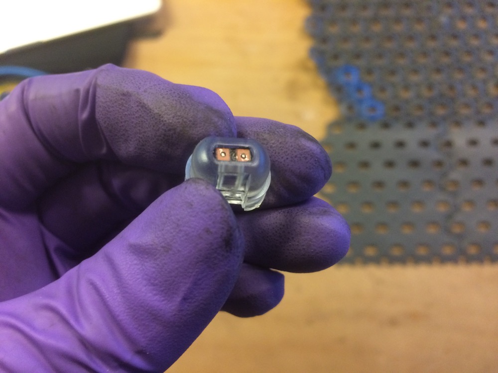
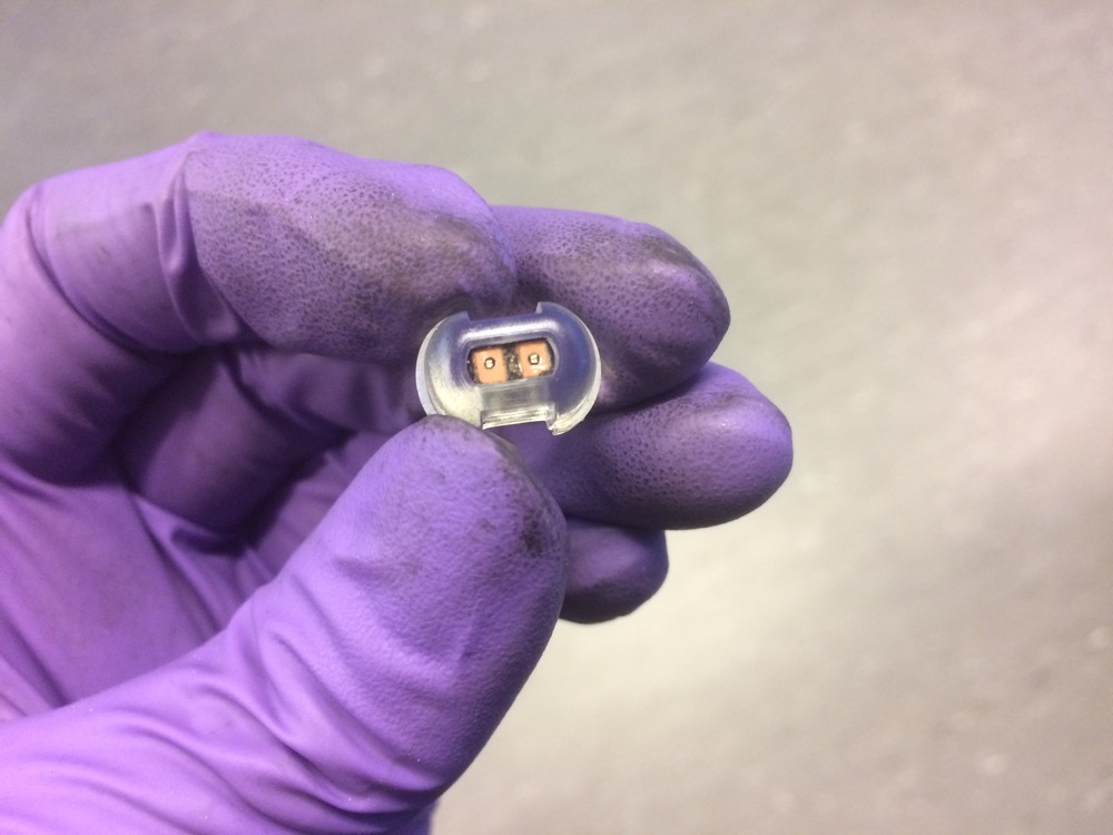
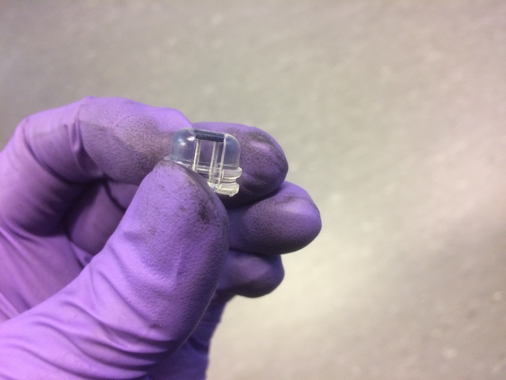
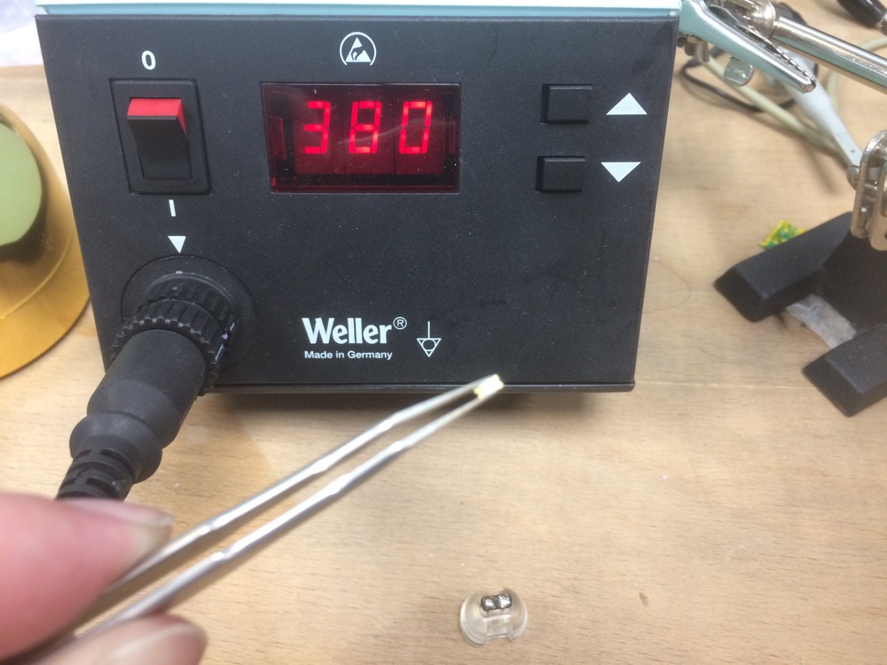
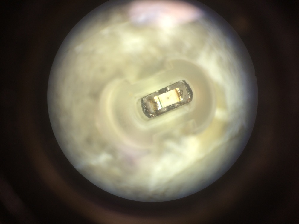
I finally got the time to design a small 2-pads PCB as well as to find longer pins to plug inside de connector and to solder a 1206 LED on top of it. The design is tricky to solder because of its size but mostly because it has to be rethought. For the POC, I am ok to leave it like that for now.
Add pix of cad design here
I first tried to cut it out of the Pyralux we finally received from Mouser.
5.9
5.10
3D Printed Press-fit Connector
3D Printed Press-fit Connector
5.11
5.12
3D Printed Press-fit Connector
3D Printed Press-fit Connector
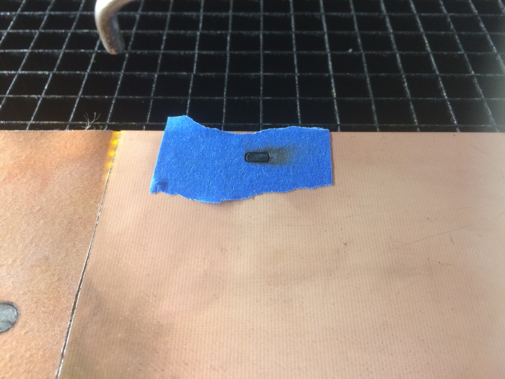
But as I needed rigidity to keep the PCB stable inside the 3D press-fit connector, I laser etched/cut the PCB out of a thinner FR4 - .8mm thick. I might be able to get better results by removing material from a thicker material than weakening a flexible one.
5.13
5.14
3D Printed Press-fit Connector
3D Printed Press-fit Connector
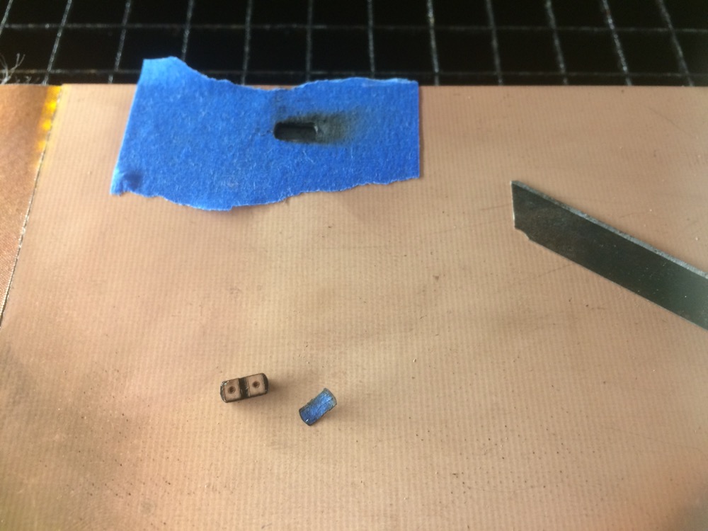
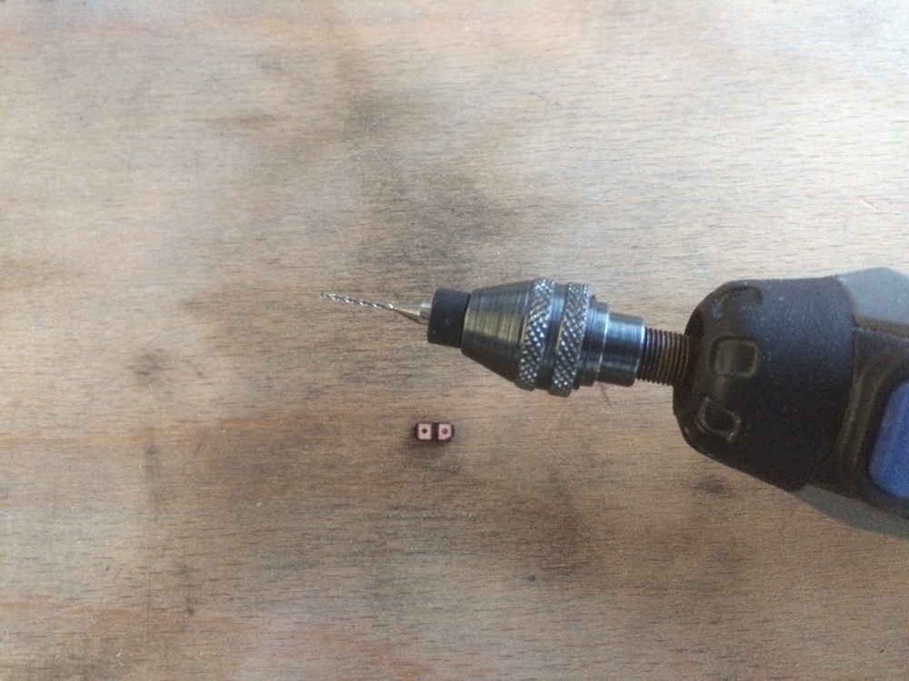
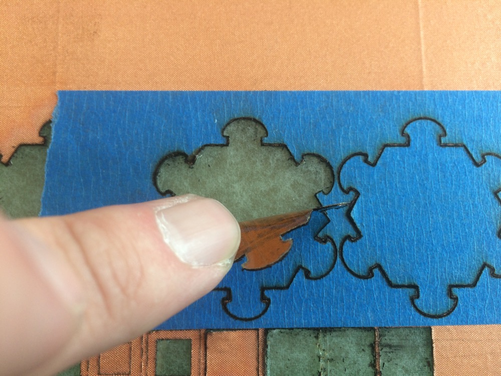
I had to drill the holes with a Dremel. Using the CO2 laser to go through this FR4 PCB on such a small surface - we are talking about Diameter 1mm holes - would burn the PCB after the 6 passes required to go through the material.
5.15
Manually drilling holes to avoid burns on the PCB
And everything fits perfectly
5.16
5.17
3D Printed Press-fit Connector
3D Printed Press-fit Connector
5.18
5.19
3D Printed Press-fit Connector
3D Printed Press-fit Connector
5.20
5.21
3D Printed Press-fit Connector
3D Printed Press-fit Connector
5.22
5.23
3D Printed Press-fit Connector
3D Printed Press-fit Connector
5.24
5.25
3D Printed Press-fit Connector
3D Printed Press-fit Connector
5.26
5.27
3D Printed Press-fit Connector
3D Printed Press-fit Connector
5.28
5.29
3D Printed Press-fit Connector
3D Printed Press-fit Connector
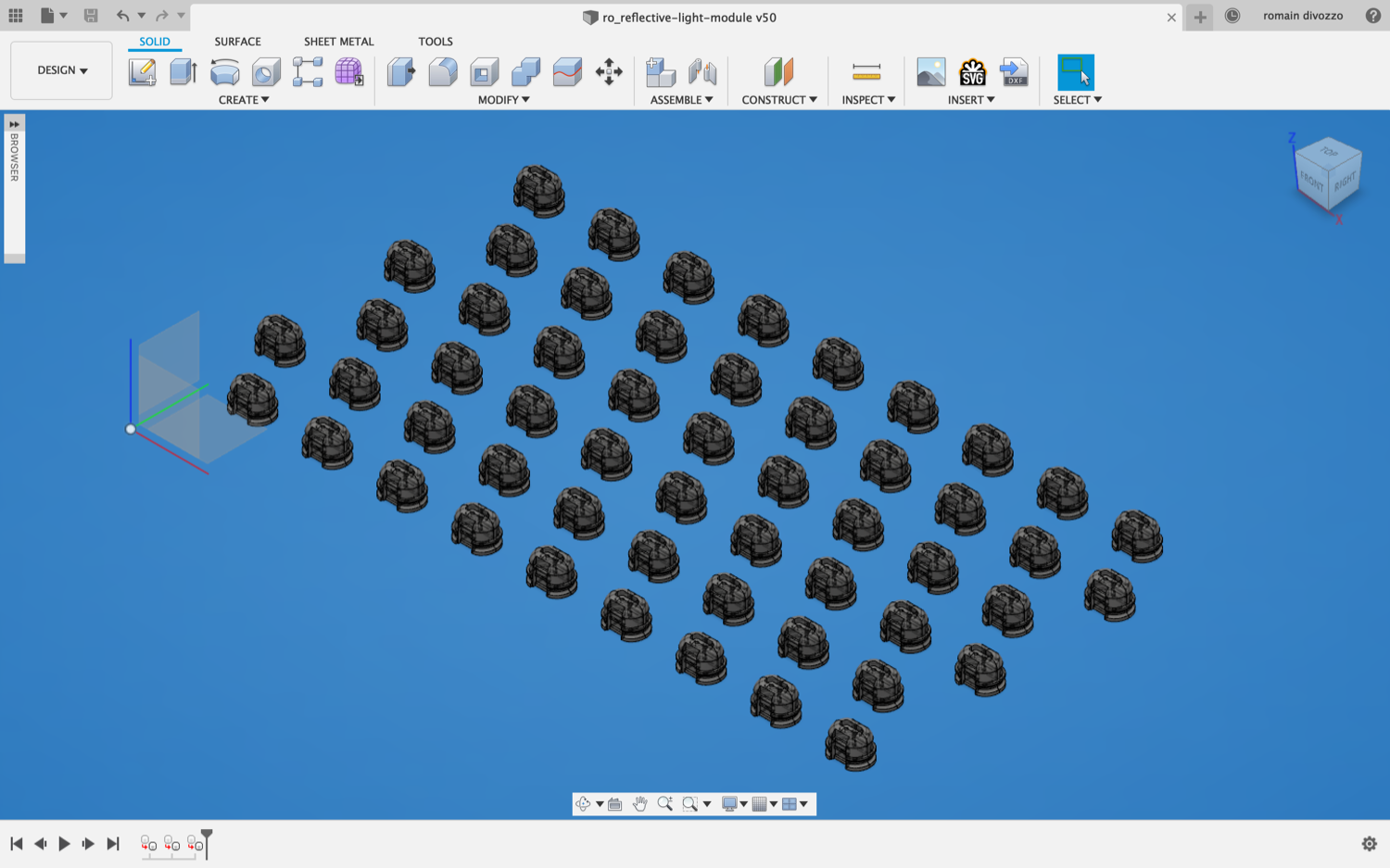
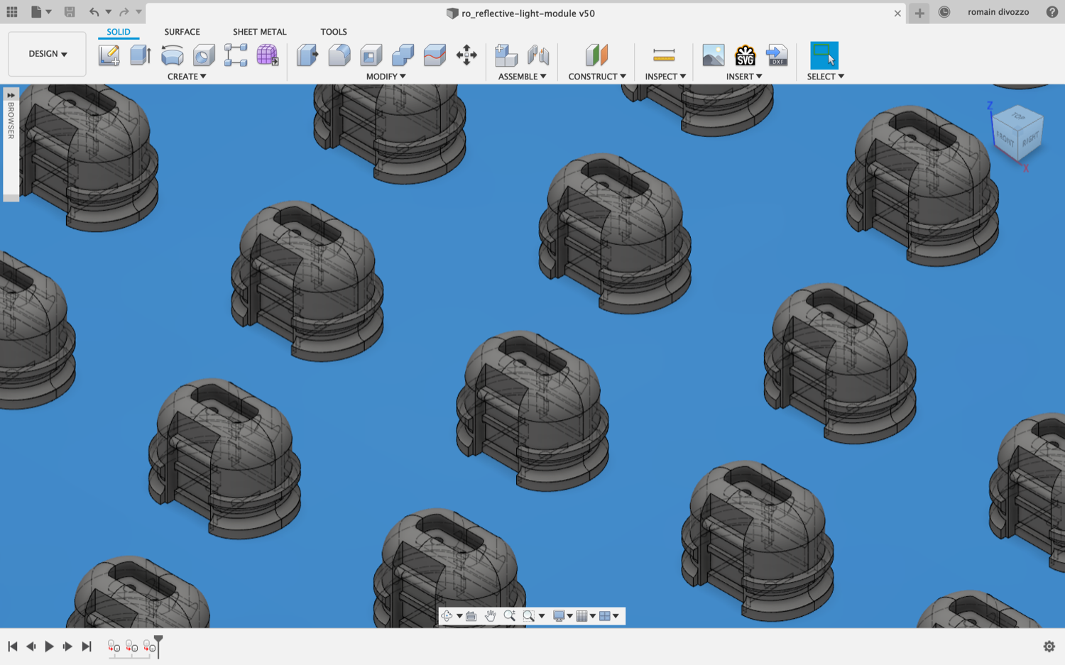
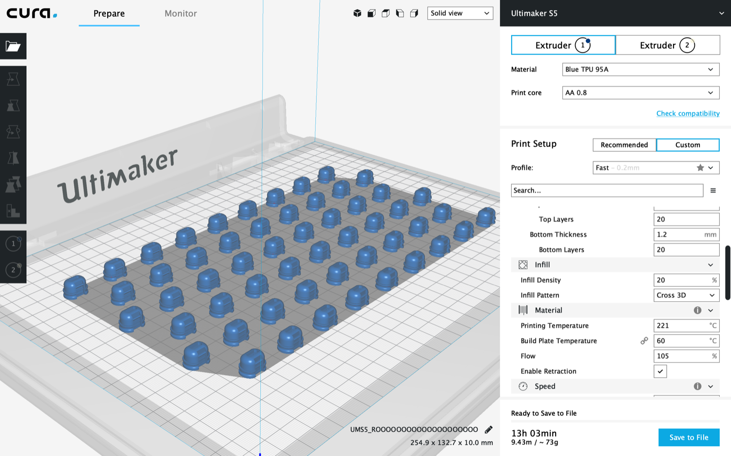
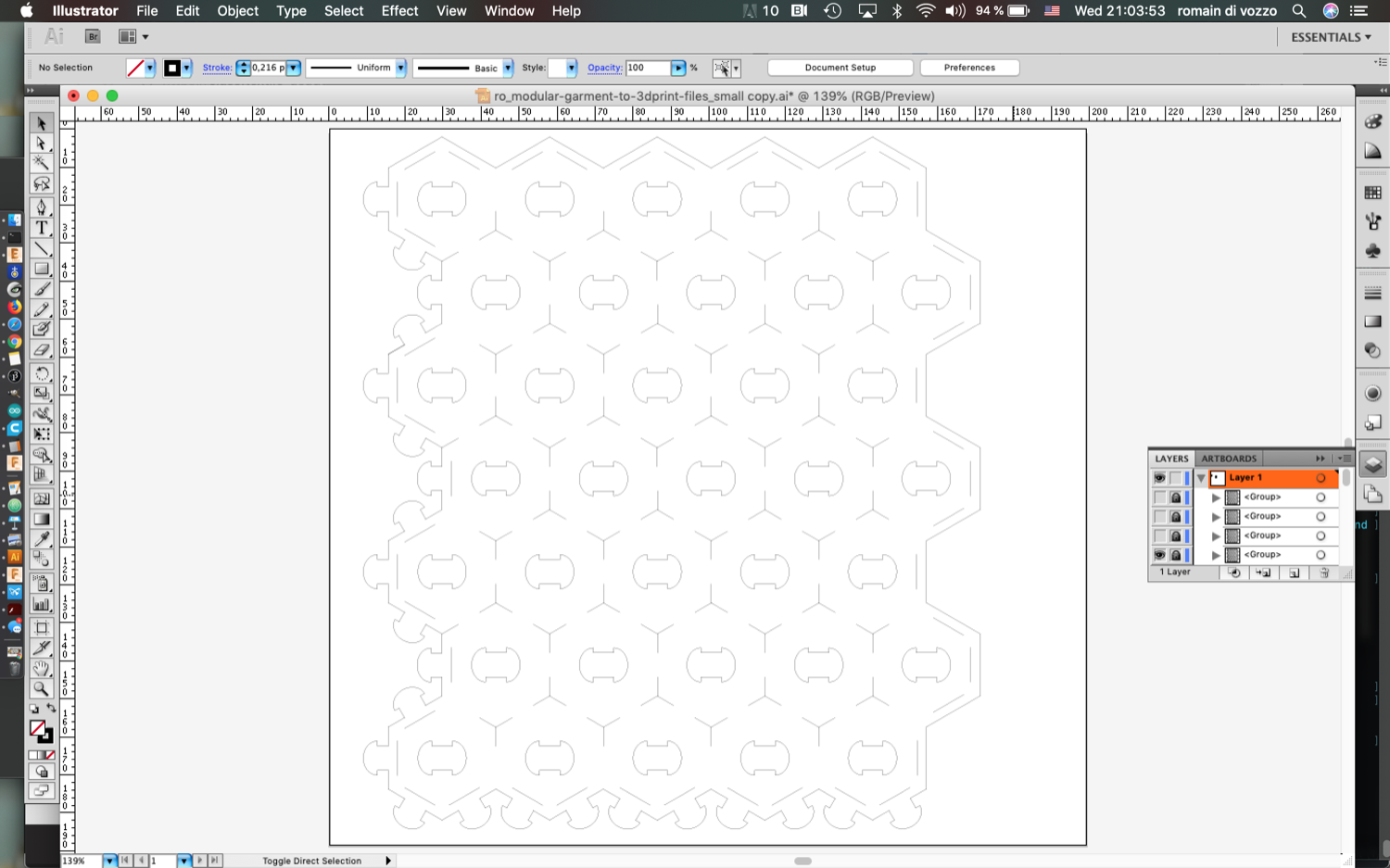
I have prepared a new file with 63 3D-printed press-fit connectors to be printed directly on fabric, on Ultimaker S5. FUSION 360 is weak when you have many objects on one scene. Really painful to see the rainbow-wheel endlessly rotating (that never appears on screenshots btw!)
5.28
5.29
3D Printed Press-fit Connectors
3D Printed Press-fit Connector
5.28
5.29
Beautiful view in Ultimaker Cura
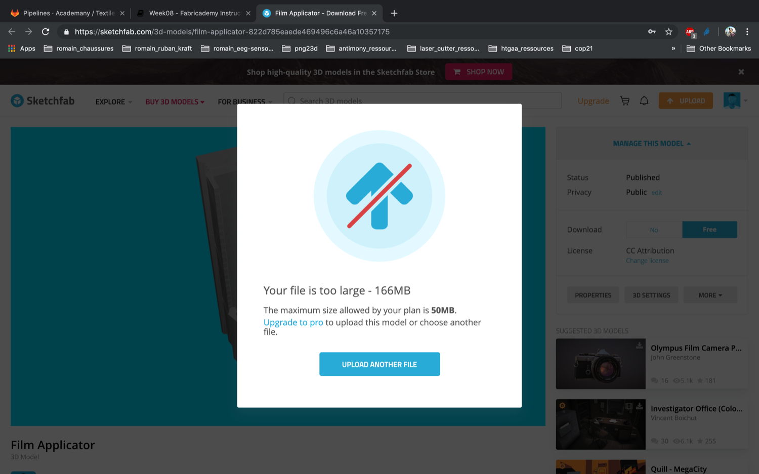
File is too heavy to be uploaded on Sketchfab…
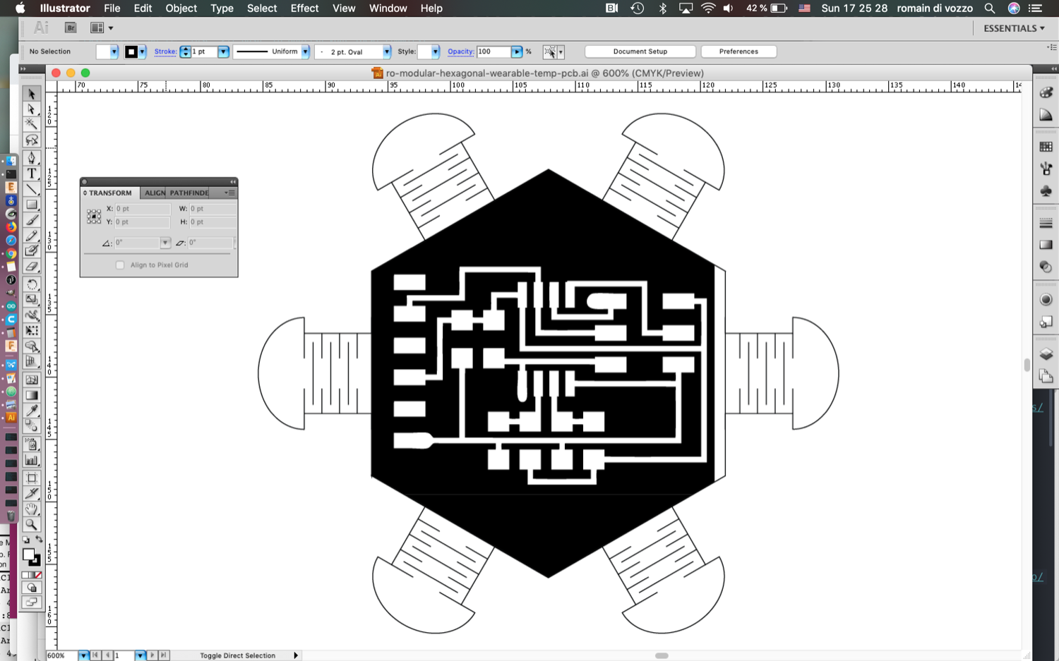
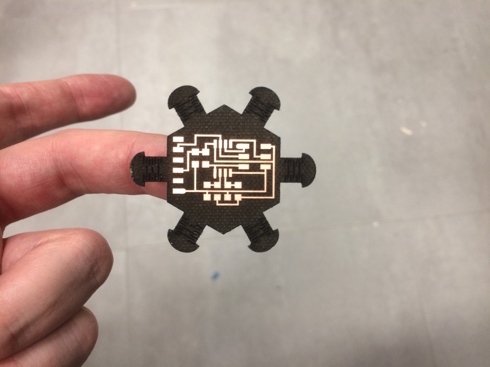
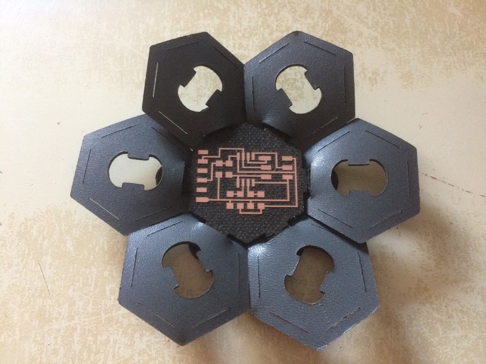
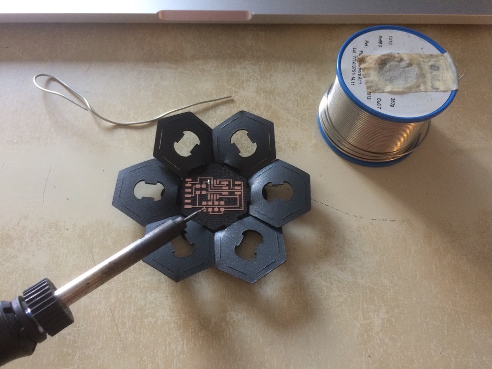
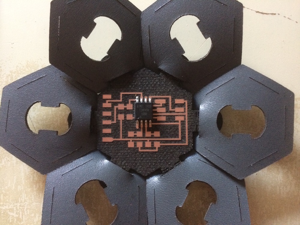
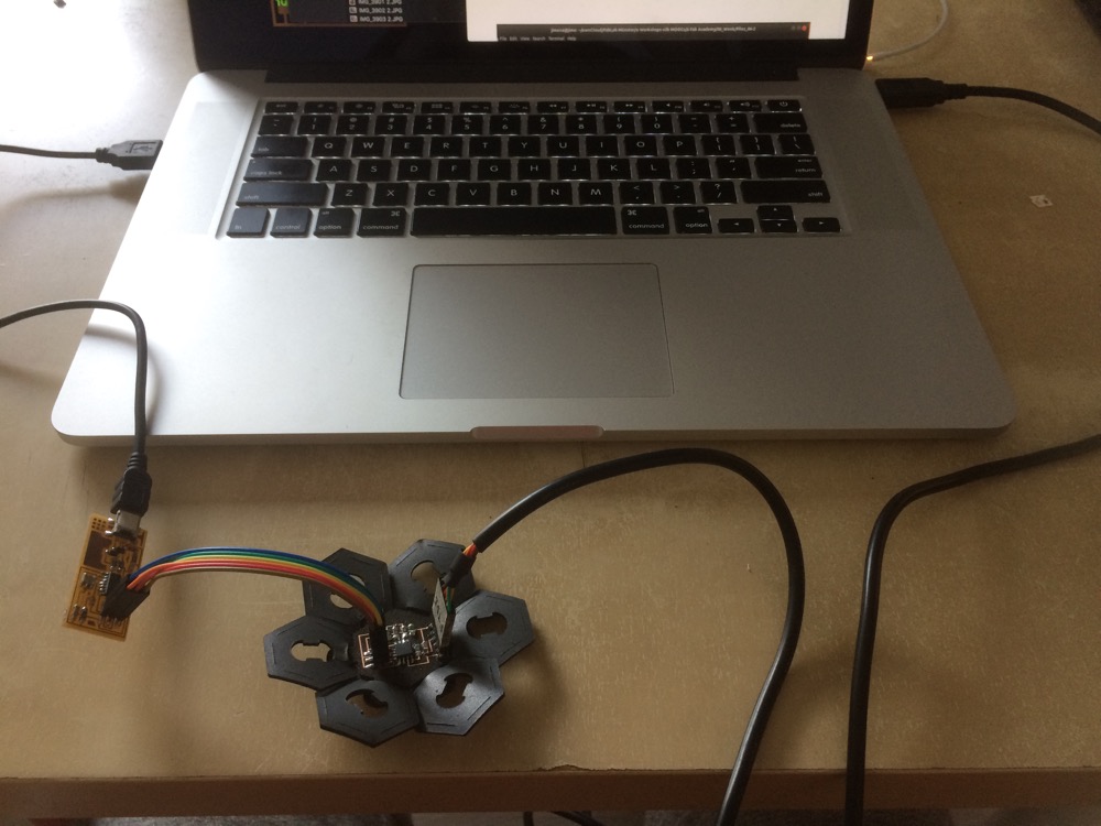
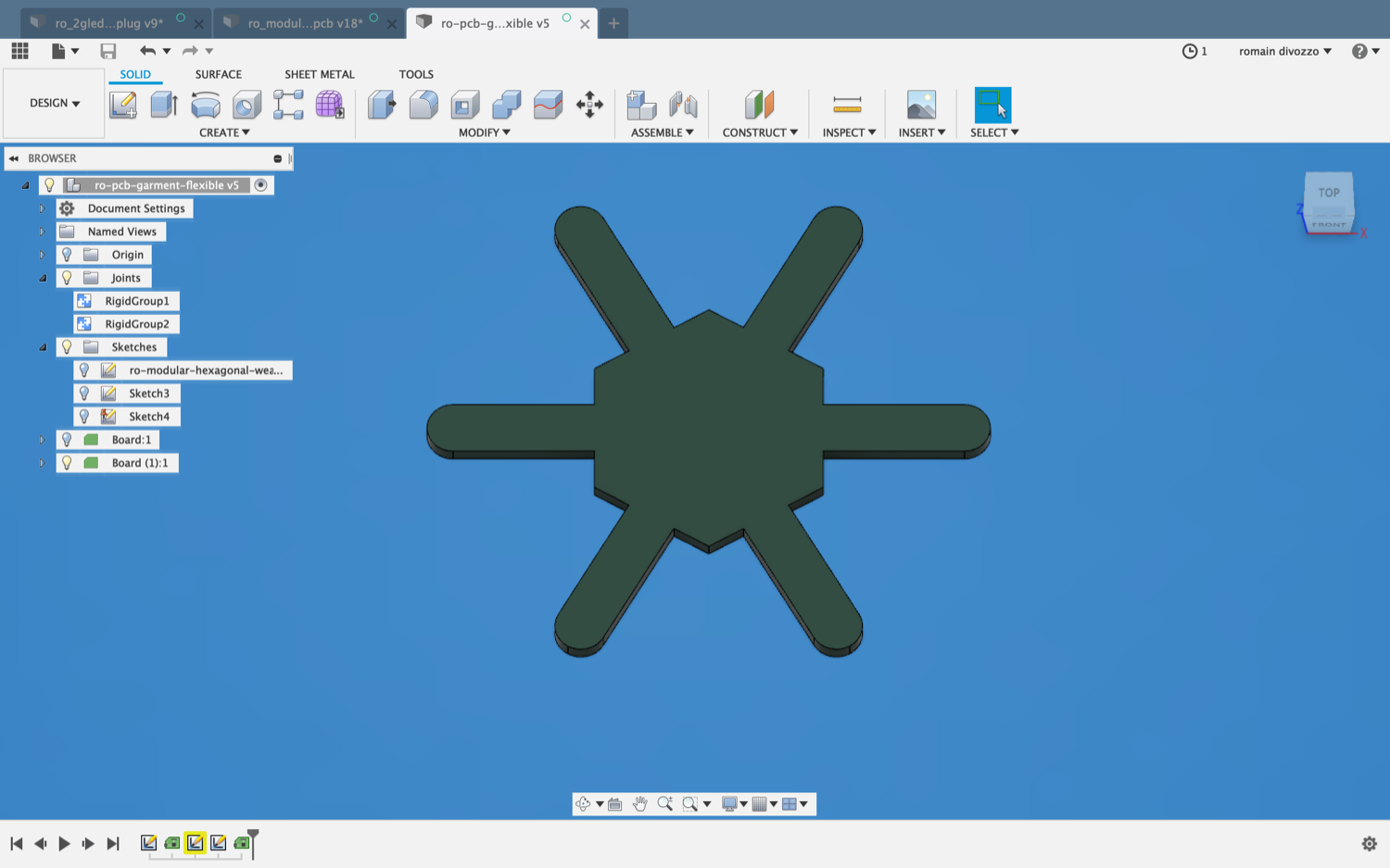
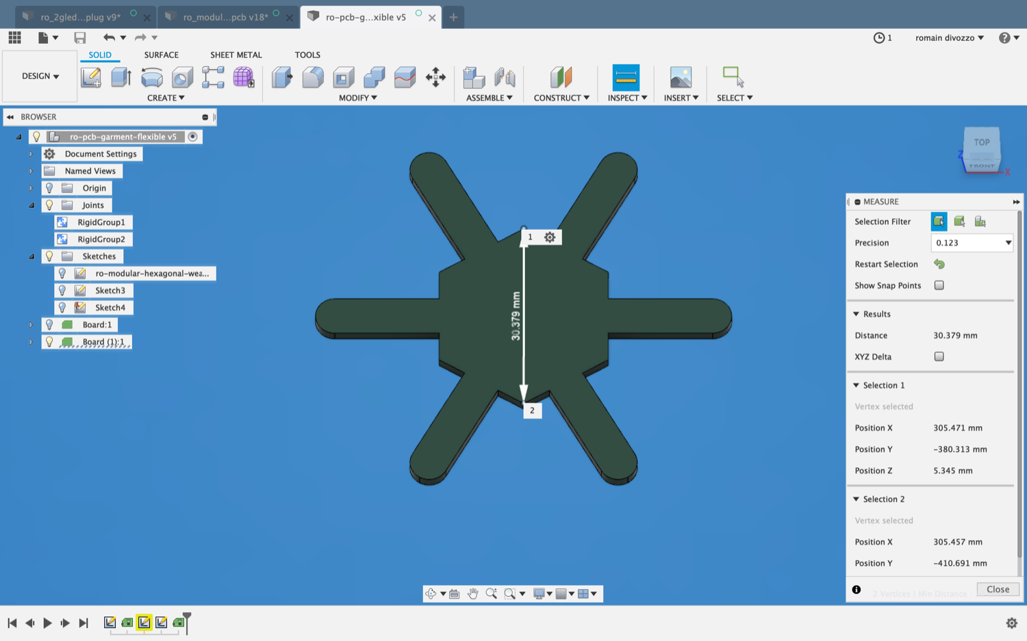
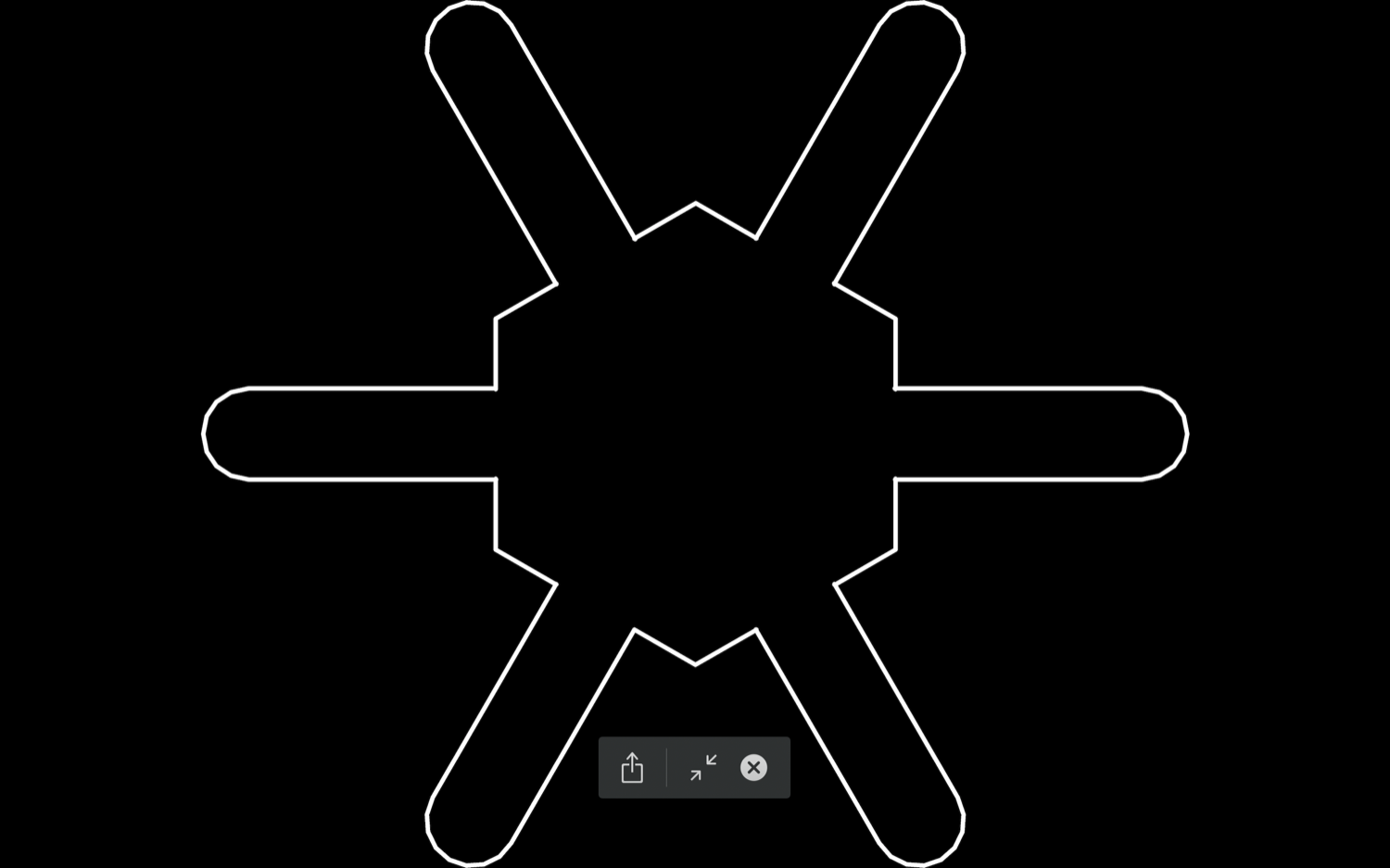
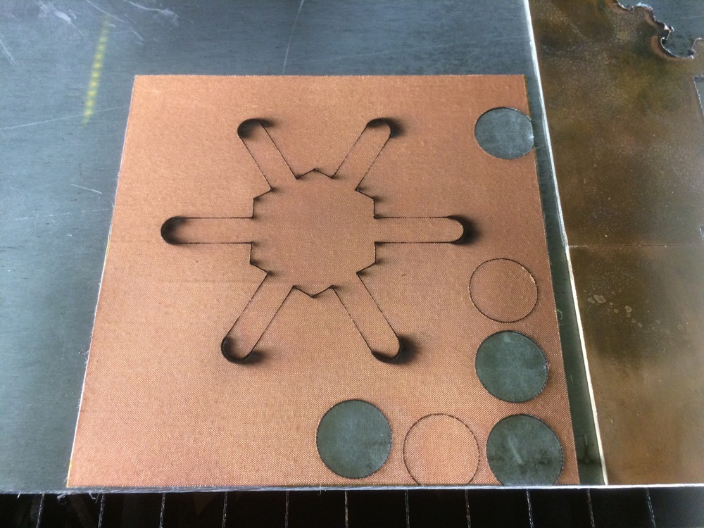
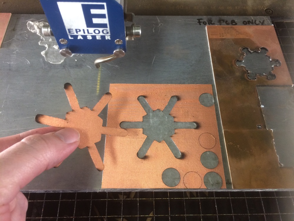
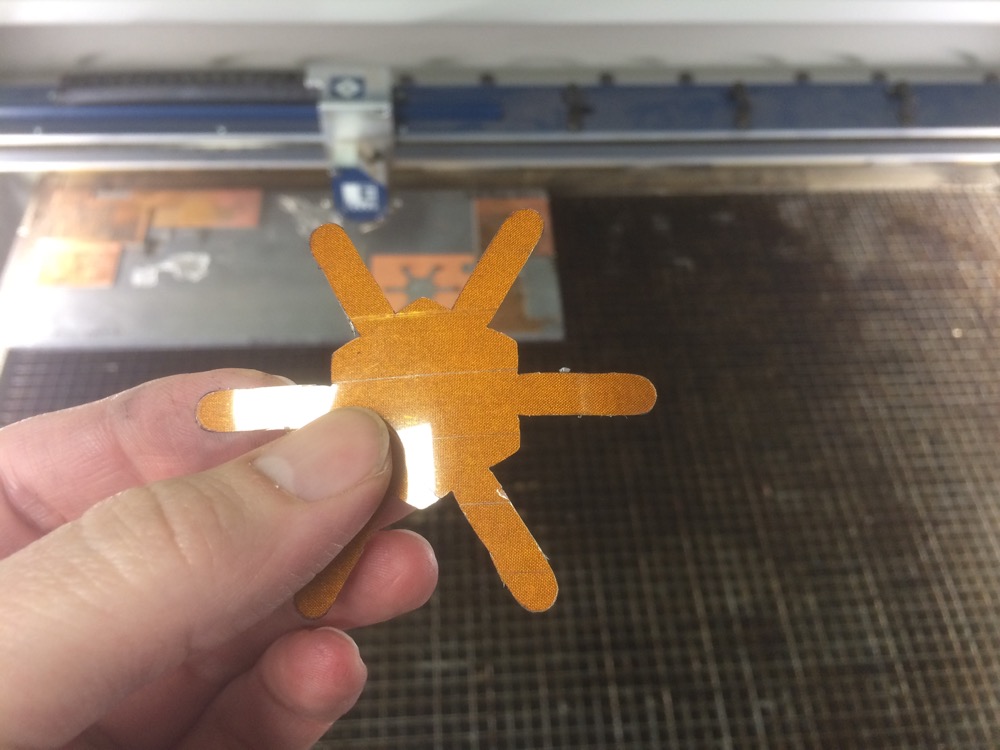
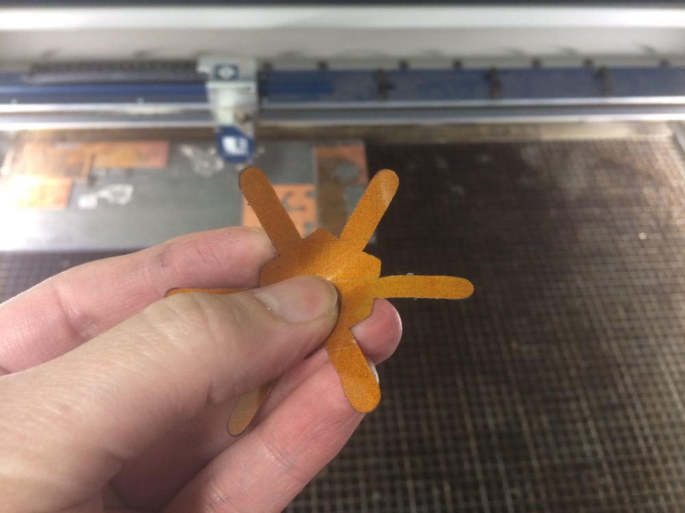
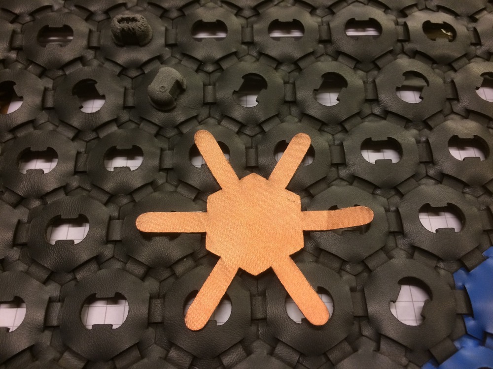
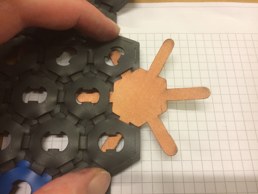
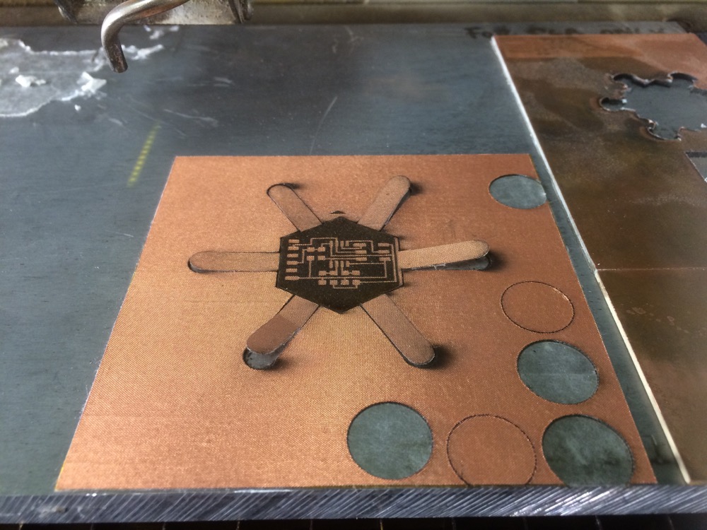
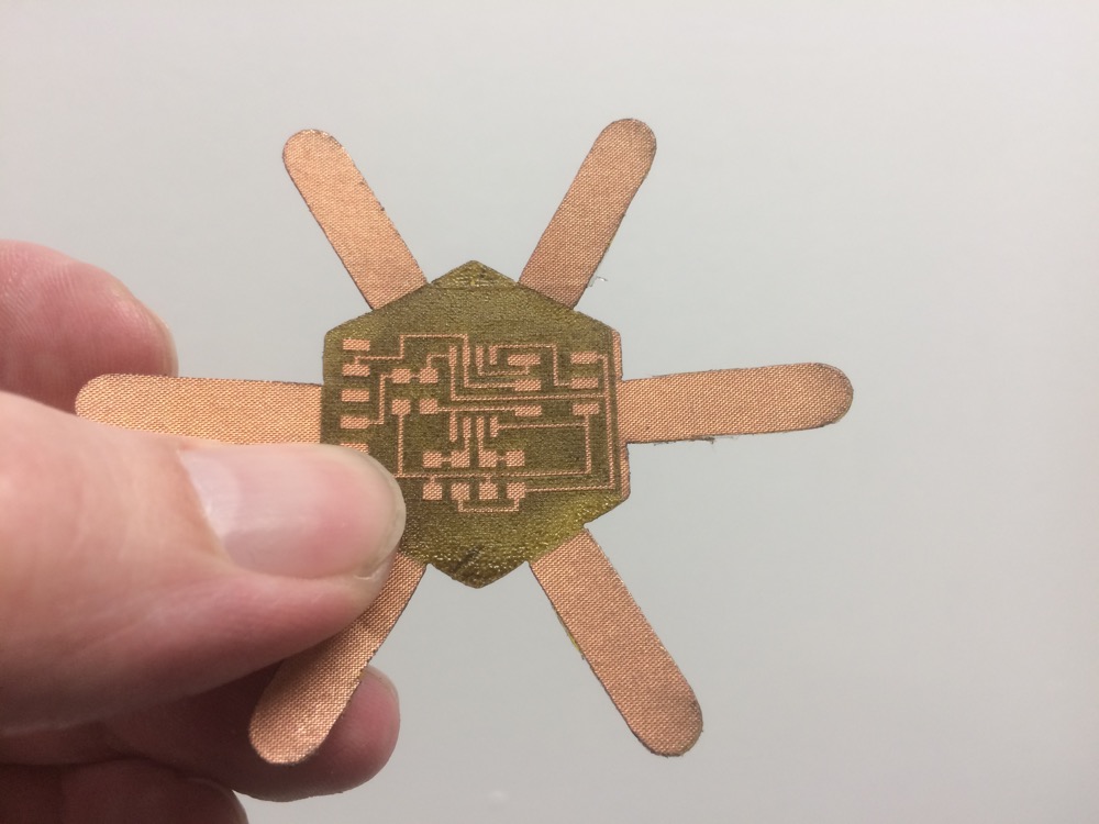
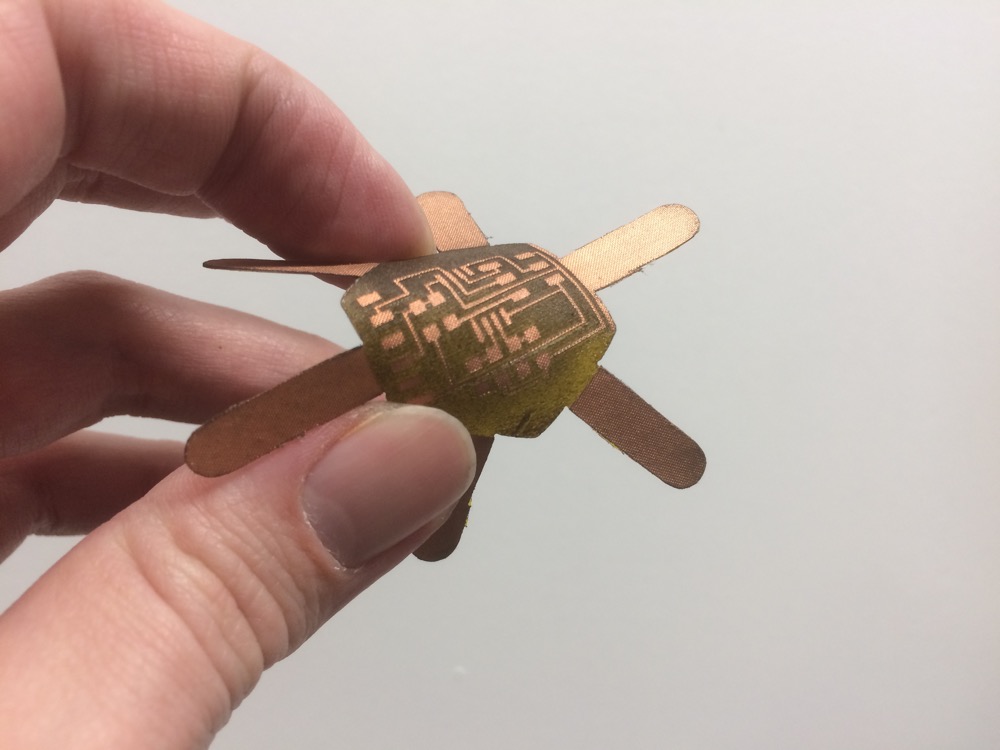
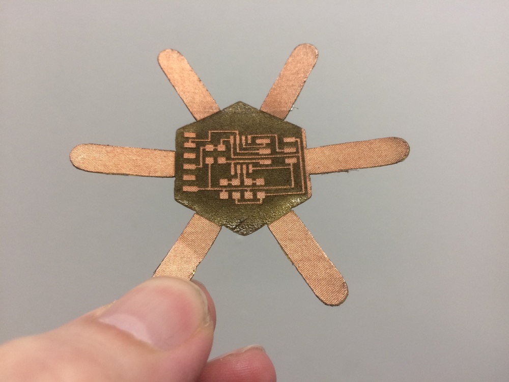
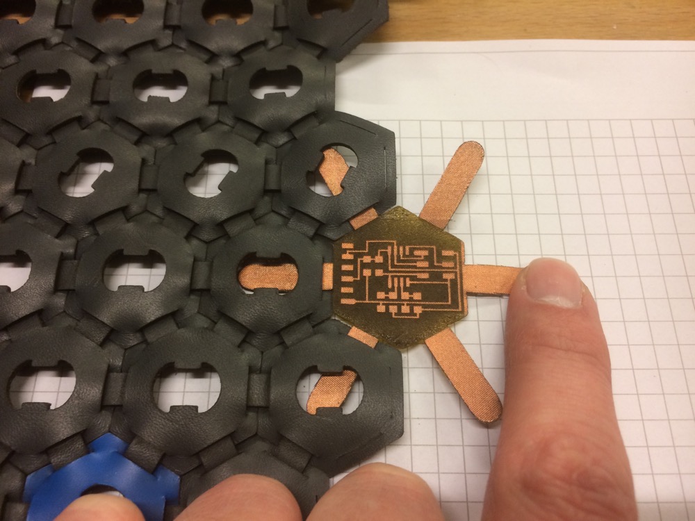
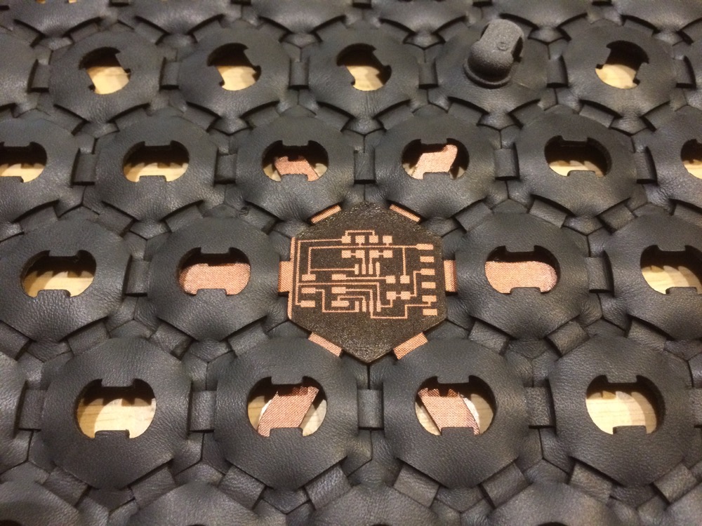
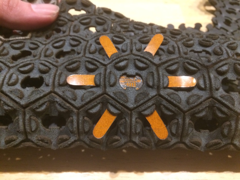
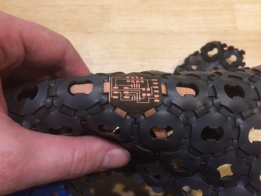
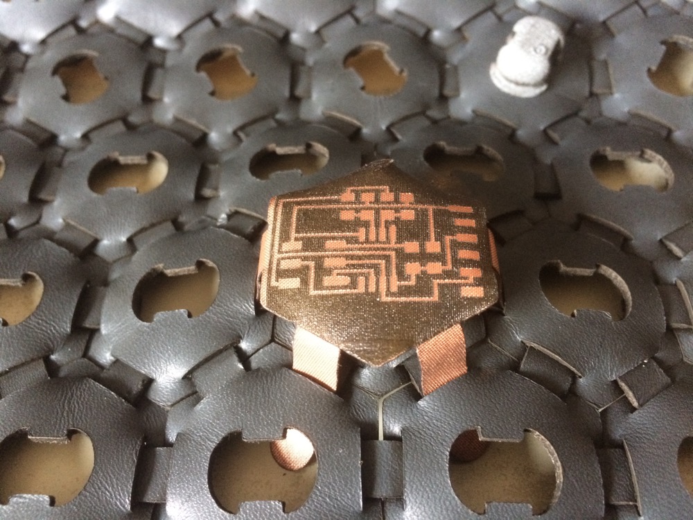
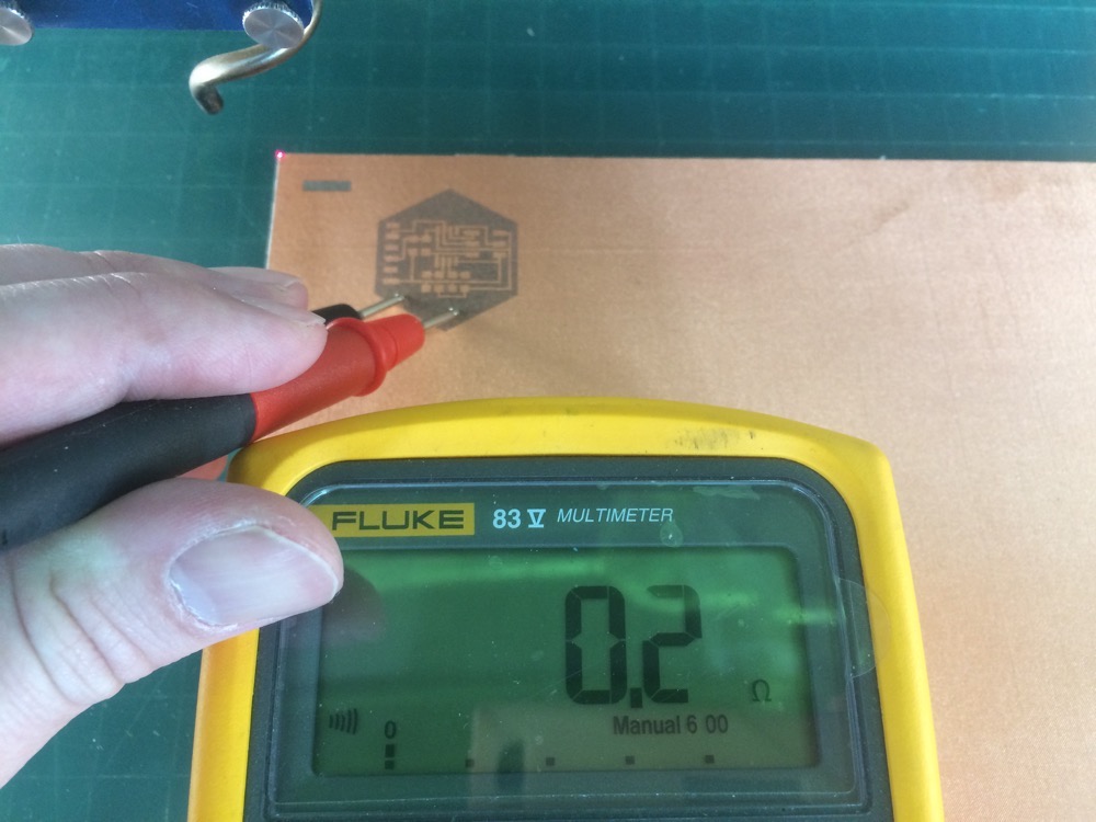
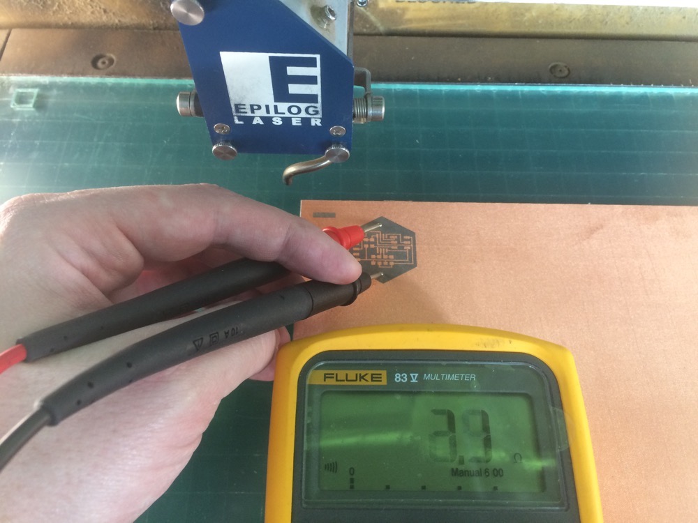
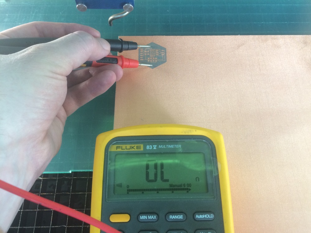
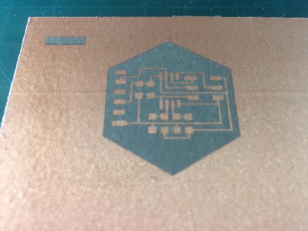
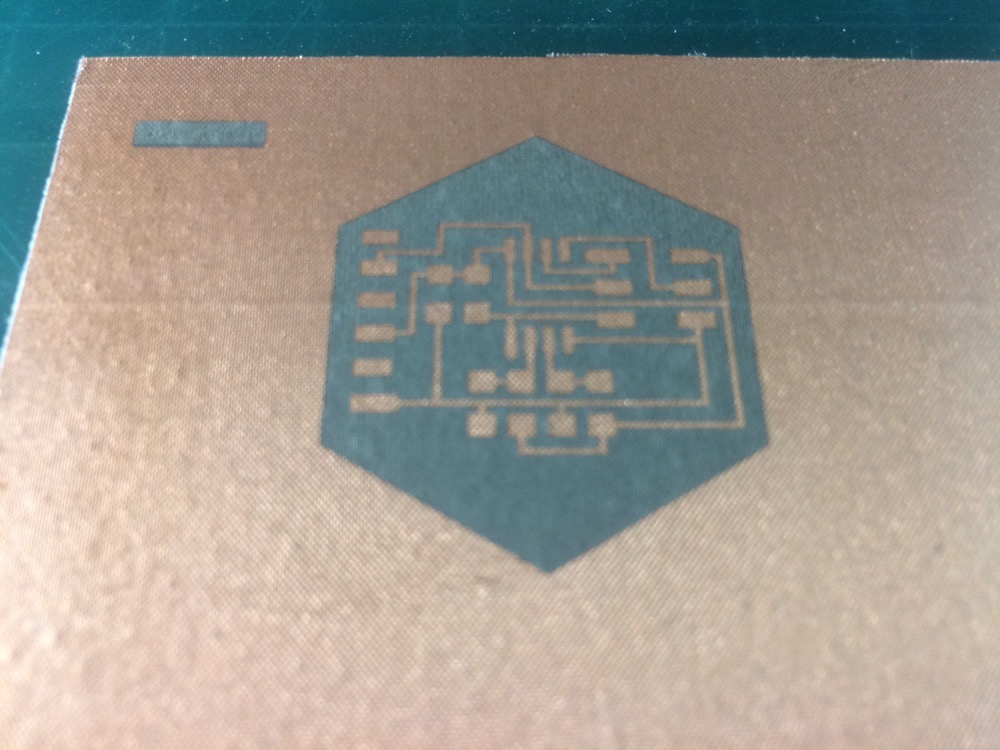
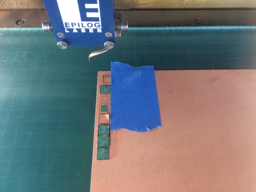
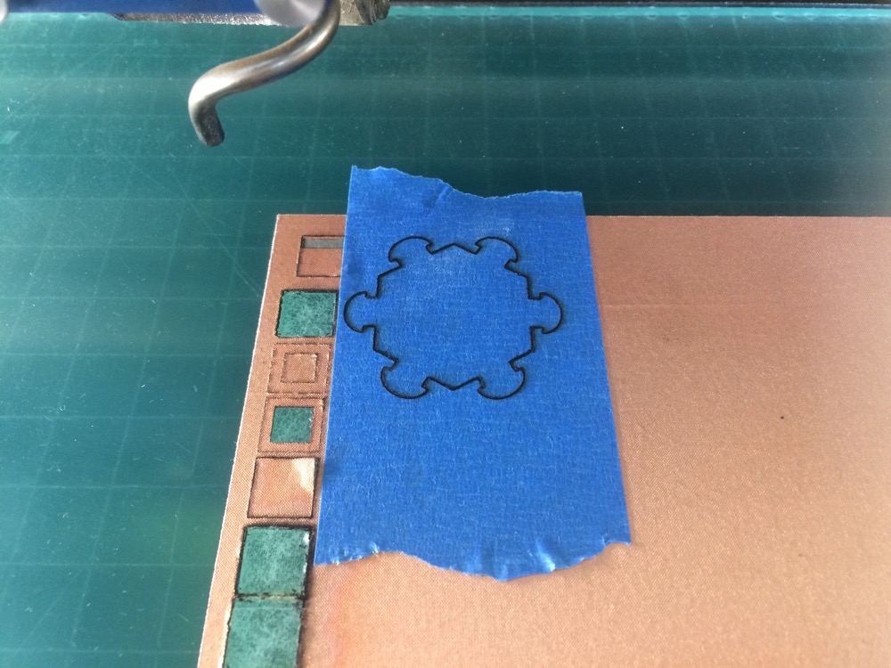
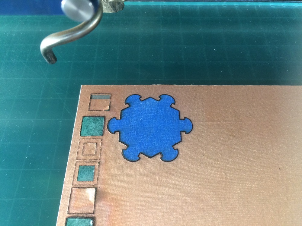
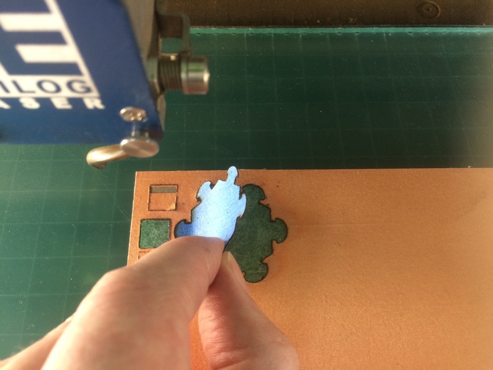
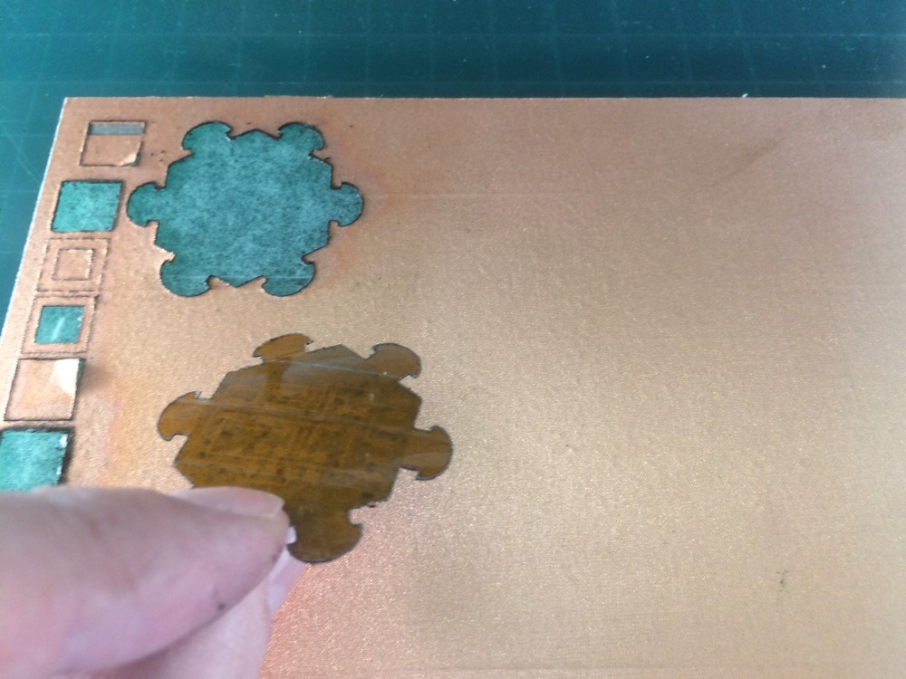
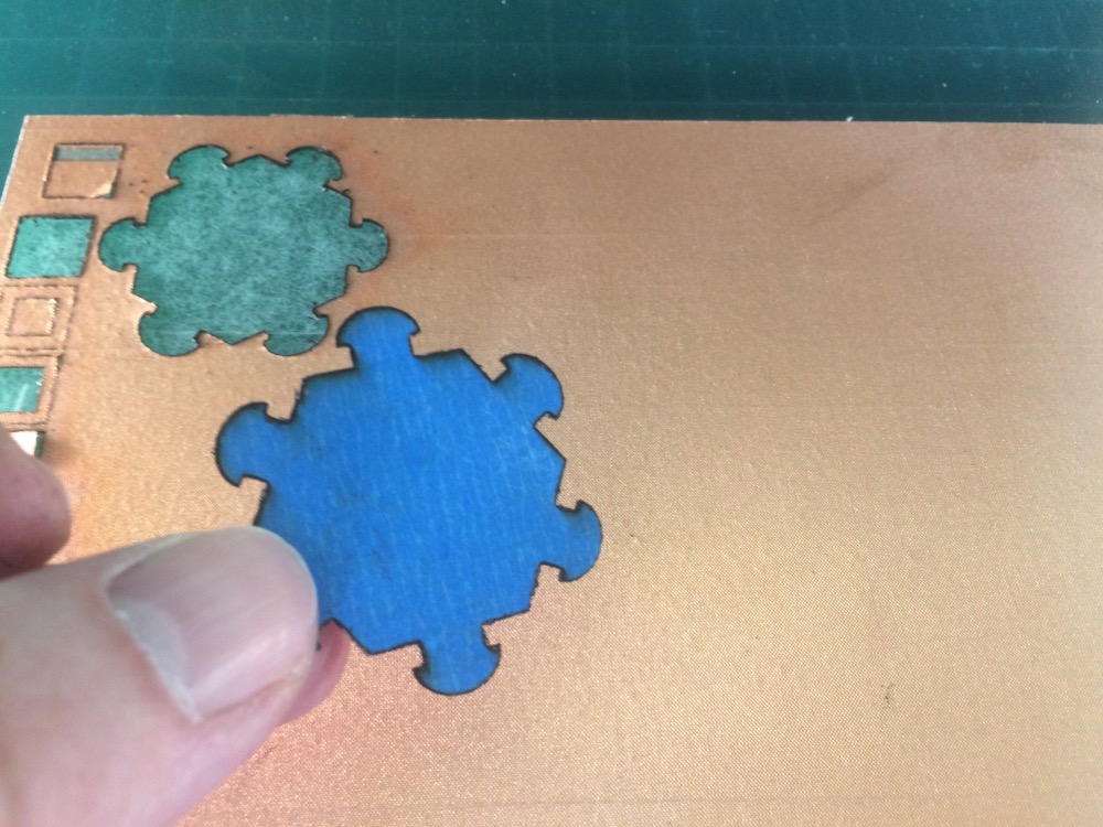
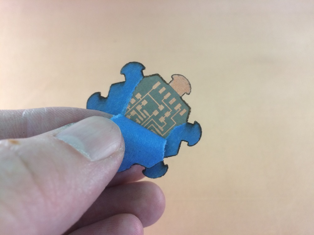
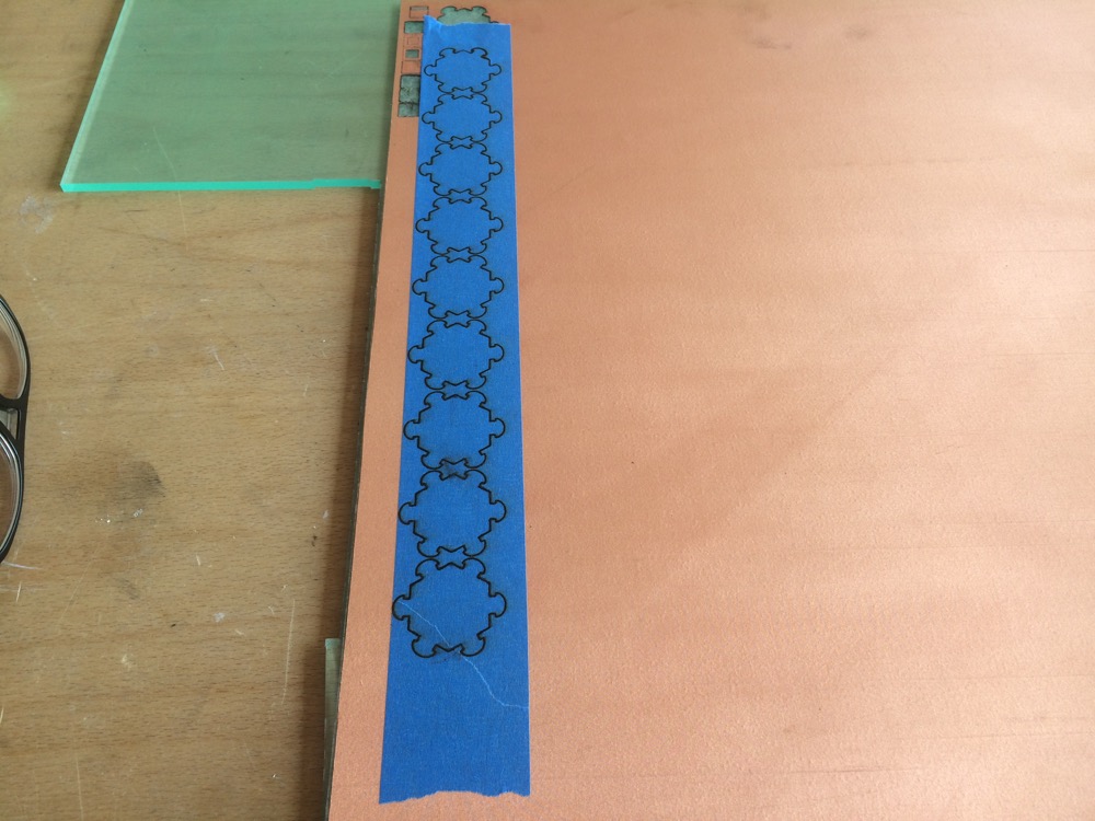
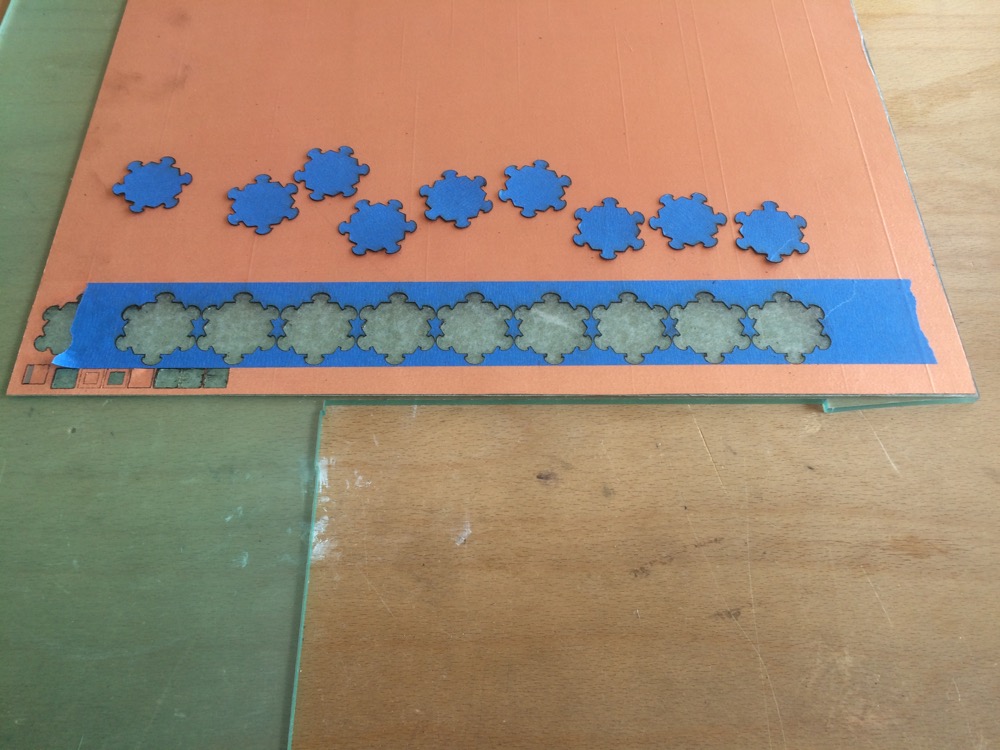
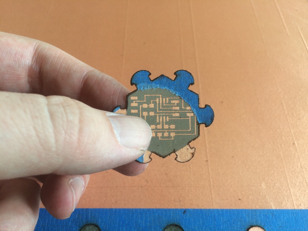
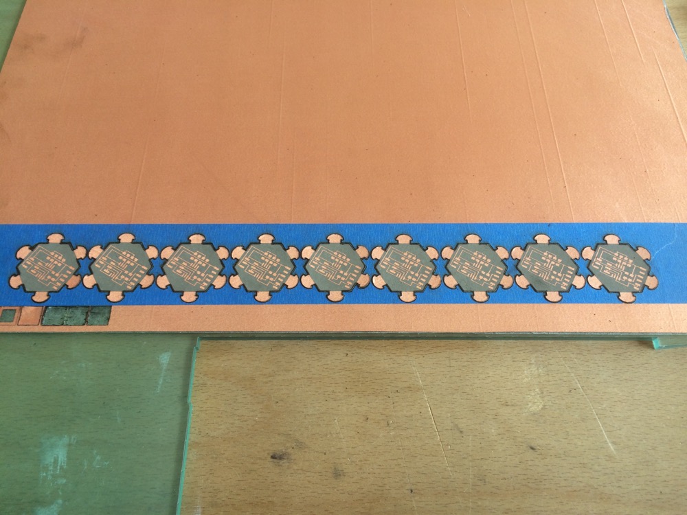
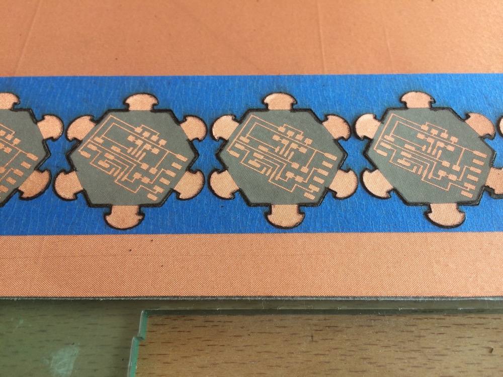
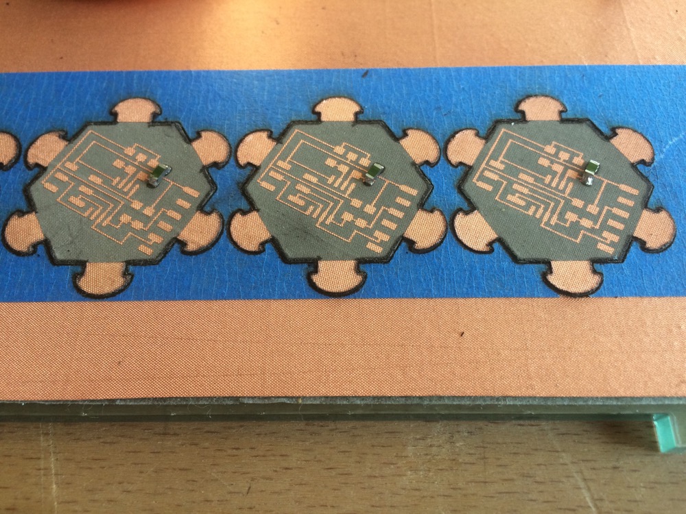
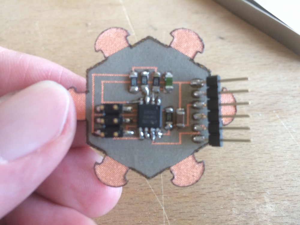
6/Following the path of adding digital functionalities to the garment, I electronically augmented the modular-reconfigurable-hexagonal module by virtually transfering the traces of an existing Temperature Sensor design on a virtual PCB pattern that included the press-fit connections in its design. I then laser-engraved the traces and laser-cut the contour of the pattern on a blank PCB at the exact same dimensions I had set up for the leather modules, and connected it to the leather modules. I noted that the shape of this pcb should follow a more distributed design.
6.1
Hexagonal Temperature-Sensor PCB Model with Flexture Branches to Connect to Modular Leather Garment
6.2
Hexagonal Temperature-Sensor PCB with Flexture Branches to Connect to Modular Leather Garment
6.3
6.4
6.5
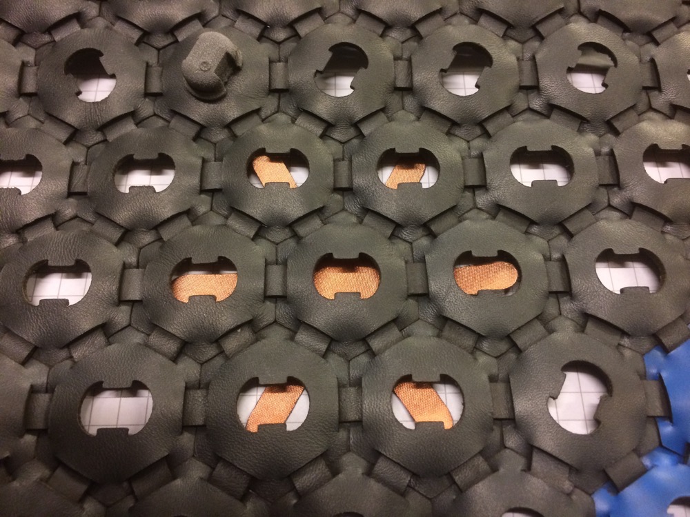
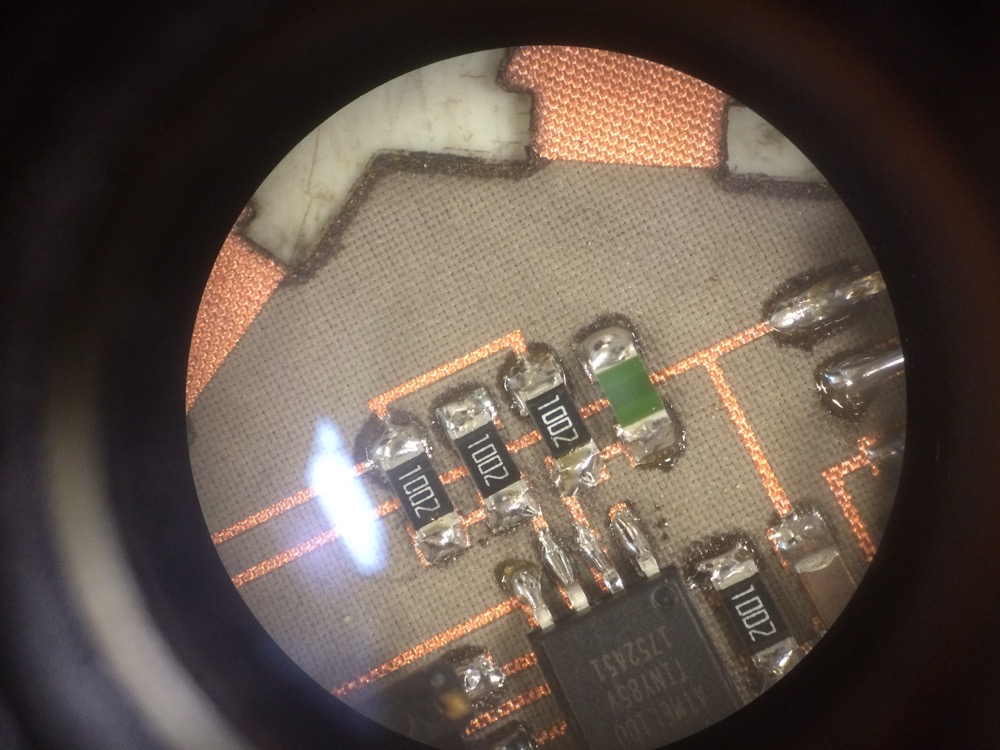
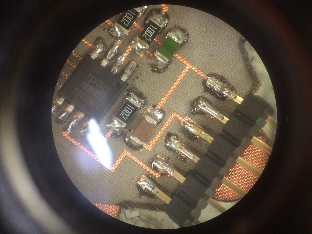
Hexagonal PCB stuffing
Hexagonal PCB stuffing
Hexagonal PCB stuffing
6.6
6.7
6.8
Hexagonal PCB stuffing
Hexagonal PCB stuffing
Hexagonal PCB programming
ADD PICTURE
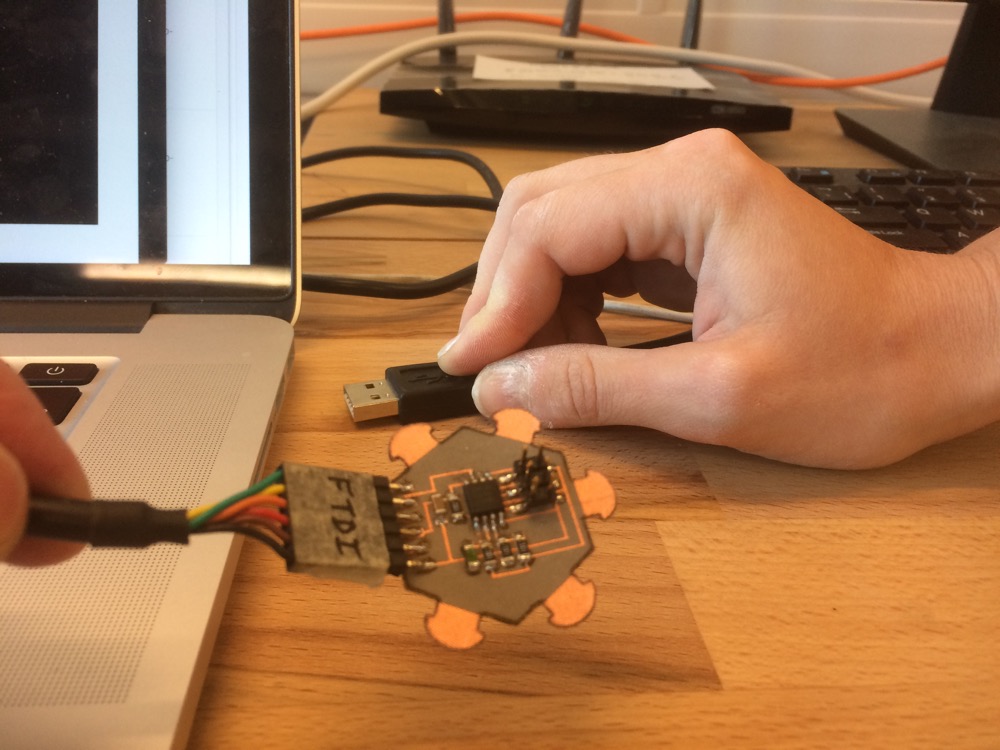
Here is the interface that shows what comes out of the temp sensor through ftdi communication. This is a code from N.Gershenfeld. I just changed a small part of the code to change the size of the window, to change the size of the text and the colors.
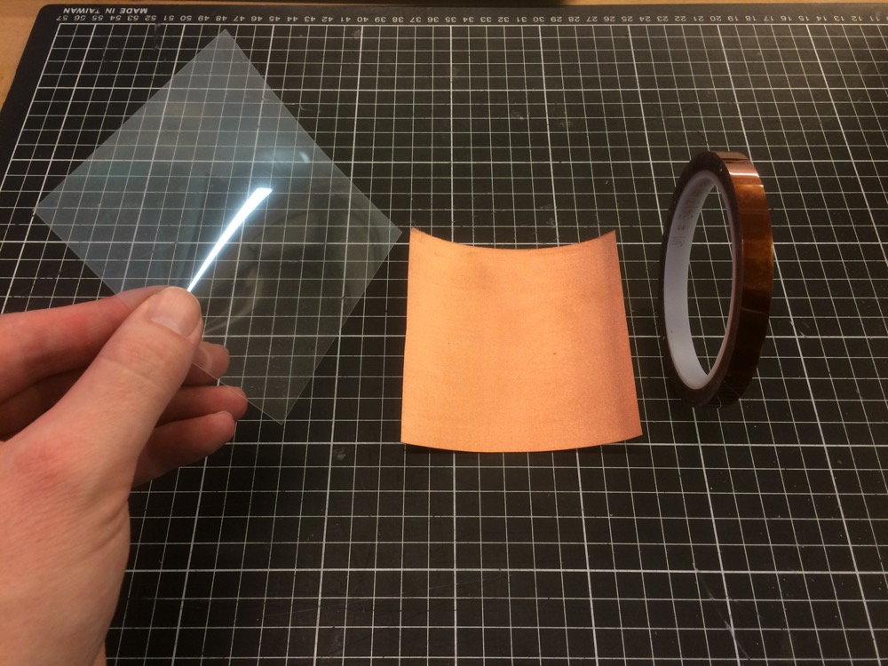
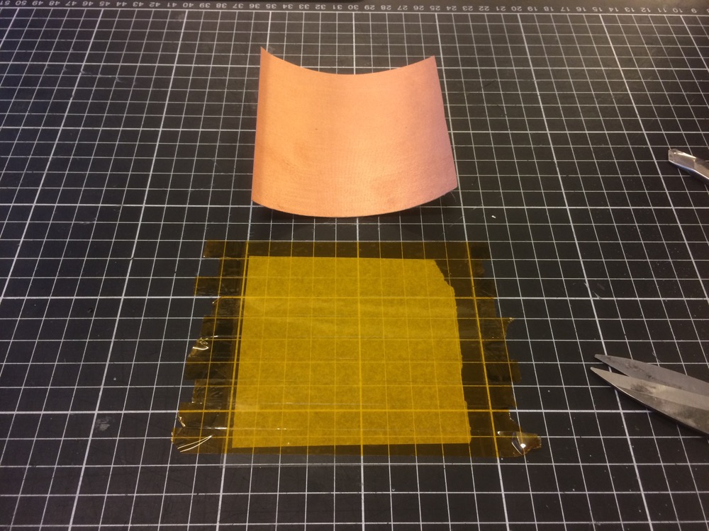
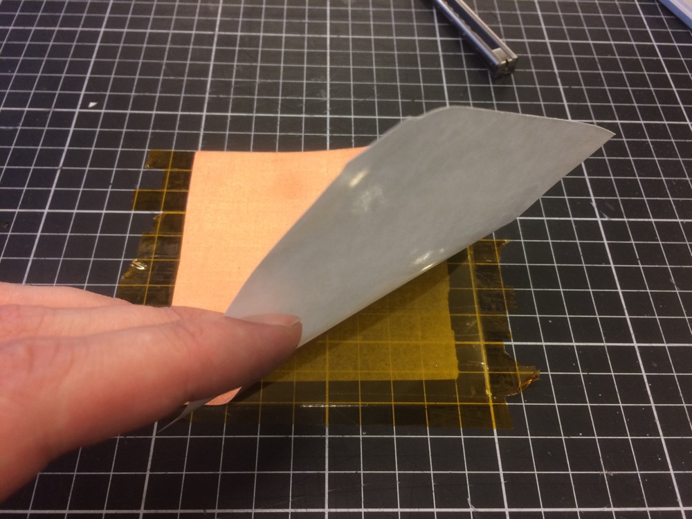
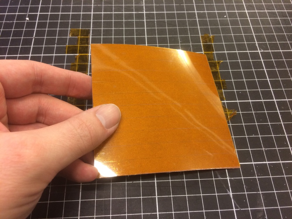
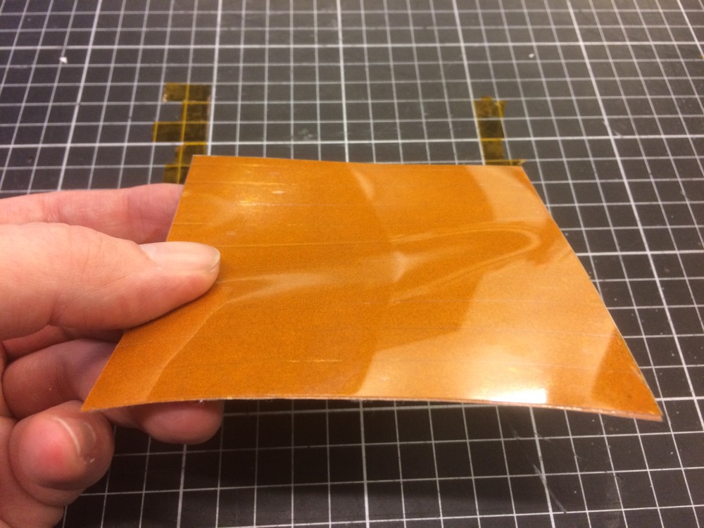
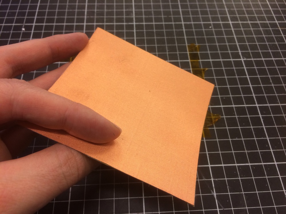
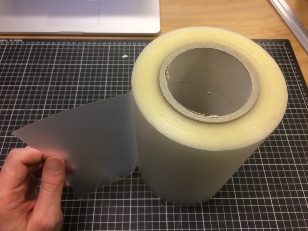
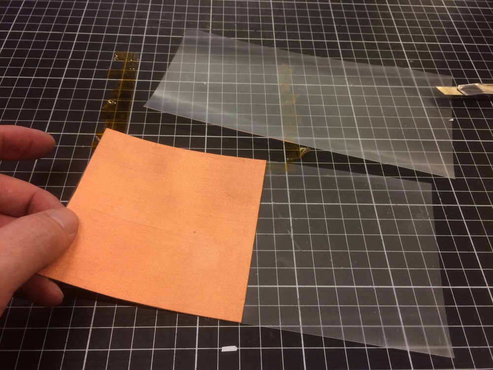
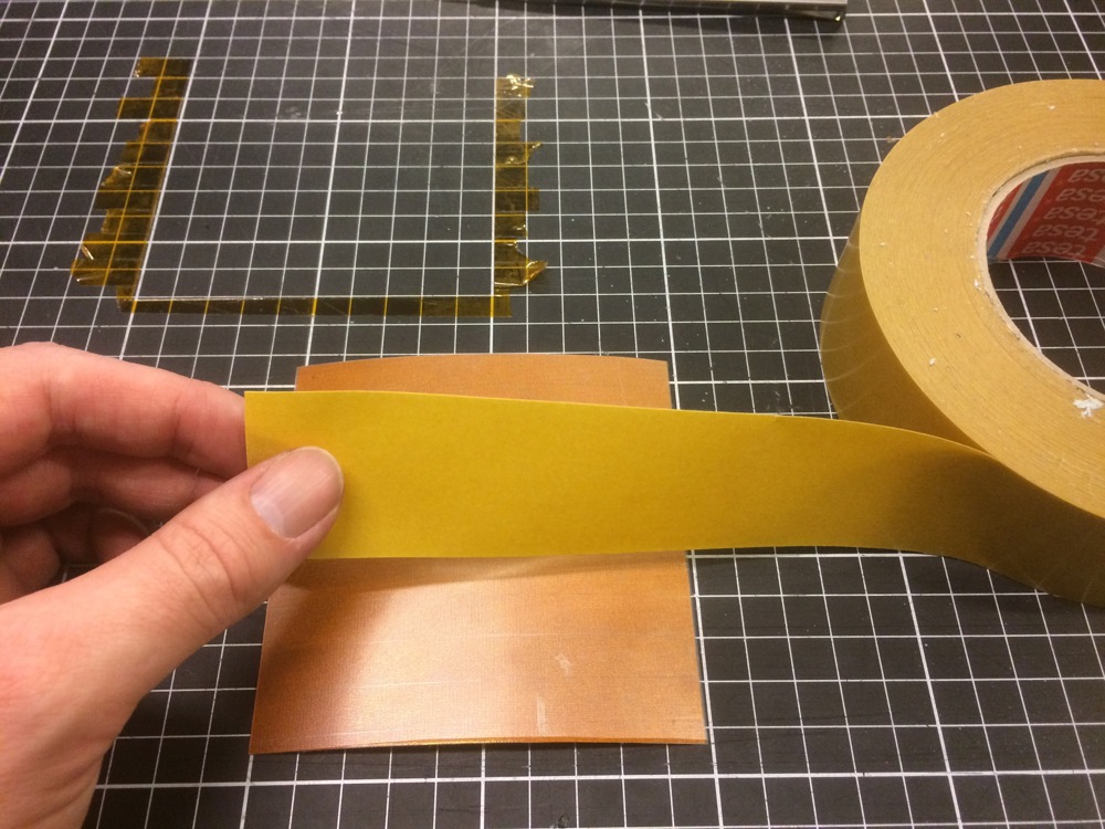
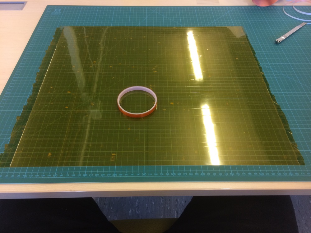
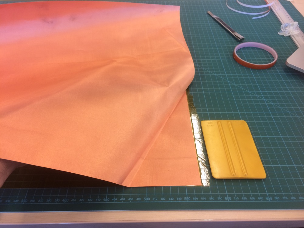
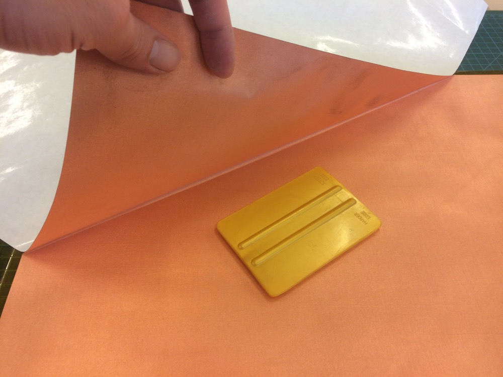
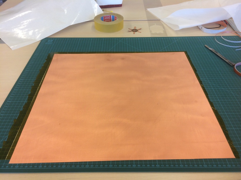
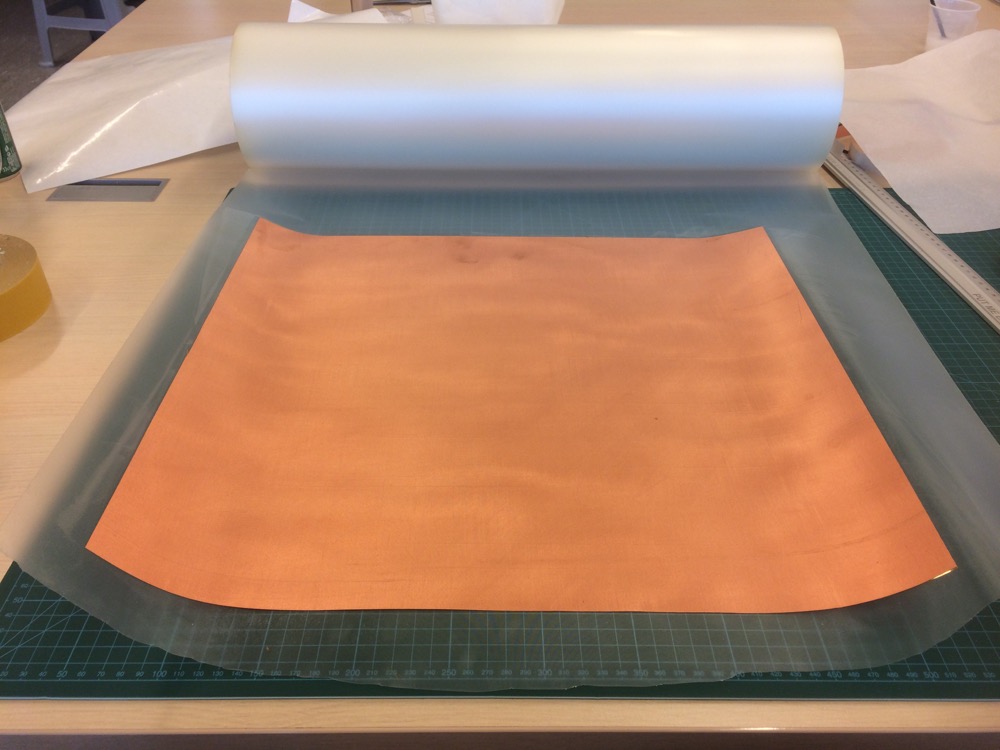
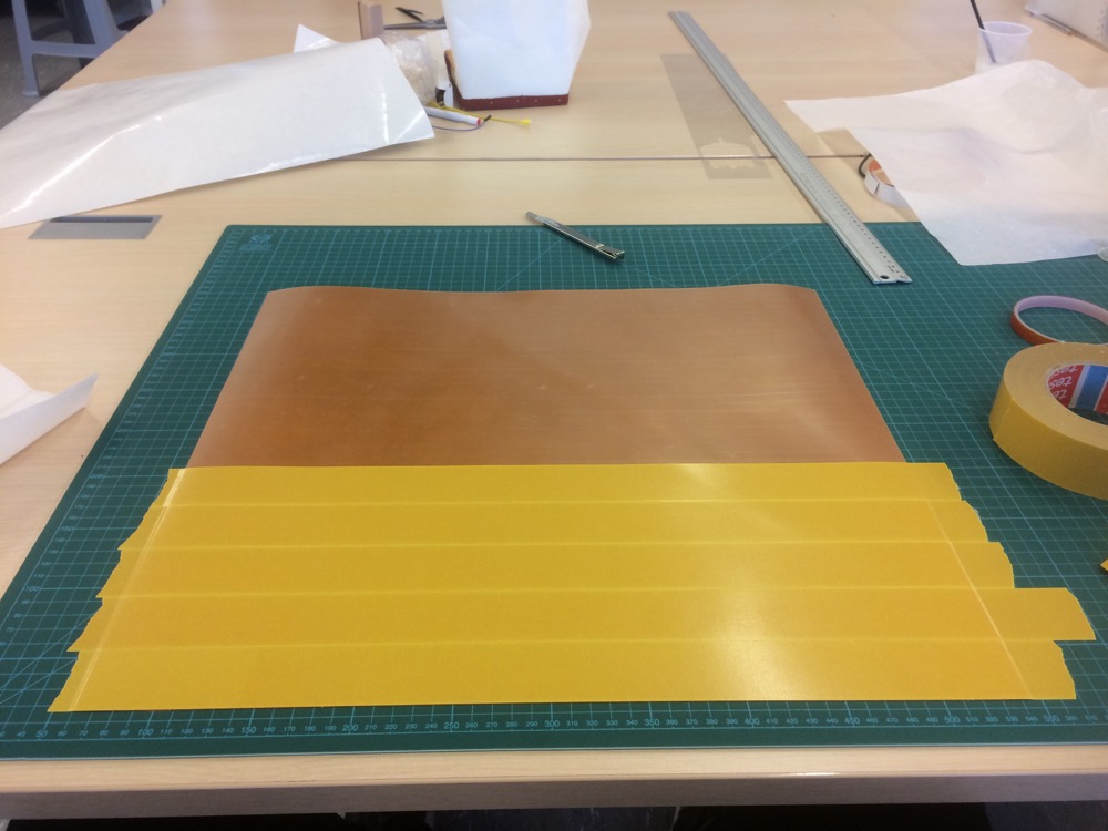
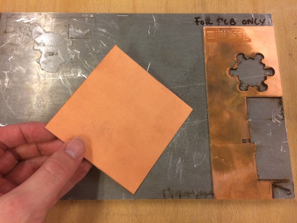
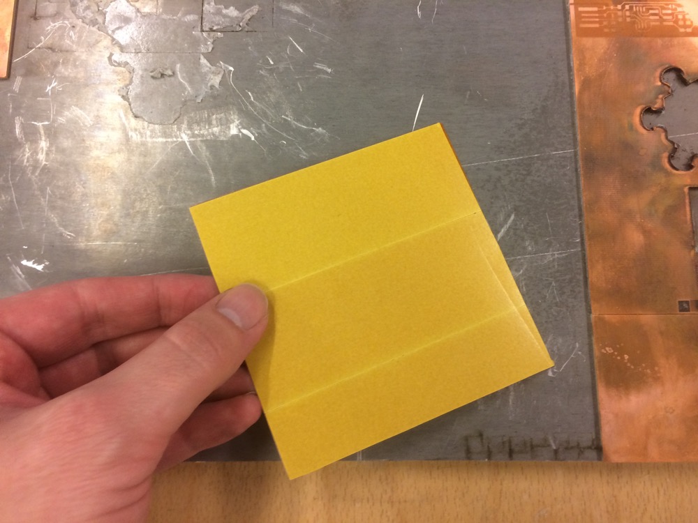
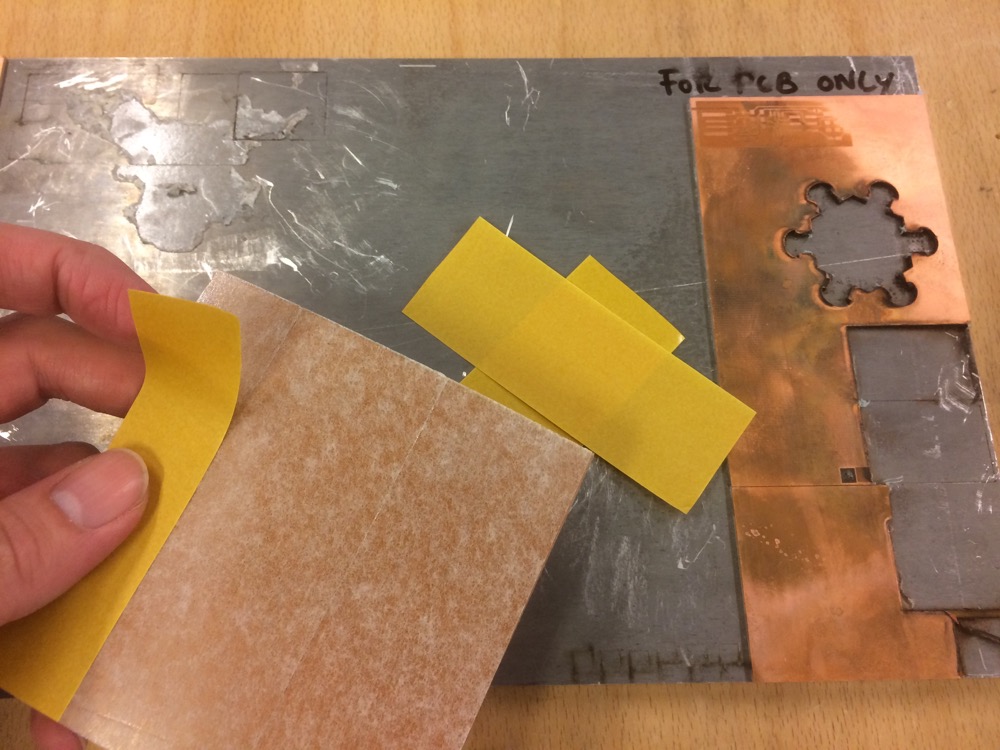
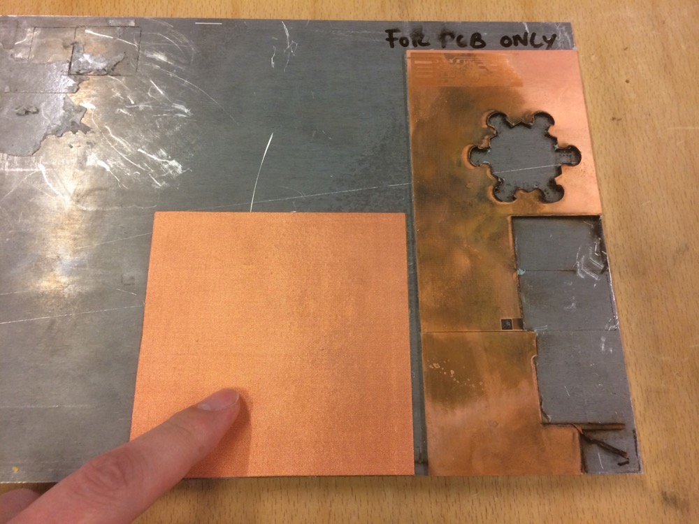
7/ Having FR4 electronic modules made of 1.6mm thick epoxy-resin and copper wasn’t completely satisfying in terms of flexibility. In this case, epoxy was too rigid. I had to think of a way to assemble available materials in the fablab to make a custom-flexible surface where to solder electronic components. And it had to resist laser-cutting and stay flat during the cut. Camille (my Fabricademy student) needed the same kind of substrate for her final project. I then asked her to make some soldering tests on the copper-shield, and on my side, I started to assemble layers of the following materials to make a flexible PCB substrate: copper-shield (top layer), Kapton (second layer), PET-sheets (third layer), non-permanent transfer-tape (fourth layer) and double-sided tape (fifth layer). Kapton is Polymide, and it can resist very high temperatures (around 200C as far as I remember) so it will be the bottom of my substrate.
7.1
7.2
7.3
5 layers Home Made Flexible PCB
Sticky Kapton on PET
Sticky Copper-Shield on Kapton
7.4
7.5
7.6
PET + Kapton + Copper-Shield
PET + Kapton + Copper-Shield
Copper-Shield + Kapton + PET
7.7
7.8
7.9
Sticky Transfer Tape
Copper-Shield + Kapton + PET on Sticky Transfer Tape
Adding Double-Sided Tape on Sticky Transfer Tape
7.10
7.11
7.12
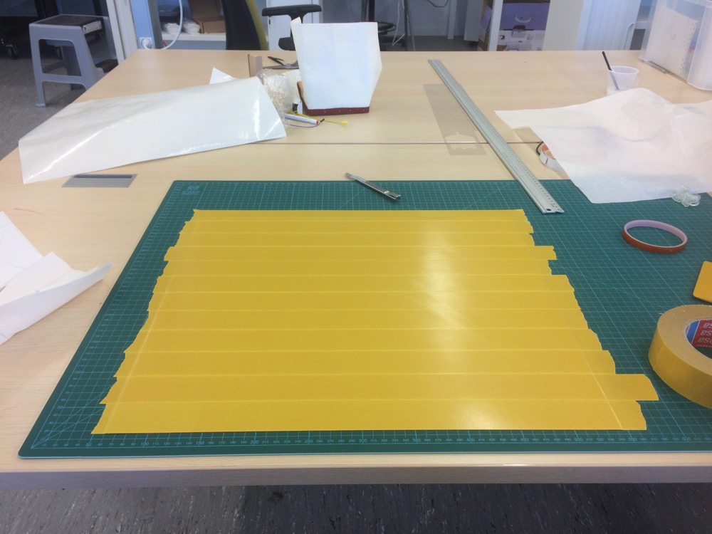
Assembling a wider substrate
Assembling a wider substrate
Assembling a wider substrate
7.13
7.14
7.15
Assembling a wider substrate
Assembling a wider substrate
Assembling a wider substrate
7.16
7.17
7.18
Assembling a wider substrate
Assembling a wider substrate
Assembling a wider substrate
8/Designing a modular flexible PCB that can be embeded into the hexagonal pattern I picked up became possible. It took a while before I could see it clearly and actually sketch it. I chose to focus on light emission for now. But think that you could embed many outputs and inputs on it, like temperature, or sound (see the tiny-press-fit-speakers I have designed LINK TO COME).
8.01
8.02
8.03
8.04
PCB Design in Fusion
PCB Design in Fusion
PCB Traces in Eagle
PCB .png Traces to laser-cutter
The version of the flexible PCB below can be superposed to the leather modules and its extensions can be inserted into the gaps in each leather module that receives the connectors. Wether you want to add it face up or face down the modular garment it works. Easy to insert, easy to remove. It needs to be redesigned with shorter legs but it works for now. My intention is to have each of the 6 branches connected to six 3D printed press-fit connectors via a circuit engraved on its legs. I am not far from this but not there yet.
8.1
8.2
8.3
blabla
blabla
blabla
8.4
8.5
8.6
blabla
blabla
blabla
8.7
8.8
8.9
blabla
blabla
blabla
8.10
8.11
8.12
blabla
blabla
blabla
8.13
8.14
8.15
blabla
blabla
blabla
8.16
8.17
8.18
blabla
blabla
blabla
8.19
8.20
blabla
blabla
I didn’t really control how deep the laser etched my substrate (The Z axis of a laser-cutter can be optimized by performing a series of tests). After plugging-in the FTDI and sending electricity to it, the pcb didn’t burn. This was good. But even though my connections look very good, the pcb is inert. No signal is coming out of it.
To optimize my pcb-ecthing process so as to get more control on the Z axis and maybe obtain a home-made flexible pcb that works, I then had the (very) bad idea of trying to not burn the substrate by playing with thinner values from the laser-cutter.
The pcb looked classier, and I thought that using a multimeter to measure conductivity on the surface of my fablab-made PCB substrate would be enough to make sure the PCB was ready to receive current. And it wasn’t.
8.21
8.22
8.23
blabla
blabla
blabla
8.24
8.25
8.26
blabla
blabla
blabla
8.27
8.28
8.29
blabla
blabla
blabla
8.30
8.31
8.32
blabla
blabla
blabla
8.33
blabla
And the next day, I would start laser etching/cutting more boards…
8.34
8.35
8.36
blabla
blabla
blabla
8.37
8.38
8.39
blabla
blabla
blabla
There was no conductivity left - no copper left - on the grey area so I became confident that the circuit would work and I assembled the components on one prototype, but I didn’t try to program it immediately.
8.40
8.41
8.42
blabla
blabla
blabla
Then, I would start soldering the Temp sensors on the new ones.
8.43
8.44
8.45
blabla
blabla
blabla
And then, I thought I might try to program my board before assembling 9 of them…This is when I figured out that something was wrong with my flexible-substrate. I tried to program 2 boards and both caught fire on as you can see in the video below.
9/As I said in comment number 1, assembling the hexagonal modules and the self-blocking leather press-fit connectors together is painful. The parts are small, there is a lot of them to assemble to obtain just a few square-centimeters surface. And making bigger hexagonal patterns lacks elegance. But designing “meta” flexible patterns that remain modular with less connectors and or integrated connectors is an interesting path to follow.
9.1
blabla
9.2
9.3
blabla
blabla
9.4
9.5
9.6
blabla
blabla
blabla
9.7
9.8
9.9
9.10
blabla
blabla
blabla
9.11
Assembling single modules with larger modular parts
9.12
Assembling single modules with larger modular parts
10/Finally, this “reconfigurable modular surface” can be used to cover small or big surfaces - again, non-humans and humans surfaces - to sense something (input) and/or signal something (output).
11/This whole device falls into the scientific research field of Human-Machine-Interface. The logics of it could be integrated in many use-case-scenarii: sensing the temperature of a surface, work as an array, play sound, etc. Even more important: You can make it fit almost any shape.
12/The dissemination plan of this project should probably start with a scientific publication. Fablab Digiscope is mutualised between several high-level scientific research institutions. I could discuss the project with some colleagues and propose to participate to the writing of a scientific publication.
My final-project is be made of a diversity of inclusions - interactive or passive on a modular-reconfigurable surface. I don’t want to over-determinate what it will do. I want it to be a digital-fab research-project more than a prospective product.
Modules I will use for this final are:
YES-Circular Open Source Fashion: Laser-cut leather-Garments
YES-Implications & Applications: Video with Oscar
YES-Wearables: Distributed LED Array on the garment (maybe fabbed)
YES (somehow with the flexible pcb)-Textiles as Scaffold: Heat-Molded parts to embed on the garment