Wearables
The ATtiny
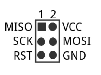
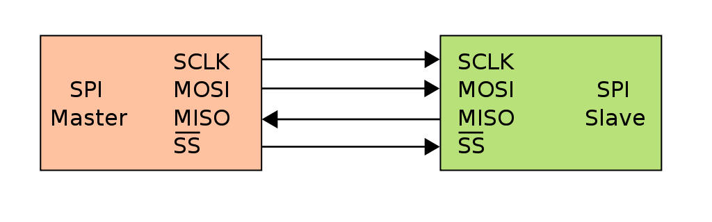
The Attiny's chip can be programmed using In-System-Programming (ISP), a very simple and efficient way of programming a system using an external programmer. There are plenty of programmer able to do ISP programming on the market, the Atmel-ICE for exemple, is a great tool to have for any hobbyist that has to work with modern micro-controllers. But one that we absolutely love (and hate) in the Fablabs environement is the famous fabisp . The chip and the programmer exchange information using a serial peripheral interface (SPI).
The EchoTiny
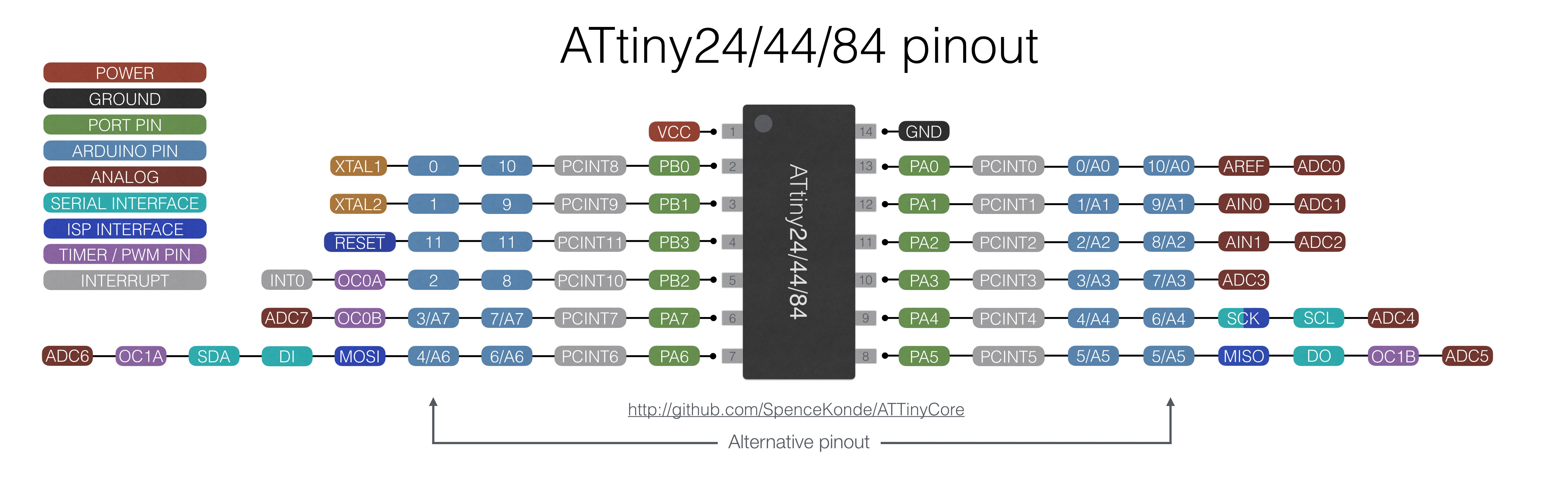
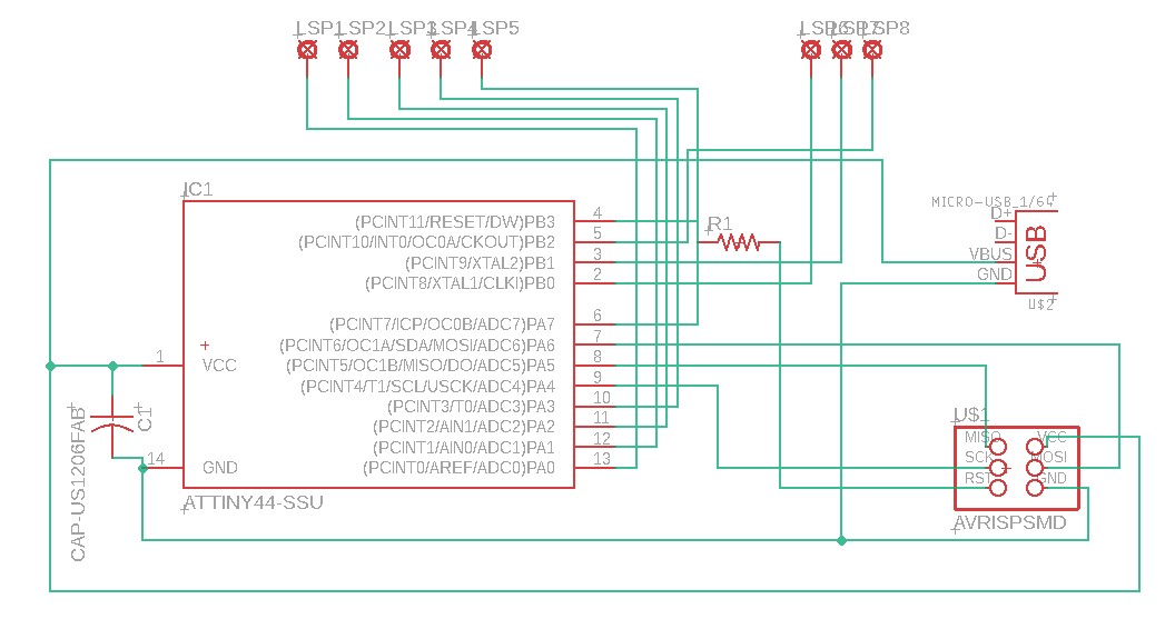
I used eagle to draw my schematic, it is a very simple board consisting of an ATtiny44, a resistor, an ISP header, a resistor, an usb outlet and a capacitor.
I used a 100uF capacitor between the VCC and GND pin to stabilise the current flow. This is a common method call decoupling and it make sure that voltage spike does not interfere with our system. It is nothing else than a safety measure.
The 10k resistor between the reset pins serve as a barrier to make sure that the pin is not floating while not being sollicitated.
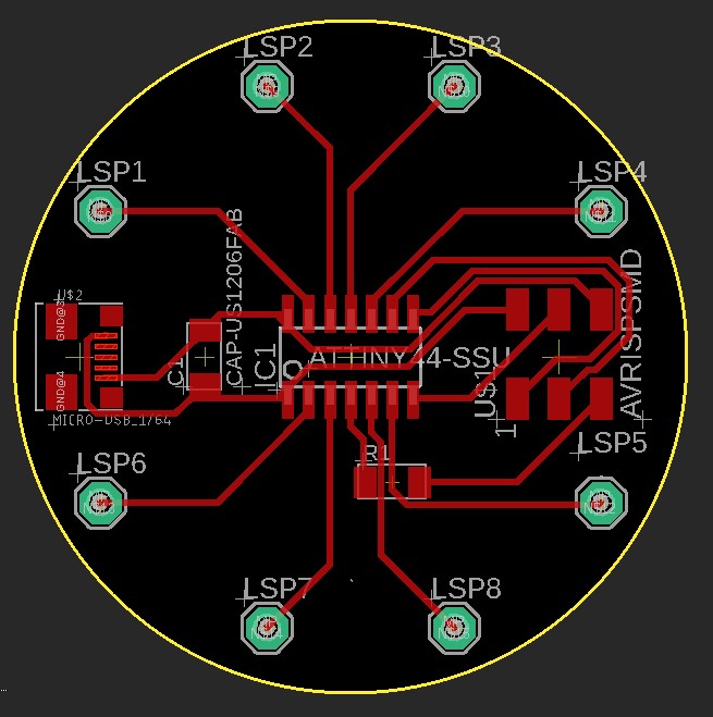
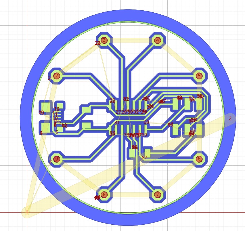
I did the routing using 15 thousand of an inch traces, this is a bit sketchy since I intend to mill this pcb, I will have to make sure that the cnc is well callibrated and ready to do precision work, but I really want to keep the design small and compact, and don't want to do two layer pcb since the goal is to make the board as easy and reproductible as possible.
All I had left to do was machine the board, to do so I use my 2x3' cnc and double sided tape to fix the copper sheet onto the sacrificial bed. The milling went great using my 0.1mm v-bit. Here are some demonstration.
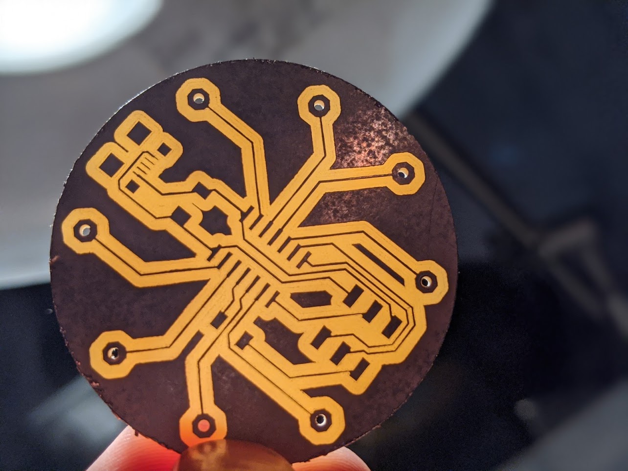
As you can see in my video, I totally forgot to create a ground and VCC pin output, this mean that I had to solder a jumper wire directly on the Attiny44 pin wich is far from being optimal. I will have to do a second iteration of the circuit with that in mind, but we can still see that the circuit is working and programmable. Nice!
Building a heatpad
To transform electric current into heat, all you really need is a resistor. The energy that flow trought the resistor transform itself into heat. This is what we call the principle of Joule heating. So yes... every electric heater that you have, from your toaster to your calorifier is basicly just a big old resistor!
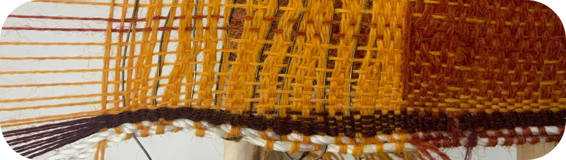
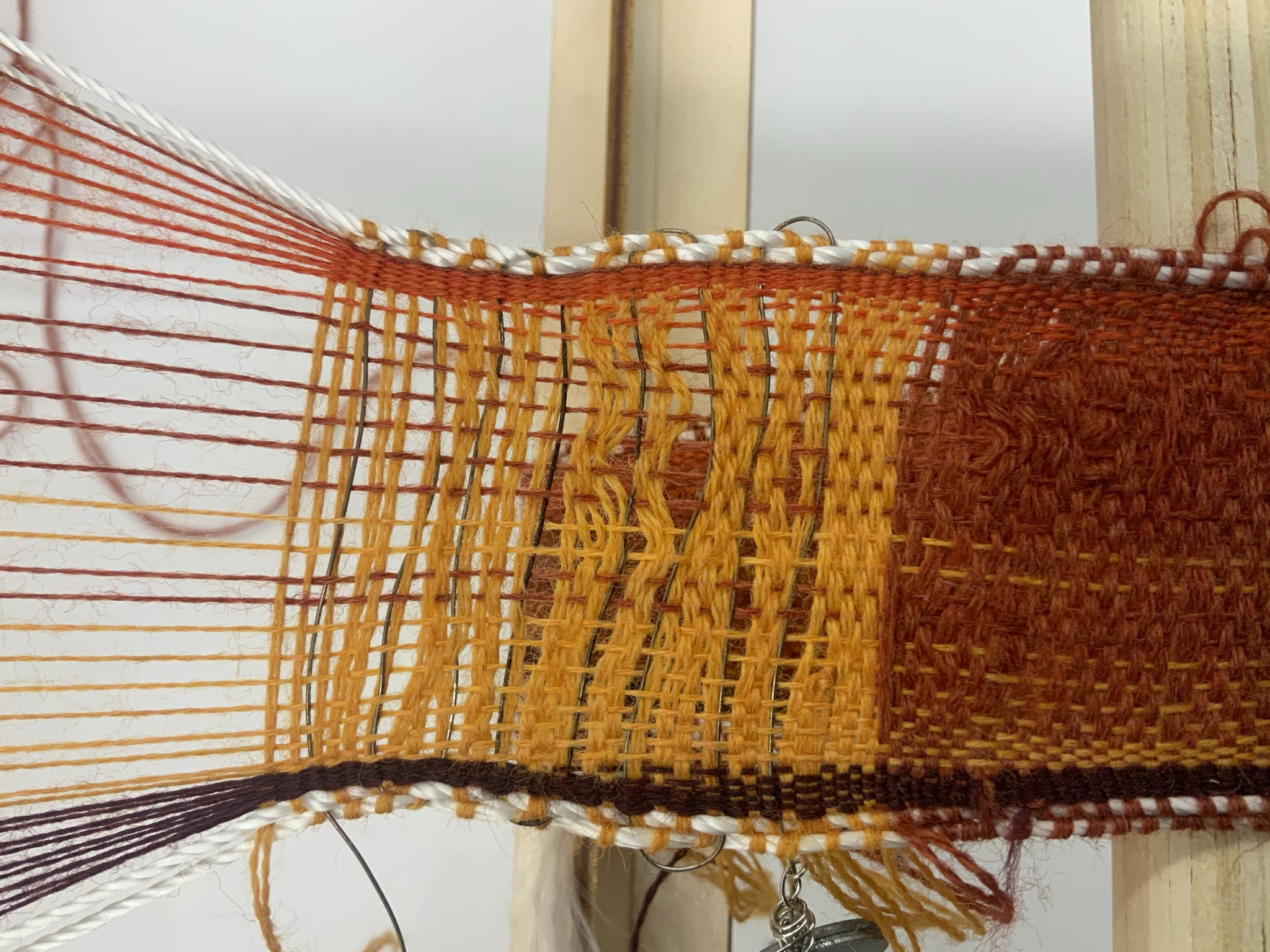
This week I learn that a very comon material use to create heat out of an electric current is Nichrome. Nichrome is an alloy compose of Nickel, Chromium and Iron. It can be easily find on the market and is pretty cheap. Noemie and me decided to make a small test using a Nichrome wire that we weave using our weaver that we made few weeks back!
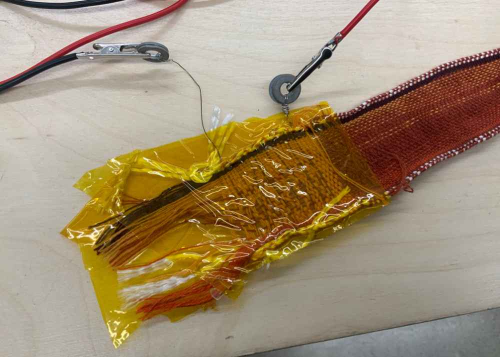
To make sure that the fibers in between the Nichrome wouldn't burn or take fire, we use polyimide tape, commonly known as Kapton. This heat resistant tape is perfect for absorbing the heat that will be generated from the nichrome wire. Please bare in mind this is only a prototype and is not supposed to look good in any way!
Programming an ATtiny
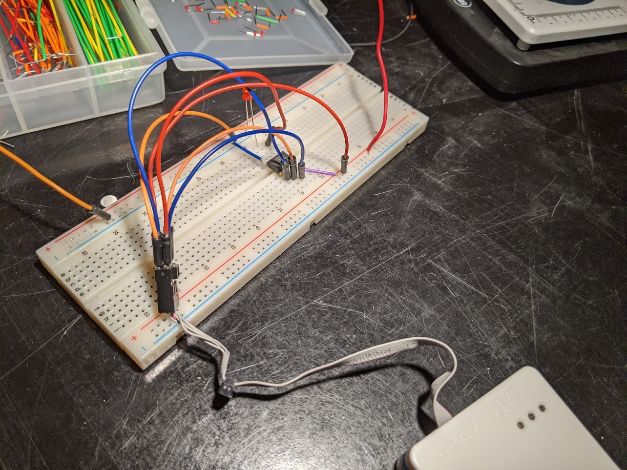
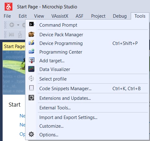
Once everything is wired up, we can go ahead and open Atmel Studio (wich is now named Microchip Studio). Inside Atmel Studio, we can open the device programming interface. And select our programmer and the chip that we want to program, If everything is wired correctly you should see a red and a green light on the atmel ICE, don't forget to power your attiny from an external source.
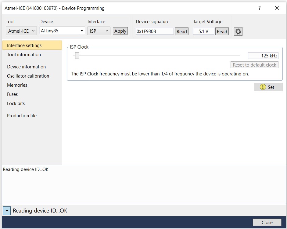
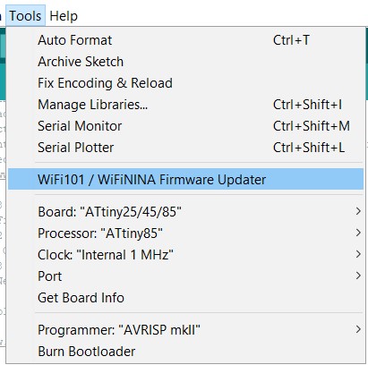
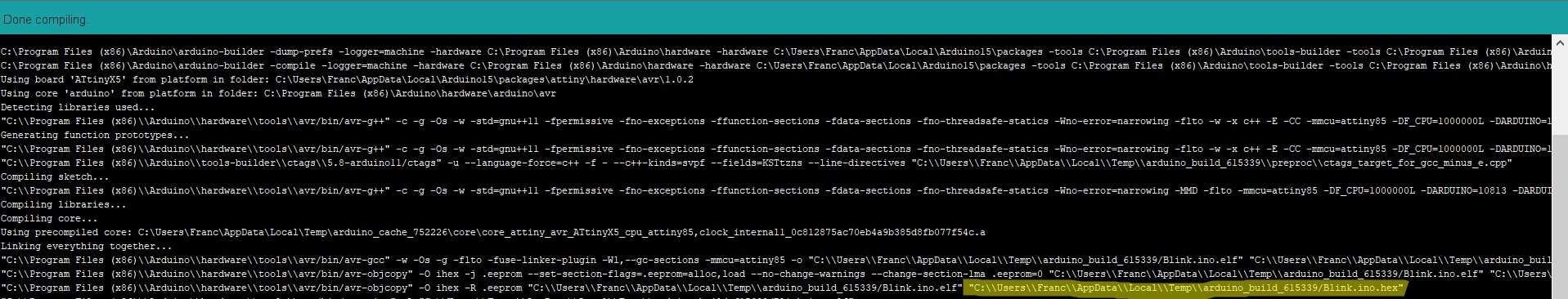
One the device signature is able to be read, we should be good to go. Atmel Studio is able to read arduino code. When you compile an arduino code, if you activate the verbose for the compiling, you should see the temporary folder in wich the compilation is set. you are looking for a .hex file. You have to keep in mind that before compiling, you have to set your board as an Attiny85 and use the internal 1Mhz crystal for the clock. To install the Attinys into your board collection on the arduino IDE you can follow this tutorial.
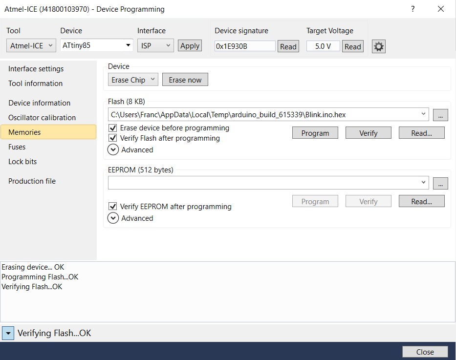
Then you can go into the memories tab and flash your code into the ATtiny, If everything is wired up correctly, you should see a LED blink!
Prototyping my final project
Since I alredy know a lot about the Arduino Architecture, I decided to switch my initial idea of using the Flora to an arduino Uno, it will also give me the possibility to connect my motor,sensors,output alltogether. For more information on this you can visite my final project page.
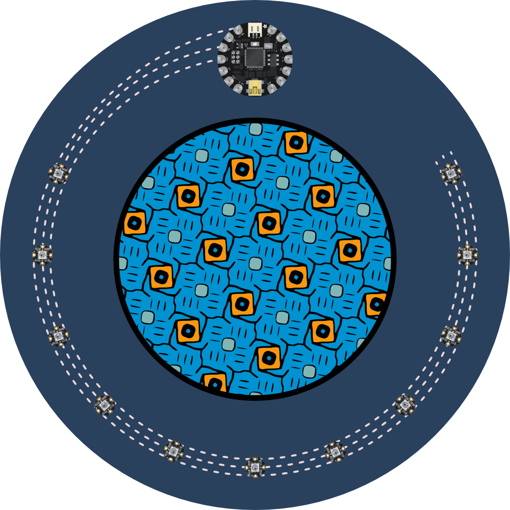
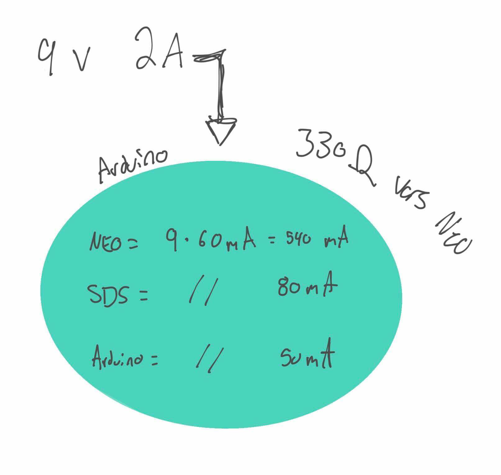
Each Neopixel can draw a maximum current of 60mA. An arduino Uno is capable of outputing up to 900mA trough it 5V pin using an external powersupply (since it is not connected directly to the MCU). It is also important to note that you can't output more than 40mA per logic pin and that the Arduino in itself draw around 50mA.
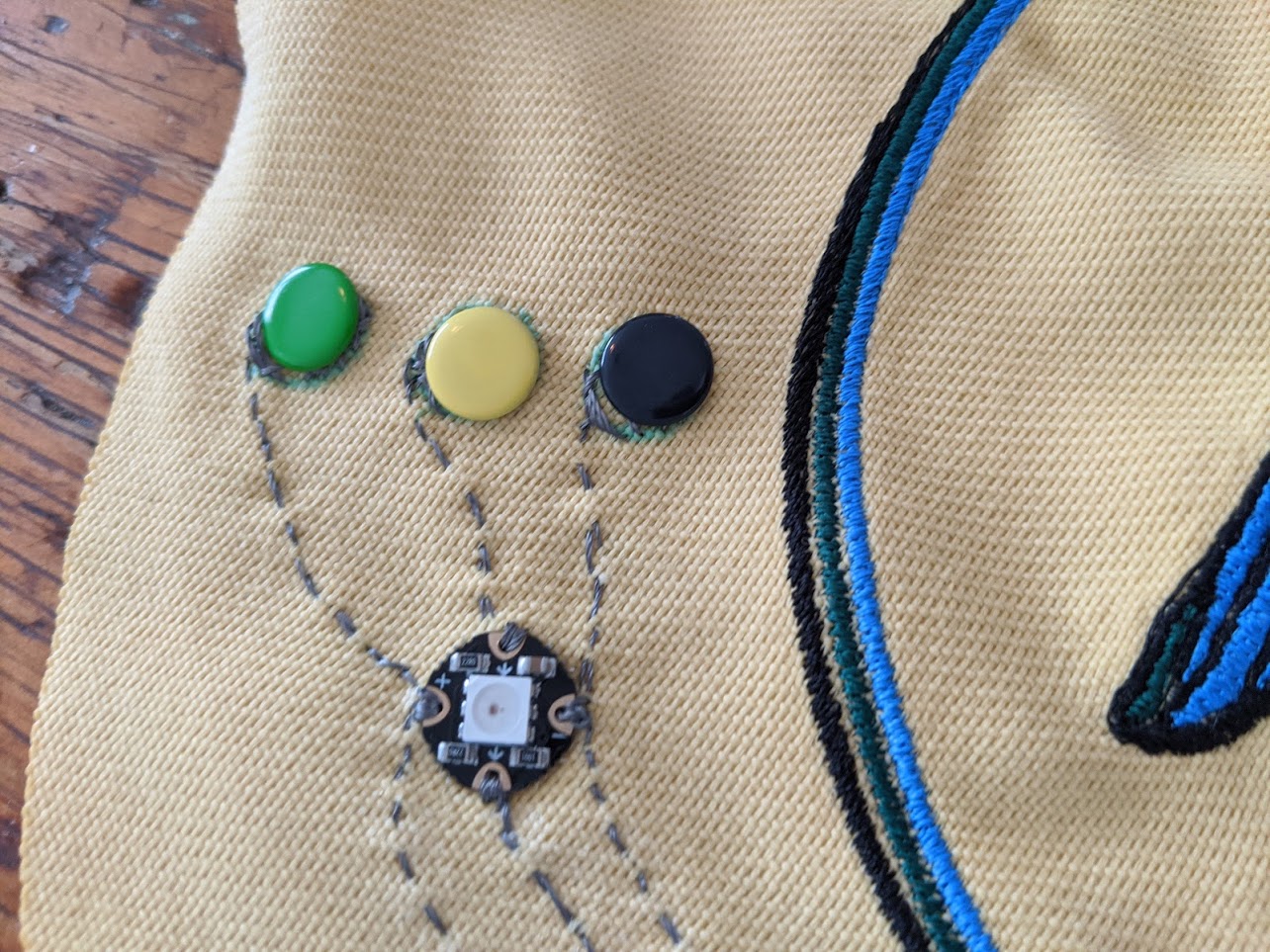
For my connector, I used those very cute and pratical rivet pins that gives me the ability to snap and unsnap my connection. I can even color code everythin to make things easy.
To program the neo pixel, I used the official Neopixel Arduino library provided by Adafruit wich is pretty easy to use and has a bunch of documentation here. You can find pretty much everything you need to know on there to program and have fun with your neopixels. Refer to my final project page for more information but here is the code for the whole system: