5. E-Textiles
The E-Textiles week was the first week as a student of the Fabricademy. I am still so overwhelmed by all the information, tutorials etc. Unfortunately I couldn't be there from the beginning and couldn't watch the tutorials and lectures live, but I'm going to make up for everything now and I'm really looking forward to the following soft robotics and skin electronics lessons! So, let's go!
Liza Stark has given us really great inputs in her lecture
Important units and formulas
Voltage - Volt - V: Electrical Pressure or Force between two points
Current - Amps - I: Rate at which electric charge flows
Resistance - Ohms - R: the amount of material that resists the flow of current
TADAAAAAAAAAA: Ohm's law - V=IxR (or as we call the formula in Austria: U=RxI)
Rule 1: Electrons are lazy
Electrical energy always follows the path of least resistance to ground.
ATTENTION: Watch out for windy traces or short circuits.
Rule 2: Electricity hates waste
All electrical energy in the circuit must be used.
ATTENTION: Otherwise it will dissipate as heat and possibly damage your components.
Rule 3: Circuits are a system
Different components play a different role in the system of the circuit
ATTENTION: you need to know which components you need and how you should arrange them.
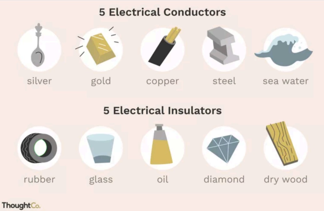
Conductive Materials
Conductive Material I bought:
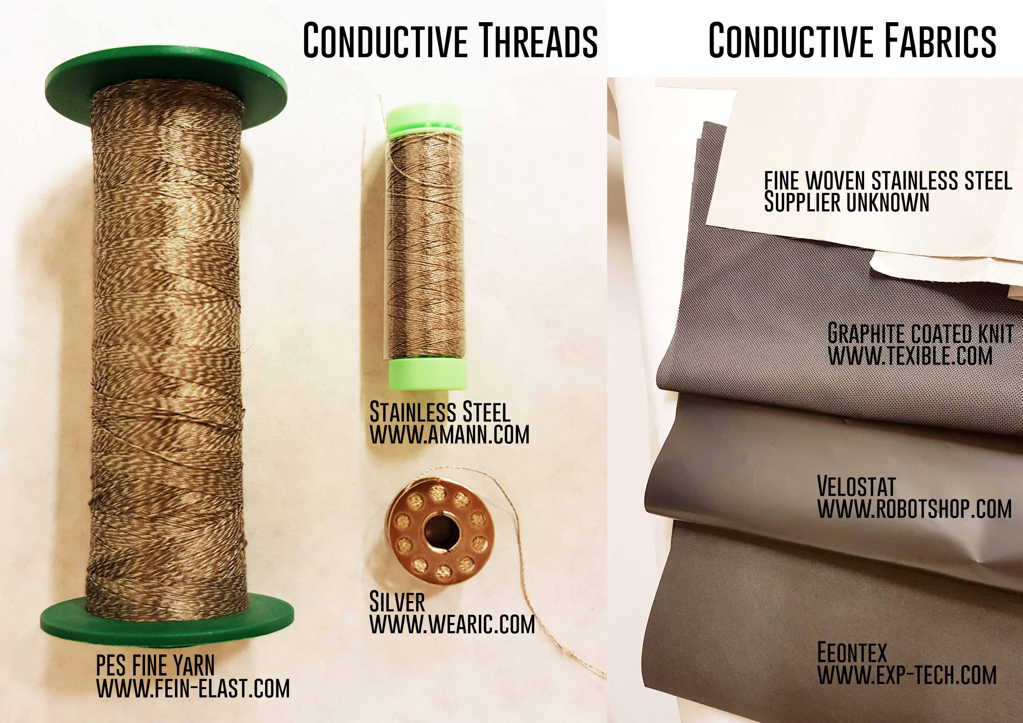
EeonTex (ordered at exp-tech.com)
This EeonTex fabric is a conductive and non-woven microfiber for use in e-textiles. thickness: 0.8 mm. EeonTex Conductive Fabric is highly conductive with a surface resistance of 8 Ohm / sq to 105 Ohm / sq. It is also extremely durable with a tensile strength of > 450N and a tear strength of 12N.
Velostat (ordered at Robotshop.com)
The Pressure-Sensitive Conductive Sheet: squeezing it will reduce the resistance, so it's handy for making flexible sensors. And it's a lot less expensive than off-the-shelf pressure or bend sensors too! To remove any hard creases, simply lay flat on a table and put a heavy book on top to flatten it out.
Specifications
- Dimensions: 11" x 11" (280mm x 280mm) 4 mil / 0.1mm thick
- weight: 18.66g
- Temperature Limits : -45°C to 65°C (-50°F to 150°F)
- Heat Sealable : Yes
- Volume Resistivity : <500 ohm-cm
- Surface Resistivity : < 31,000 ohms/sq.cm
Other materials I have found in our coworking company:
- Graphite coated knitwear - self-made
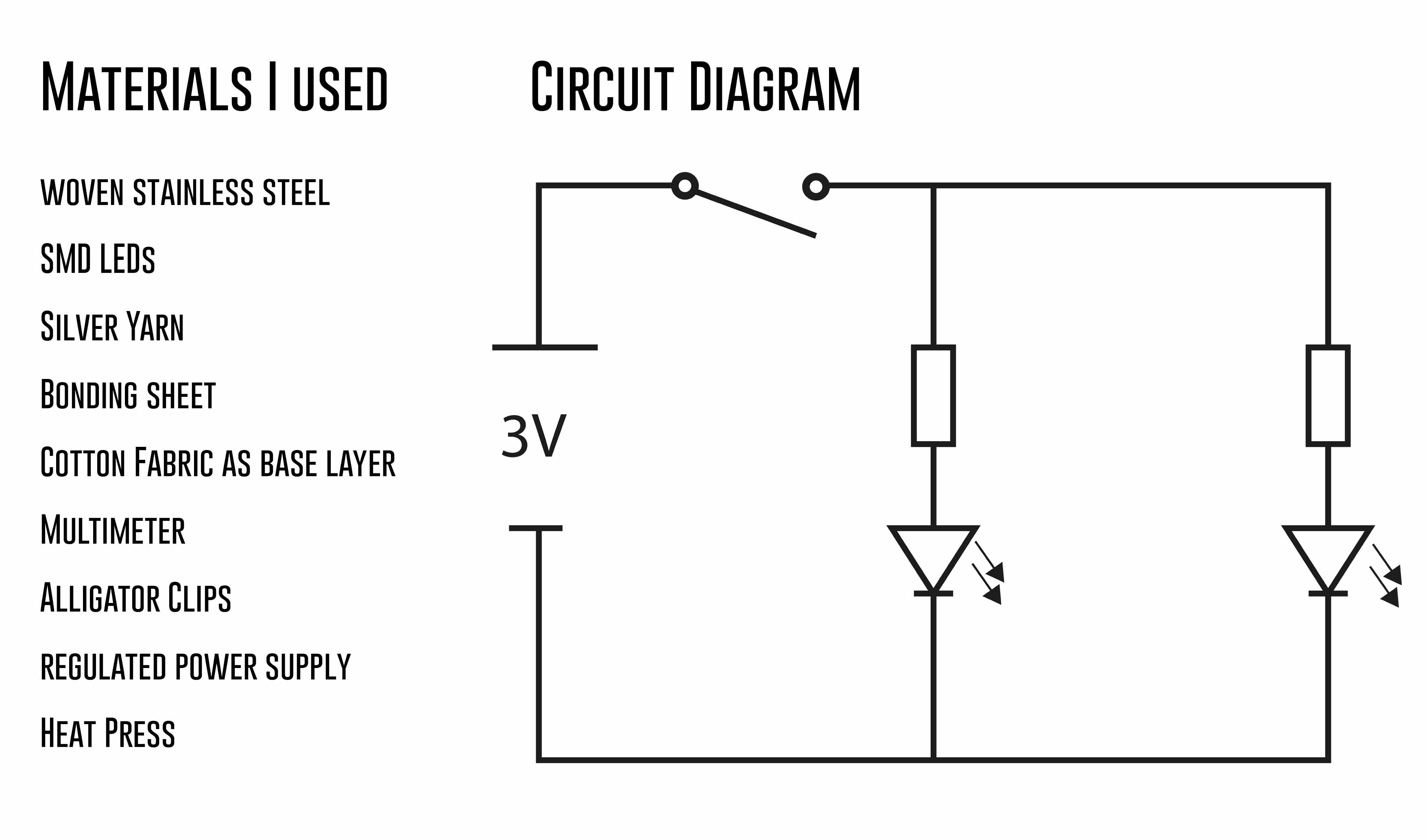
- fine woven stainless steel - manufacturer unknown
Conductive yarns I have at my disposal:
- Stainless steel yarn
- Polyester fine yarn
- Silver Yarn
Digital or Analog Inputs
Inputs is information or data that enters a system, like a button press.
What's the difference?
Digital:
Switches
ON/OFF
011011011 etc.
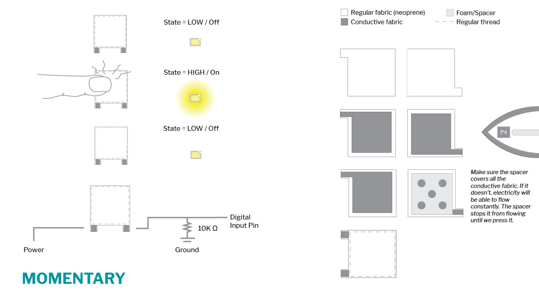
A switch is a break in a circuit! Since the circuit is not complete, no electricity can flow to the components.
Momentary Switches (Push Buttons) stay open as long as you hold them by pressing conductive materials into contact.
Analog:
Sensors
Range of Values
1023, 521, 34....
All values between the minimum and maximum.
If it is an electric signal:
Minimum: GND
Maximum: VCC
If it is a sensor:
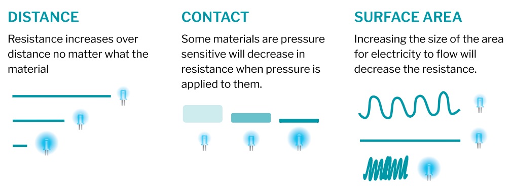
Variable Resistor!!!!!
We can use resistance to get a broader range of values. By allowing more current to get through you can change the brightness of an LED, the frequence of a sound, the speed of a motor. by varying resistance of the input, I can change the output. That is why they are also called variable resistors.
Starting Emma Pareschi's first tutorial
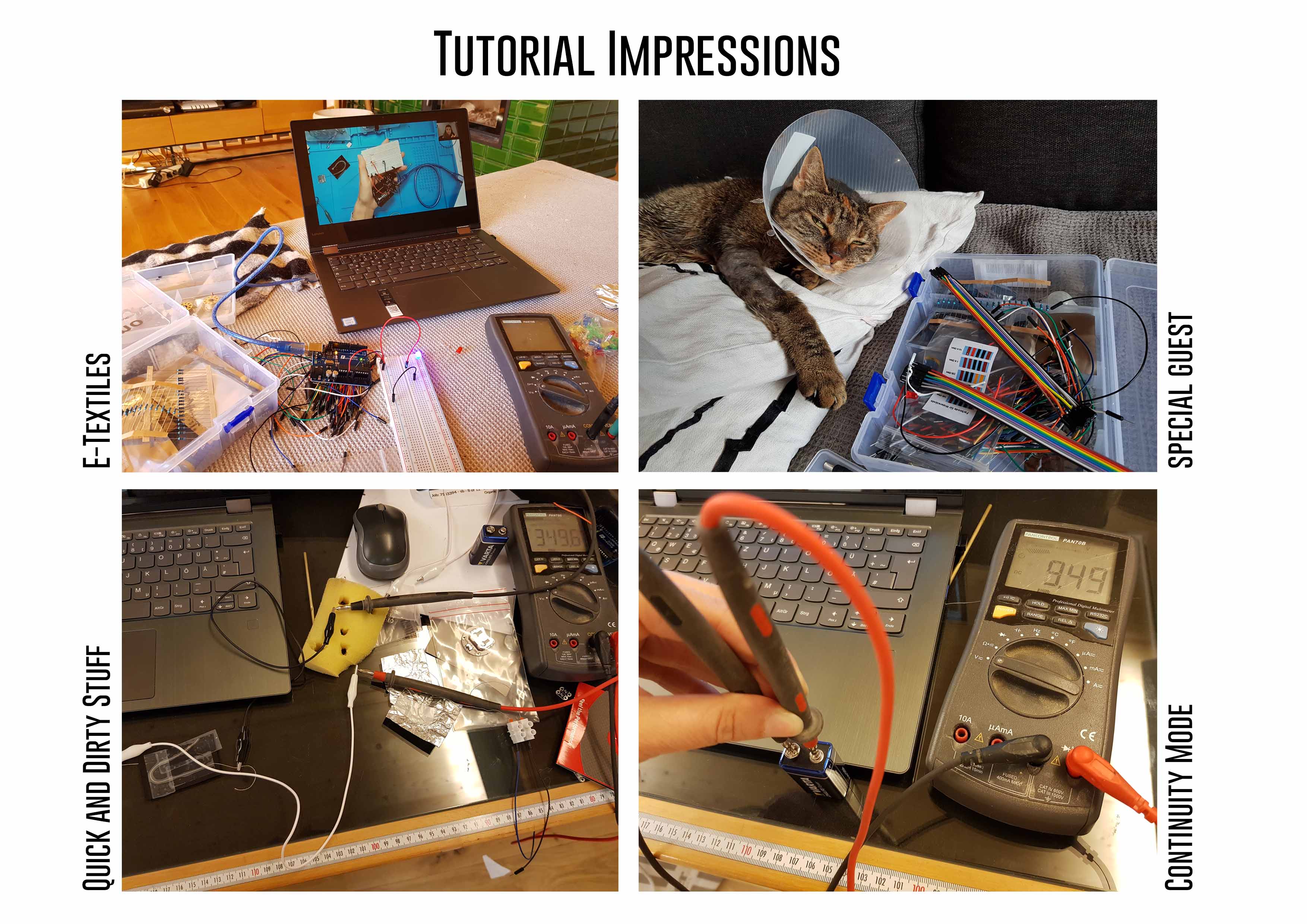
Working with the multimeter:
Measuring different Voltages on different batteries:
in my case I have tested a 9V battery.
Voltage at the multimeter: 9,49 V
The 3V coin cell battery says: 3,266 V
This is normal because the batteries do not have a nominal value (due to chemical reactions)
Continuity Mode at the multimeter:
you can use the continuity mode for testing if a material is conductive!
Continuity testing is the act of testing the resistance between two points. If there is very low resistance (less than a few Ωs), the two points are connected electrically, and a tone is emitted. If there is more than a few Ωs of resistance, than the circuit is open, and no tone is emitted. This test helps insure that connections are made correctly between two points. This test also helps us detect if two points are connected that should not be. Continuity is quite possibly the single most important function for embedded hardware gurus. This feature allows us to test for conductivity of materials and to trace where electrical connections have been made or not made. Set the multimeter to 'Continuity' mode. It may vary among DMMs, but look for a diode symbol with propagation waves around it (like sound coming from a speaker). Extracted from [Sparkfun](https://learn.sparkfun.com/tutorials/how-to-use-a-multimeter/continuity)
A Circuit:
What you need:
- source of electrons
- material to let the electrons flow
- a load (resistor, lights, heating elements, motors etc. to avoid short circuits)
Power Supply (LED+Resistor) in a circuit:
- Battery: 9V => R > 470 Ohm
- Battery: 5V => R > 220 Ohm
- Battery: 3V => no Resistor
Assignment Digital Sensor
A few weeks ago I bought a fabric sample with a digital print of Jeanne D'Arc in her armor. So I knew: I had to do something with this fabric sample and I decided to make a digital sensor: a momentary switch.
I want Jeanne D'Arc's eyes to glow as soon as I touch her armor. And I made this....
FOCUS: The momentary switch was planned to be simple but clean!

Challenges
- Working with different conductive materials and the associated different processing. - to focus the light diffusion of the LEDs on the eyes of Jeanne d'arc. - to place the LED's precisely (and thus the precise planning and implementation of the schematic), as well as to prevent the LED's from slipping by using Bemis Bonds. - The layers of the materials should be such that no interfering connections or components are visible either from the front or the back. - It should be an attractive design that can be easily integrated into everyday objects.
First Steps
The first steps were very, very dirty:
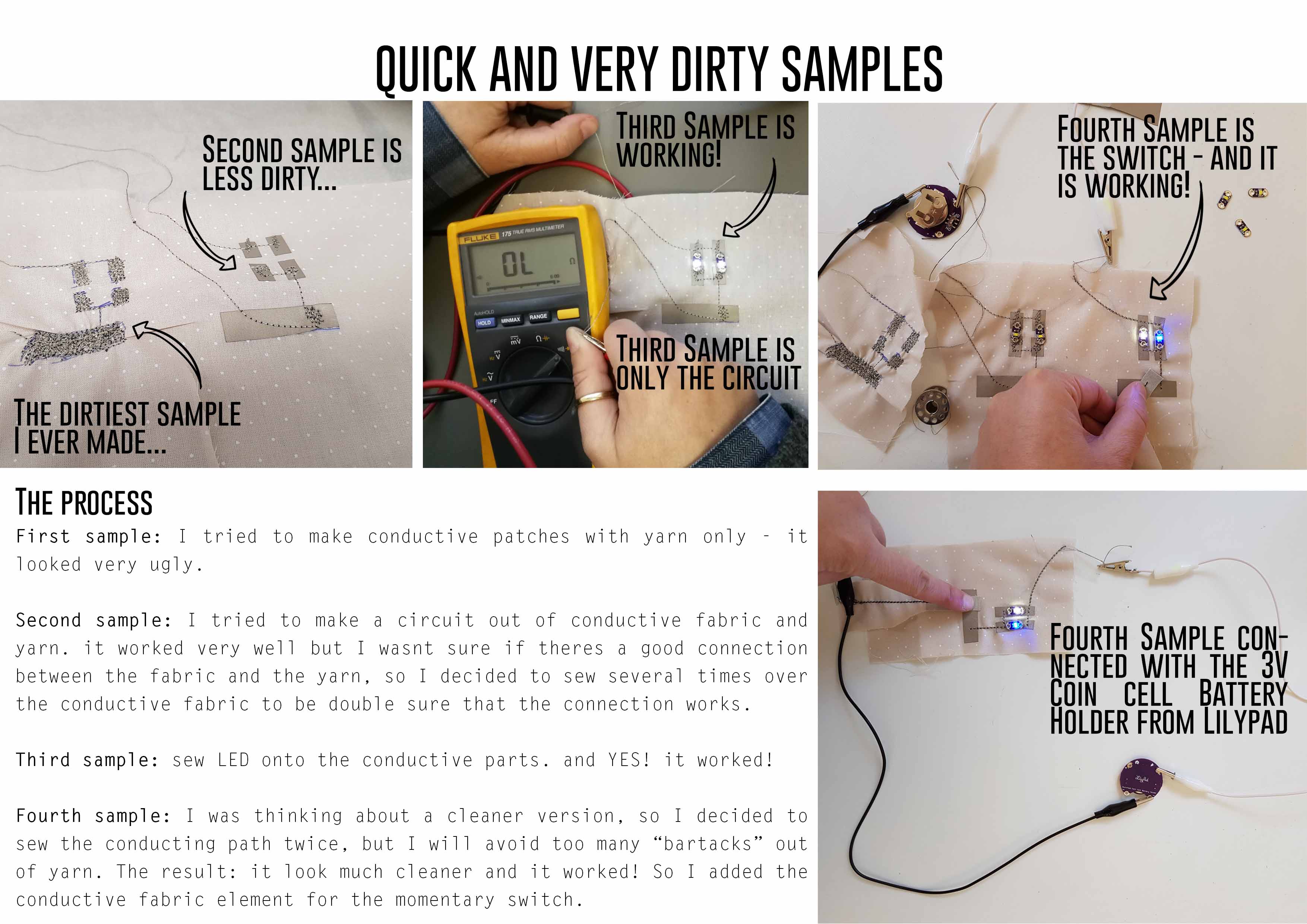
BUT!!! because of the dirty samples i could improve the schematic and came to this result:
This is how I made the momentary switch:
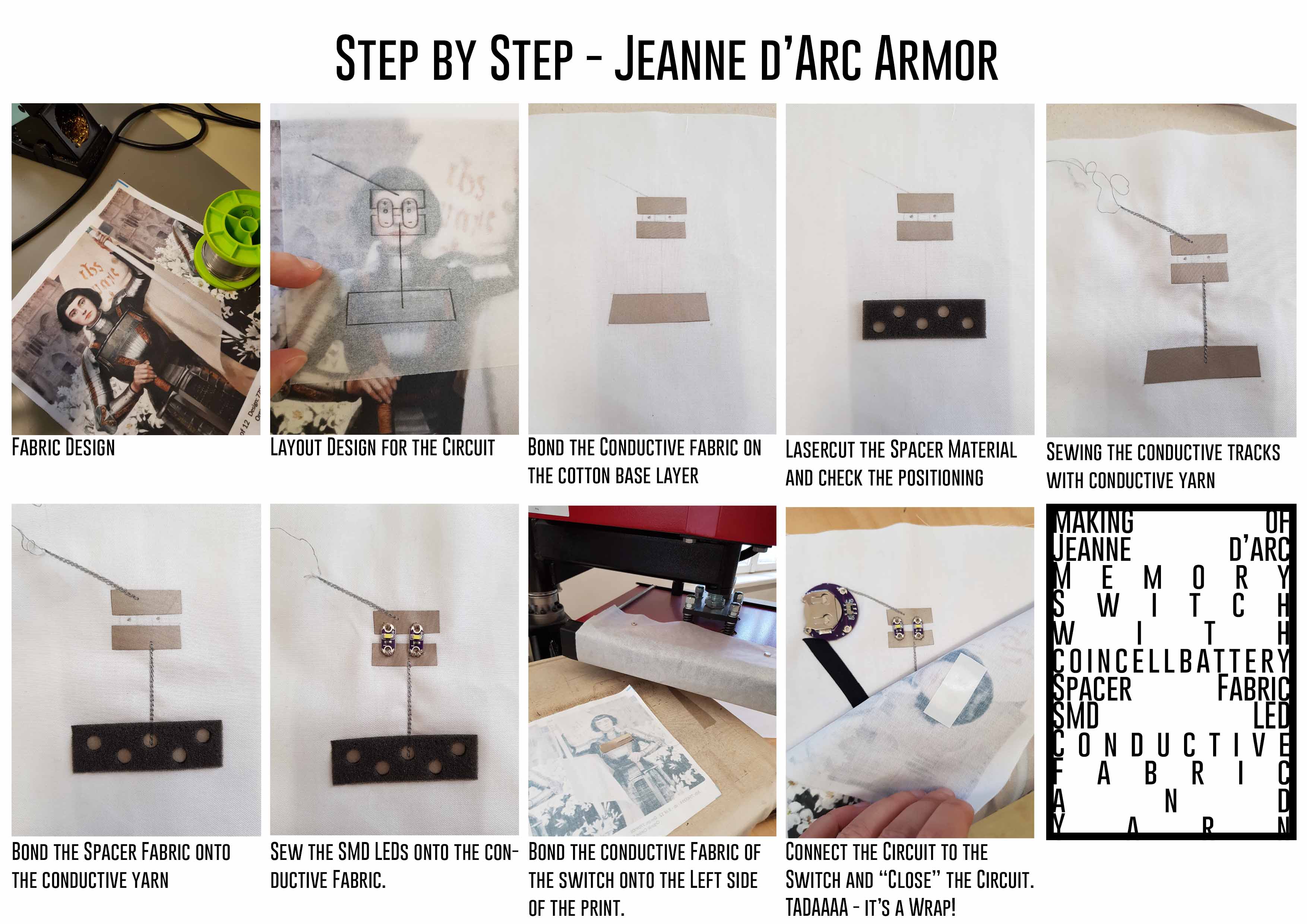
LASERCUT ACTION
I actually wanted to lasercut her eyes, but when I tested it on a piece of fabric, I realized that it didn't look good at all. So I only lasercut the spacer fabric with 5 holes for the switch.
Settings of the lasercutter:
Speed: 80
Max. Power: 75
Min. Power: 70
Final result
The momentary switch is constructed very clean and soft. You can squeeze it in your clenched fist and the sensor is immediately functional again. Finally you can see the result here:

Assignment Analog Sensor
details will be filled in later...