12. Skin Electronics
Research


Skin electronics represent a new frontier in wearable technologies, focusing on flexible, stretchable, and ultra-thin electronic devices that can interface directly with human skin. These devices are designed to monitor biometric signals, sense environmental changes, and provide interactive capabilities without compromising comfort or skin integrity.
The development of skin electronics combines material science, electrical engineering, and biocompatible design to create systems that can stretch, bend, and conform to the complex surfaces of the body. Common applications include health monitoring, physiological tracking, temporary tattoos with sensing functionality, and interactive biowear.
- NeoTouch
- Skin Electronics by Carlotta Premazzi, made with Eden.art
get inspired
-
Skin Circuit - Grecia Bello - Fab Lab BCN
-
Interactive glove - Asli Aksan - Textile Lab Amsterdam
-
Face Mask - Riley Cox - Textile Lab Amsterdam
-
Skin electronics research - Julija Karas - Fab Lab BCN
On-body Technologies & Skin Interfaces
Wearables already extend the body — they add functions, collect data, amplify our abilities, and create a bridge between our physical presence and the digital world. But even as extensions, they remain external objects, something we strap on, attach, or carry.
Skin electronics goes a step further: it dissolves this separation. Instead of placing technology on the body, it embeds it into the surface of the body, becoming thin, flexible, and almost invisible — like a second skin. It transforms the skin into an active interface, where sensing, communication, and expression happen directly on the body’s surface.

This shift moves us from devices that extend us from the outside to technologies that feel organic, adaptive, and intimately connected (but not invasive), reshaping how we experience and interact with the world.
Multiple layers of wearable placement, from extern to intern:
- Carried-on (external)
- On-body(wearables)
- Skin interfaces (directly on the skin).
- Inside-body (implants)
On body tecnhologies Illustration by Carlotta Premazzi
The Skin as an Interface
 Skin Proprieties
The human skin constitutes a primary biological interface between the body and the environment. It performs multiple fundamental functions: as a filter, it regulates the exchange of substances, protects against external agents, and maintains homeostasis; as a sensor, it perceives mechanical, thermal, chemical, and nociceptive stimuli; and as an actuator, it mediates physiological responses such as thermoregulation, secretion, and micro-motor reflexes.
Advances in skin-integrated technologies extend these inherent capabilities, transforming the skin into a dynamic technological interface. Through the integration of flexible sensors, actuators, and electronics, the skin can serve as both an input and output platform, capable of detecting biological, chemical, or environmental parameters and conveying them through visual, tactile, or other perceivable signals.
Roles and Potential of the Skin as an Interface
| Role / Function | Description |
|---|---|
| Natural Filter | Protects the body from substances, light, microbes, and temperature. Selects what enters and exits, creating an active barrier. |
| Biological and Tactile Sensor | Detects pressure, vibration, heat, pain, texture, touch, and humidity. Acts as our primary channel of input from the environment. |
| Body Actuator | Responds with sweat, contractions, redness, hair erection, or secretions. Translates stimuli into actions or perceivable signals. |
| Extended Technological Output | Through skin electronics, the skin can emit light, color, vibrations, or other perceivable information. Converts invisible signals into experiences perceptible to ourselves or others. |
| Enhanced Natural Input | Can sense chemical, biological, or metabolic parameters, connected to digital systems or AI. |
| Communication and Social Channel | Can display information or internal states discreetly, visible only to those who can interpret it. |
| Extension of Bodily Capabilities | Turns the body into an active tool for monitoring, interacting with smart environments, or controlling external devices. |
By conceptualizing the skin as an organ of interaction augmented by technology, we establish a framework for human–device symbiosis, where the body itself functions as a responsive, adaptive, and communicative interface. This perspective provides a foundation for research in wearable computing, interactive cosmetics, bioelectronics, and human-centered design, highlighting the potential for seamless integration of technology with the human body.
Important considerations for skin (extended/augmented) interfaces:
- Body movement
- Skin type (dry, oily, sensitive)
- Attachment and adhesion
- Weight and insulation
- Aesthetics
- Conductive materials and durability
Beauty Technology
Beauty Technology, as introduced by Katia Vega, defines a subfield of wearable computing in which technological components are embedded within cosmetic products applied to the body. Through this approach, the human surface becomes an interactive interface, where skin, hair, and nails are transformed into active technological platforms capable of sensing, signaling, and mediating interactions.
A new subfief in wearables computing that throug provocative design extends the horizon of expectation of Human-Device Symbiosis Transform traditional to INTERACTIVE COSMETICS in order to use the SKIN AS INTERFACE. Unnotice wearable devices that CAMOUFLAGE ELECTRONICS within cosmetics and CONCEAL INTERACTIONS by using human behaviors.
It marks a shift: from visible wearables → to invisible, body-integrated aesthetics.
Key aspects:
- Invisible interfaces
- Camouflaged Electronics/devices
- Natural behaviors as input (blinking, smiling, hair touching)
- Discreet and invisible interactions
- Human–device symbiosis
- Applications in art, medicine, fashion, performance
Skin as Display
If Beauty Technology refers to electronics embedded into cosmetics for interactive and aesthetic purposes, Biocosmetic Interfaces focus on discreet, non-invasive health monitoring through cosmetics. These include makeup, patches, or nail products with properties that can be analyzed via apps and AI to provide real-time metabolic or physiological feedback. They are usually temporary and applied externally, like colorimetric pH cosmetics.
In contrast, Body Modification Technologies involve semi-permanent or permanent interventions that integrate with the body, such as tattoos, piercings, or implanted biosensors. These technologies directly interface with bodily fluids or internal signals, transforming the skin into a bio-display. The focus is on biofeedback, monitoring, and data visualization rather than purely aesthetic interaction.
Dermal Abyss: Tattoos that change color through:
- Biosensors
- Fluorescent inks
- Chemical reactions
Applications:
- Health monitoring
- Metabolic feedback
- Real-time body data visualization
The skin becomes a biological display.
Main Projects
| Project | Category | Description | Key Features / Examples | Goal |
|---|---|---|---|---|
| Sweatcessory | Biocosmetic Interfaces | Wearable necklace with sweat biosensor for real-time monitoring. | • Electrochemical sensors • Detects sodium and other analytes • Bluetooth-connected app for visualization |
Enable non-invasive physiological monitoring through wearable jewelry. |
| Colorimetric pH Cosmetics / Skin Patches | Biocosmetic Interfaces | Temporary makeup or patches that change color based on skin pH or other metabolic markers. | • Disposable or single-use products • Colorimetric response readable via app • Non-invasive |
Provide real-time feedback on skin or metabolic status with temporary, applied cosmetics. |
| Dermal Abyss | Body Modification Technologies | Tattoos that change color based on biochemical signals in the skin. | • Biosensors integrated into tattoo ink • Fluorescent or colorimetric inks • Monitors sodium, glucose, pH |
Transform skin into a biological display for health monitoring and metabolic feedback. |
| BraceIO | Skin Electronics / Beauty Technology | Orthodontic ligatures that change color depending on saliva composition. | • Hydrogel-based ligatures • Measures pH, nitric oxide, uric acid • Readable via external device |
Create interactive biosensors embedded in dental appliances. |
| Hairware – Conductive Hair | Skin Electronics / Beauty Technology | Hair or extensions become capacitive sensors. | • Chemically metallized strands • Detects touch along root → tip • Up to 92% gesture accuracy • Triggers digital/physical actions |
Turn hair into an interactive input device. |
| Conductive Makeup – The Face as Interface | Skin Electronics / Beauty Technology | Makeup acts as an invisible technological layer on the skin. | • Blinklifier – blink-triggered interaction • Winkymote – IR remote control via blinking • Kinisi – expression-based controls |
Makeup becomes an invisible wearable interface. |
| TechNails – Interactive Nails | Skin Electronics / Beauty Technology | Nails serve as hosts for micro-interactive components. | • NFC/RFID tags • LEDs • Sensors • Projects: Twinkle Nails, Gimmickiano, AquaDJing |
Nails as micro-interaction platforms. |
| FX e-Makeup | Skin Electronics / Beauty Technology | Prosthetic cosmetic effects with embedded electronics. | • LED/Neopixel integration • Motion or touch-responsive • Can be applied to face or body prosthetics |
Enable interactive theatrical and performance effects. |
pHigment: Biodegradable Single-Use Cosmetics for On-body Chemical Sensing
The pHigment project, developed by the Interactive Organisms Lab (led by Dr. Katia Vega), explores a novel approach at the intersection of body-worn interfaces, chemistry, and sustainability. The goal is to replace existing single-use makeup products with biodegradable, colorimetric biosensing materials.
Project Overview and Dual Objective
The pHigment project tackles a dual objective: designing interfaces that are environmentally sustainable while also enabling on-body chemical sensing. The prototypes act as colorimetric biosensors, reacting visibly to pH changes and providing potential insights into dental health, vaginal chemistry, and skin surface conditions. At the same time, the project focuses on single-use cosmetics—such as temporary tattoos, eyeliner stickers, and press-on nails—to replace traditional synthetic materials, which often end up in landfills, with compostable and biodegradable alternatives. Through this approach, the project demonstrates how ephemeral beauty products can function simultaneously as responsive chemical sensors and sustainable wearable devices, redefining the relationship between cosmetics, technology, and environmental responsibility.
 The pHigment prototypes rely on a safe, fully biodegradable fabrication method based on alginate formulations.
Fabrication Process
- Mixing water, red cabbage powder, titanium dioxide, glycerin, and sodium alginate.
- Casting the mixture into molds or thin layers.
- Treating it with a Calcium Chloride solution to polymerize the alginate.
- Drying the material to obtain thin, flexible cosmetic forms such as stickers or patches.
The result is a set of biodegradable, color-changing, skin-safe cosmetic devices that function as wearable chemical sensors.


Ph patch preparation and BIO-ALG-RCP-FILM-PH-001 sheet by Carlotta Premazzi
tools
- Immersion Blender
- Scale
- Glass Jar (that will fit in the vacuum chamber)
- Cameo
- Vacuum Chamber
- Double-sided Sticky Paper
- Disposable Boats (2-3)
- Tracing Paper
- Scissors
- Long Small Spoon
- Spray Bottle
- Plastic spreader or any straight and flat object to be used as such
- Acrylic Sheet or Metal Oven-safe tray
Ingredients
- 10 g calcium chloride
-
100 g water
-
100 g Water
- 0.25 g Red Cabbage Powder
- 0.1 g Titanium Dioxide
- 5 g Glycerine
- 2.5 g Sunflower Oil
- 3 g Sodium Alginate
Recipes
To Make the Calcium Chloride Solution
1. Heat 100 g of water until hot, either on the stove or in a kettle.
2. Stir in 10 g of calcium chloride until dissolved.
3. Pour into a spray bottle and let cool completely.
- This solution can be stored and reused for multiple batches of biomaterial.
To Make the Biomaterial
1. Put the glass jar on the scale and tare it to zero.
2. Measure 100 g of water into the jar.
3. Measure the remaining ingredients in order, mixing with a clean spoon between additions:
- 0.25 g red cabbage powder on tracing paper, pour into jar
- 0.1 g titanium dioxide on tracing paper, pour into jar
- 2.5 g sunflower oil into a boat, pour into jar
- 5 g glycerine into a boat, pour into jar
4. Measure 3 g sodium alginate into a boat and add slowly while mixing with the immersion blender:
- Add very small spoonfuls to prevent clumping
- Can split into thirds or smaller portions (e.g., 10ths) for a smoother mixture
- Mix with the immersion blender on high until fully combined and smooth
Using the Vacuum Chamber 1. Place the jar (without lid) in the center of the chamber; tape it down if needed. 2. Close the lid and ensure the plug is tight. 3. Press "on" and select AI to set the timer to 15 minutes. 4. Watch for bubbling; pause if necessary. 5. Depressurize slowly after completion. 6. Scoop any clumps and gently stir with a spoon.
Pouring and Drying the Biomaterial
1. Prepare a flat surface for drying:
- Acrylic sheet or smooth non-stick surface for air drying (7 days or 3 warm sun days)
- Metal tray for oven/convection drying at 120-140 °F (~2 hours)
2. Pour biomaterial onto the surface and spread thin using a smoothing tool.
3. Shake Calcium Chloride solution and mist from ~1 foot away.
4. Let sit 5-10 minutes, material will shrink and edges lighten.
5. Respray edges and allow to dry completely.
6. Final product should be paper-like, smooth, face mask consistency.
7. Peel biomaterial carefully off the surface.
Cutting the Biomaterial
1. Prepare double-sided sticky paper.
2. Cut a rectangle of desired size.
3. Peel one side to expose adhesive.
4. Place biomaterial on sticky side, press from one side to the other.
5. Align paper on sticky cutting mat corner.
6. Turn on Silhouette machine and load the mat.
7. Connect via Bluetooth or cable.
8. Open Silhouette Studio and import image to trace.
9. Select "Trace", adjust threshold, hit "Trace" for outlines.
10. Arrange outlines on gridded mat matching biomaterial area.
11. Set page setup, correct machine, and media size.
12. Adjust cut settings:
- Material: double-sided adhesive or thicker (fabric/heavy paper)
- Autoblade enabled
- Blade depth: 10
- Force: high
- Speed: 3
- Passes: 1 (2 only for intricate designs)
13. Begin cutting, then unload mat and peel stickers.
14. Stick stickers on nails, eyes, arms, or legs to test pH environment.
Detection and Features
The system is designed to provide quantitative health data from visible color changes.
The Sensing Mechanism works when exposed to body fluids such as sweat, tears, or saliva, causing the anthocyanin in the sensor to change color according to the fluid's pH level.
The Detection System interprets this color change using a custom light-controlled case and a mobile application. The app uses a Convolutional Neural Network (CNN) model to analyze the color and provide the corresponding pH value.
Enhanced Detection demonstrates improved sensitivity and accuracy over traditional, non-computer vision methods, showing that single-use biocosmetic sensors can serve both as chemical detectors and sustainable wearable devices.
🛠️ Tutorial: pHigment Biocosmetic Sensor
This tutorial assumes that you have already fabricated the raw alginate–anthocyanin biomaterial. For detailed instructions about compilation, required libraries, environment setup, refer to the main project documentation—either the README.md file in the repository’s root directory.
Phase 1: Material Preparation and Sensor Form
| Step | Action | Notes |
|---|---|---|
| 1. Dry the Biomaterial | Dry the poured biomaterial sheet using your preferred method: • 7 days in open air, or • ~2 hours in an oven/convection oven at 120–140°F (dehydrator mode). |
Ensure the sheet is fully dry, with no wet or tacky spots. |
| 2. Cut the Sensor Forms | Use a Cameo cutter or scissors (following Silhouette Studio Tutorial.pdf) to cut the dried sheet into the desired single-use cosmetic form: eyeliner strips, temporary tattoo patches, or press-on nails. | The forms should be cleanly cut and ready for on-body application. |
Phase 2: App Setup (Mobile Quantification)
The mobile app is essential—it converts visible color changes into quantitative pH values.
| Step | Action | Notes |
|---|---|---|
| 3. Get the Source Code | Download the entire pHigment GitHub repository. The mobile application is located in the /app folder. |
This is a custom research app; it is not available on app stores. |
| 4. Install the IDE | Install Android Studio, the IDE required to compile and run the project. | The project uses a standard Android structure (Gradle). |
| 5. Open the Project** | Open the entire pHigment repository (not only the /app folder) inside Android Studio. |
|
| 6. Compile the App | Open the repository in Android Studio and use the build tools to generate an APK file. | Check the repository root (README.md, PDFs) for required libraries, especially for the CNN model. |
| 7. Install on Phone | Transfer the generated APK to your Android phone and install it manually. | Enable “Install from unknown sources” if needed. |
🔍 What Is in the /app Folder
The folder follows the structure of a typical mobile development project and contains everything needed for compilation:
| Component | Description |
|---|---|
| Source Code | Java or Kotlin files implementing the app's logic and executing the CNN model to analyze color changes and compute pH values. |
| Resources | User interface elements including layouts, images, and text strings. |
| Assets / CNN Model | Contains the pre-trained CNN model, which serves as the “brain” of the app, converting RGB color values into pH readings. |
Phase 3: Sensing and Measurement
| Step | Action | Notes |
|---|---|---|
| 7. Apply the Sensor | Place the dried biocosmetic sensor (eyeliner strip, tattoo, or nail) on the desired body area. | The patch will react upon contact with body fluids such as sweat, tears, or saliva. |
| 8. Observe Color Change | Wait for the anthocyanin dye (from red cabbage powder) to respond to the pH of the fluid. | The material will shift color depending on the local pH level. |
| 9. Quantify with App | Use the custom-designed light-controlled case and open the mobile app to photograph the patch. | The app's CNN model interprets RGB values and outputs the exact pH reading. |
🎛️ Sensitive Matrix and Pressure Sensor
Stretchy Fabric Touchpad 5x5 demo Plusea Youtube Channel
A sensitive matrix is a grid where each intersection acts as a sensor node, typically using pressure sensors.
Pressure Sensor (FSR)
A Force Sensitive Resistor (FSR) is a variable resistor that detects physical pressure, squeezing, or weight.
- With no pressure, the resistance is extremely high.
- When pressure increases, the resistance decreases.
- Its unit of measurement is the Ohm (Ω).
FSR Construction
An FSR is made of:
- A piezoresistive material (Velostat, Linqstat, EeonTex)
- Sandwiched between two conductive electrodes (conductive thread, copper braid, conductive fabric, copper tape)
When pressure is applied:
- The material compresses
- Electrical pathways form
- Resistance decreases
🔌 Circuit for Analog Sensors (Voltage Divider)
Analog sensors such as pressure, light, and temperature sensors are often variable resistors.
To read their resistance using a microcontroller (e.g., Arduino UNO), a voltage divider is used.
Voltage Divider
Created with two resistors in series.
If one resistor is the sensor, the output voltage changes according to the sensor's resistance.
Formula: Vout = R2 / (R1 + R2) * Vin
Connection to Arduino
- The sensor (variable resistor) is placed in series with a fixed resistor (R1).
- The junction between the two resistors goes to an analog input (e.g., A0).
- The Arduino reads a value between 0–1023, proportional to the applied force.
🧩 Matrix Implementation
A pressure-sensitive matrix is created by crossing conductive rows and columns separated by a thin layer of piezoresistive material (such as Velostat), forming an FSR at each intersection.
Reading a Matrix (Example: 3×3 Grid)
- Rows (A0, A1, A2): set as analog inputs with internal pull-up resistors
- Columns (D4, D5, D6): set as digital outputs
Scanning Method
- Activate one column at a time (set pin to LOW)
- Read the analog values from each row
- Move to the next column
- Repeat
This creates a full pressure map across the matrix.
Fabrixiao
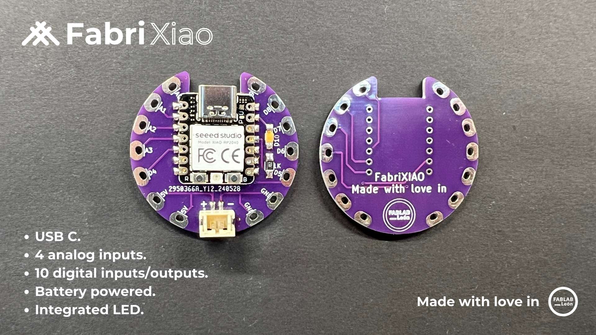
📚 Overview
FabriXiao is a small microcontroller board designed for wearable electronics and soft circuits, developed by Adrián Torres as part of Fabricademy. It is based on the Seeed Studio XIAO form factor, often using RP2040 or ESP32-C3, making it compact, programmable, and suitable for textile integration.
FabriXiao aims to provide an accessible platform for creating interactive textile projects, integrating sensors, actuators, and haptic feedback.
- 🧩 Hardware licensed under CC BY-SA
- 💻 Software compatible with Arduino IDE, CircuitPython, or MicroPython
🛠 Hardware
FabriXiao includes digital and analog I/O pins designed for wearables and textiles:
- Digital I/O Pins: Up to 11
- Analog Input Pins: 3–5 (depending on board version)
- Power: 3.3V logic, USB-C for power and programming
- Size: Ultra-compact, compatible with small textile projects
- Microcontroller: RP2040 or ESP32-C3 (depends on version)
⚙️ Key Features
- Tiny form factor for soft circuits and wearables
- Supports I2C, SPI, UART communication
- Compatible with NeoPixels, servos, and haptic actuators
- Works with pressure sensors, capacitive touch, and resistive inputs
🎛 Inputs & Outputs
FabriXiao can interface with multiple sensors and actuators:
- Inputs:
- Pressure sensors (like the ones shown in the Fabricademy tutorial)
- Capacitive touch sensors
- Force-sensitive resistors (FSR)
- Outputs:
- LEDs / NeoPixels
- Vibrating motors / haptic actuators
- Relays and small actuators
It is designed to be sewn or integrated into fabrics, connecting sensors and outputs with conductive thread or flexible wires.
💻 Software
- Programming languages: Arduino C/C++, MicroPython, CircuitPython
- IDEs: Arduino IDE, Thonny, or VS Code with PlatformIO
- Supports libraries for sensors, NeoPixels, and haptic feedback
- Easy integration with serial communication for debugging or PC control
📚 References
References & Inspiration
 Skin Electronics inspiration moodboard by Carlotta Premazzi
Process and workflow
Pressure / Sensor Matrix 5x1 → ESP32-S3 → OSC → Processing → TouchDesigner

 Sensitive Matrix 5x1 by Carlotta Premazzi
 Schematics Sensitive Matrix 5x1 by Carlotta Premazzi
📁 Files
- Matrix_1x5_ESP_OSC_5-dic-2025.ino — ESP32-S3 code (OSC sender)
- PRO_pressure_1x6_matrix_vis_grey.pde — Processing visualization
- NewProject.1.toe — TouchDesigner OSC receiver & mapping
🧩 Overview
This project enables the creation of a touch-sensitive or pressure-responsive matrix using 5 analog sensors, processed by an ESP32-S3, visualized in Processing, and mapped in TouchDesigner.
Workflow
The sensors are read through analog inputs, processed by the ESP32-S3, and transmitted wirelessly using OSC:
TOUCH / PRESSURE
↓
COPPER TAPE SENSOR
↓
Xiao ESP32-S3 Reads Analog Signal
↓
OSC Message via WiFi AP
↓
Processing (real-time visualization and debug)
↓
TouchDesigner (creative mapping and interaction)
⚙️ Hardware, Components
- Seeed Studio Xiao ESP32-S3
- 5 analog sensors (copper tape, force-sensitive, capacitive, etc.)
- Insulating tape
- USB cable, wires, solder
- Soft material (foam, neoprene, felt) for pressure layers
- Computer with Wi-Fi(Windows/Mac/Linux)
Why Only 5 Sensors? — Important Technical Note
The ESP32-S3 (especially the Xiao variant):
- does not support analog input on all pins
- has pins tied internally to USB, flash memory, PSRAM, or boot mode
- becomes unstable with high-impedance sensors
- may crash or reboot when using incompatible pins
✔️ Stable ADC Pins Used
| Sensor | Physical Pin | GPIO | ADC Channel |
|---|---|---|---|
| S1 | 1 | GPIO1 | ADC1_CH0 |
| S2 | 2 | GPIO2 | ADC1_CH1 |
| S3 | 3 | GPIO3 | ADC1_CH2 |
| S4 | 4 | GPIO4 | ADC1_CH3 |
| S5 | 5 | GPIO5 | ADC1_CH4 |
Pins 6–10, 33–35 are avoided due to noise or internal conflicts.
🟠 4. Sensor Wiring
Each copper sensor wiring:
COPPER PAD → ANALOG PIN (S1–S5)
OTHER SIDE → GND
Tips for stability":
- Isolate copper from the surface using tape
- Add a 1 MΩ resistor to GND if using capacitive materials
- Keep wires short to reduce noise
💻 Software Architecture
The project consists of three software layers:
| Layer | Description |
|---|---|
| ESP32 Arduino code | Reads analog sensors and sends OSC messages |
| Processing sketch | Real-time visualization of sensor activity |
| TouchDesigner | Maps sensor data into audiovisual or interactive content |
ESP32-S3 / Arduino IDE to OSC Transmission
File: Matrix_1x5_ESP_OSC_5-dic-2025.ino
ESP32 OSC Sensor – Arduino Example
/* ESP32 OSC Sensor – Arduino Example
Read 5 analog sensors on A0–A4, scale their values, and send them via OSC (Open Sound Control) over WiFi UDP to a PC (e.g., TouchDesigner). The ESP32 acts as a WiFi Access Point.
5-12-2025 by Carlotta Premazzi, Gulhelme Martins, Fabricademy
This example code is for educational purposes. */
include // ESP32 WiFi library
include // UDP communication library
include // Open Sound Control library
// ==================== // Global Variables // ==================== int sensorval1; int sensorval2; int sensorval3; int sensorval4; int sensorval5;
// ==================== // WiFi / UDP / OSC Configuration // ==================== const char SSID_AP = "espap"; // ESP32 AP name const char PASS_AP = "123456789"; // ESP32 AP password
// IP configuration for ESP32 Access Point IPAddress apIP(192, 168, 10, 1); // ESP32 IP IPAddress apGW(192, 168, 10, 1); // Gateway IP IPAddress apMASK(255, 255, 255, 0); // Subnet mask
// Destination IP and port for OSC messages IPAddress destIP(192, 168, 10, 255); // Broadcast IP (all devices) const uint16_t destPort = 8000; // Destination port (TouchDesigner)
WiFiUDP Udp; // UDP object
// ==================== // Setup // ==================== void setup() { Serial.begin(115200); delay(200);
// Configure ESP32 as Access Point with fixed IP
WiFi.mode(WIFI_AP);
WiFi.softAPConfig(apIP, apGW, apMASK);
WiFi.softAP(SSID_AP, PASS_AP);
delay(200);

// Debug output
Serial.println("AP active");
Serial.print("SSID: "); Serial.println(SSID_AP);
Serial.print("PASS: "); Serial.println(PASS_AP);
Serial.print("AP IP: "); Serial.println(WiFi.softAPIP());

// Start UDP on local port 9000
Udp.begin(9000);
}
// ==================== // Function to send OSC messages // ==================== void sendOSC() { OSCMessage msg("/touch"); // OSC address
// Add sensor values
msg.add(sensorval1);
msg.add(sensorval2);
msg.add(sensorval3);
msg.add(sensorval4);
msg.add(sensorval5);

// Send OSC message over UDP
Udp.beginPacket(destIP, destPort);
msg.send(Udp);
Udp.endPacket();
msg.empty(); // Clear message
}
// ==================== // Main loop // ==================== void loop() { // Read analog sensors A0–A4 and scale 0–1023 to 0–255 sensorval1 = analogRead(A0) / 4; sensorval2 = analogRead(A1) / 4; sensorval3 = analogRead(A2) / 4; sensorval4 = analogRead(A3) / 4; sensorval5 = analogRead(A4) / 4;
// Print sensor values for debugging
Serial.print(sensorval1); Serial.print("\t");
Serial.print(sensorval2); Serial.print("\t");
Serial.print(sensorval3); Serial.print("\t");
Serial.print(sensorval4); Serial.print("\t");
Serial.println(sensorval5);

// Send OSC message
sendOSC();

// Small delay (~20 messages per second)
delay(50);
}
- Configure ESP32-S3 as WiFi Access Point (SSID:
espap) - Read 5 analog values (A0–A4)
- Divide values by 4 → 0–255
- Send OSC messages on port 8000 via broadcast
Broadcast mode allows any computer in the network to receive OSC without setting an IP.
🔌 ESP32-S3 Setup — Step-by-Step
Arduino IDE Settings
- Board: your ESP32-S3 module
- Port: correct USB/COM
- Upload speed: 115200 (stable)
- USB CDC on Boot: disable if Serial fails
- Install drivers → CP2102 or CH340
- Wi-Fi must stay ON for stable boot
Serial Workflow
- Upload code
- Open Serial Monitor → Clear Output
- Close Serial Monitor
- Press RST
- Wait 1s before opening Processing
Processing → Real-Time Visualization
File:
PRO_pressure_1x5_matrix_vis_grey.pde
Processing Visualization – 5 Analog Sensors A0–A4
/ Visualization of 5 sensors (A0–A4) Format: 1 row x 5 columns Each rectangle represents a sensor value. /
import processing.serial.*;
Serial myPort; int rows = 1; // 1 row int cols = 5; // 5 columns int totalSensors = 5;
float[] sensorValue = new float[totalSensors];
int rectW, rectH;
void setup() { size(600, 400);
// Rectangle dimensions
rectW = width / cols;
rectH = 100;

println(Serial.list()); // list available serial ports

// >>> CHANGE THIS INDEX TO MATCH YOUR SERIAL PORT <<<
myPort = new Serial(this, Serial.list()[9], 9600);

myPort.clear();
myPort.bufferUntil('\n');

background(255);
rectMode(CORNER);
}
void draw() { background(255);
int index = 0;

for (int x = 0; x < cols; x++) {
    fill(sensorValue[index]);
    rect(x * rectW, 0 * rectH, rectW, rectH);

    index++;
    if (index >= totalSensors) return;
}
}
void serialEvent(Serial myPort) { String inString = myPort.readStringUntil('\n');
if (inString != null) {
    inString = trim(inString);
    String[] values = split(inString, "\t");

    if (values.length == totalSensors) {
        for (int i = 0; i < totalSensors; i++) {
            int raw = int(values[i]);
            float mapped = map(raw, 0, 1023, 255, 0);
            sensorValue[i] = constrain(mapped, 0, 255);
        }
    }
}
}
- Read sensor values via Serial (for calibration/debugging)
- Display 5 rectangles (1×5)
- Color intensity = pressure level
Useful for:
- Hardware setup
- Workshop demos
- Sensor calibration
🎨 8. Processing Setup
- Use Java mode
- Find serial port with:
java println(Serial.list()); myPort = new Serial(this, Serial.list()[2], 9600); Add a 1-second delay before opening port
Visualization: 5 rectangle, Darker = more pressure
TouchDesigner → Creative Mapping
File: NewProject.1.toe
- Receive OSC on port 8000
- Parse address
/touch - Output CHOP channels: touch0–touch4
- Drive visuals, audio, geometry, shaders, or interactions
🎚️ 9. TouchDesigner Setup Guide
- OSC In CHOP
- Port: 8000
- Broadcast: enabled
- Address: /touch
- Channels:touch0, touch1, touch2, touch3, touch4
Connect to:
- Math CHOP (scale, smooth)
- TOPs (visuals)
- SOPs (geometry)
- DATs
- Audio CHOPs
- GLSL shaders
Tools
Results
Sensor Test at Biolab Lisbon. Arduino IDE code, Processing visulization, OSC signal visulization in Touchdesigner.
Reference
📚 Research Groups & Industrial Technologies
Rogers Research Group
- Rogers Research Group (2015). Epidermal electronics research. University of Illinois at Urbana–Champaign.
Stretchable Electronic Skin
- Someya, T., & Sekitani, T. (2015). Stretchable electronic skin systems. The University of Tokyo.
Wearable Skin Sensors
-
L’Oréal (2015). My UV Patch [Wearable skin sensor].
-
MC10 (2015). BioStamp Research Connect™ [Biometric skin-mounted sensor].
🖐 On-Body Interface Research
iSkin
- Weigel, M., Lu, T., Bailly, G., Oulasvirta, A., Majidi, C., & Steimle, J. (2015). iSkin: Flexible, Stretchable and Visually Customizable On-Body Touch Sensors for Mobile Computing. Proceedings of CHI 2015.
NailO
- Kao, H.-L. C., Dementyev, A., Paradiso, J. A., & Schmandt, C. (2015). NailO: Fingernails as an Input Surface. Proceedings of CHI 2015.
🩸 Skin as Display / Biosensing Tattoos
- Vega, K., Jiang, N., Liu, X., Kan, V., Barry, N., Yetisen, A., Maes, P., & Paradiso, J. (2017). Dermal Abyss: Interfacing with the body by tattooing biosensors. Proceedings of ISWC ’17.
✨ DuoSkin – Temporary Metallic Tattoos as Interfaces
- Kao, H.-L. C., Holz, C., Yang, J., & Schmandt, C. (2016). DuoSkin: Rapidly Prototyping On-Skin User Interfaces Using Skin-Friendly Materials. Proceedings of ISWC 2016.
💄 Beauty Technology Projects (Katia Vega)
-
Hairware (2014) – Conductive hair extensions as capacitive sensors.
-
Blinklifier (2014) – Conductive makeup for eye-based interaction.
-
Winkymote (2014) – Infrared remote controlled by blinking.
-
Kinisi (2015) – Facial expression wearable interface. MIT Media Lab.
-
TechNails (2015) – Interactive nails for ambient interaction.
-
Gimmickiano (2015) – Body-based musical interface.
-
AquaDJing (2015) – Water-reactive DJ interface.
-
Interactive Carnival Masks (2016) – MIT Media Lab.
👩💻 Additional Profiles
- Katia Vega – Personal Websites and Profiles
🛠 Online Tools & Libraries
-
Adafruit Industries (2016) – LED Masquerade Mask tutorial.
-
Adafruit Industries (2016) – PN532 NFC/RFID Arduino library.
-
BeautyTech NFC Twinkle Nails (2015) – GitHub repository by Vega.
-
Hairware code repository (2015) – GitHub repository by Vega.
- Crafting On-Skin Interfaces: An Embodied Prototyping Journey
- SkinKit: Construction Kit for On-Skin Interface Prototyping
- HYBRID BODY LAB
- Song, Manlin, and Katia Vega. "HeartMe: Thermochromic Display as An Expression of Heart Health." In Proceedings of the 2018 ACM Conference Companion Publication on Designing Interactive Systems, pp. 311-314. 2018.
- Song, Manlin, Chenyu Jia, and Katia Vega. "Eunoia: Dynamically Control Thermochromic Displays for Animating Patterns on Fabrics." In Proceedings of the 2018 ACM International Joint Conference and 2018 International Symposium on Pervasive and Ubiquitous Computing and Wearable Computers, pp. 255-258. 2018.
- Kao, H.-L. C., Bedri, A., Lyons, K., “SkinWire: Fabricating a Self-Contained On-Skin PCB for the Hand”, ACM IMWUT 2018 DOI
Lecture on December 2th, 2025, Global Instructors: Katia Vega * Global Tutorial: Emma Pareschi * Local Instructors: Guilherme Martins
Student checklist
- [ ] Document the concept, sketches, references also to artistic and scientific publications
- [ ] Design a “skin-circuit”, exploring the replication of the examples bewlow or: -- [ ] the Skin masquerade party project -- [ ] the Twinkle Nails project -- [ ] interactive tattoo -- [ ] explore how to create a new skin electronics accessory.
- [ ] Document the project and included all source files and all materials used
- [ ] Upload your design files and source code
- [ ] Make a video with your skin electronic working
- [ ] Make a short performance/concept of your project functioning (extra credit)