12_SKIN ELECTRONICS
Overview + lecture
Skin electronics is a subfield of wearable electronics designed to be worn directly on the skin. In that sense, skin becomes an interface, a display through which different technology can perform. This week, we got an insight into the possibilities and applications of this scientific and artistic field of electronics, learning to use the body's physical features and combining them with an electronic system.
Starting with Katia Vega presentation and the term beauty technology, a new subfield of wearable computing that embeds electronics into cosmetics. A conductive makeup, nails embedded with RFIDs, electroplated hair extensions as sensors and FX e-makeup that detects facial movements, are a few of her research projects.
Fields of application and important to consider:
Diving into the research, other fields of applications of skin electronics technologies are also: biometric monitoring, health monitoring, medical diagnostics, wellbeing, human-machine interactions, human-computer interactions, rehabilitation and prosthetics, emergency and surveillance, military and defence, sports, fitness, wellbeing, fashion and decoration purposes, tattoos.. Transforming the future of electronic devices and human interactions, as a human-device symbiosis concept, an important thing to consider is the collection of the information data these devices can track and store. What are the implications of the technology, who designs it and for what reason? Are they designed to control, harm or help us? To whom these information are valuable?
General References
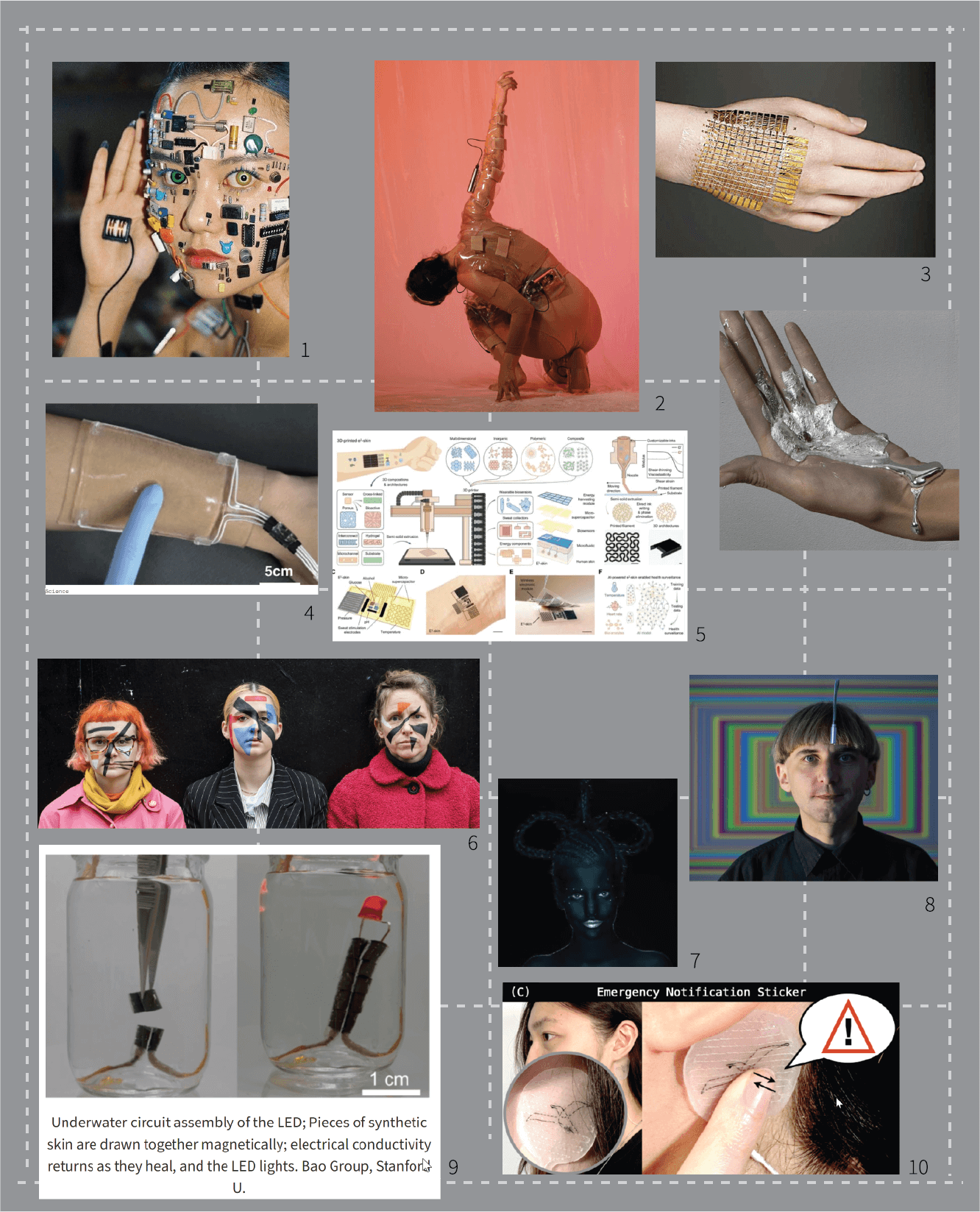
1 - John Yuyi, Sin título, 2019
2 - Transceptor project by Citali Hernandez
3 - Electronic skin, Ulsan National Institute of Science and Technology
4 - Stretchable transparent wearable touchpad made of hydrogel, Seoul National University
6 - Reverse contouring, anti-facial recognition make-up by Emily Roderick
8 - Neil Harbisson, the first person in the world with an antenna implanted in his skull
9 - Self-healing electronic skin, Stanford University
10 - Skinergy on-skin sensors, emergency notification sticker
Materials
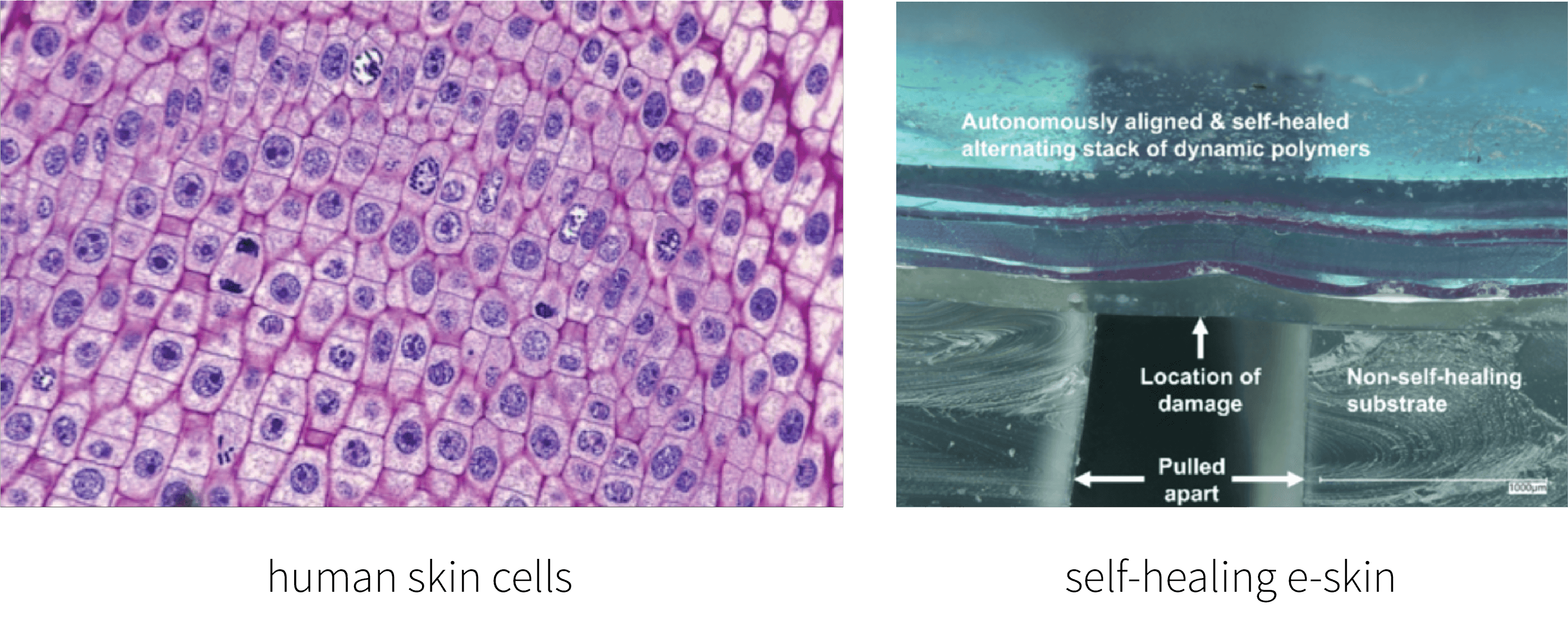
As presented, the main ''material'' or component this week is the human body – body parts, skin, hair, nails and all of its features. While doing the research, I came across a project led by Professor Zhenan Bao at Stanford University, where the team engineered a self-healing electronic skin. It can sense temperature, pressure and texture, it's able to stretch and spring back and provides a barrier between the body and different bacteria, viruses, toxins and even UV light. The multi-layer, thin-film sensor automatically realigns during healing. If layers are cut, sliced or punctured, they will selectively heal with themselves to restore the overall function of the e-skin. I found the smart material aspect of the topic really interesting, and would love to explore its possibilities and applications further, perhaps in combination with gel-like, soft biomaterials and biopolymers.
-
Human body
-
Body features: sweat, temperature, hormone levels, sugar levels, touch...
-
Conductive materials
-
Conductive inks
-
Conductive paint
-
Wires, tapes
-
Metals
-
Magnetic materials
-
Silicones
-
Hydrogels
-
Polymers
-
Biopolymers
-
Biomaterials
-
Biosilicones
-
Electronic components...
Class with Citali
This week we started prototyping with Citali and made a skin pressure sensor and a skin matrix sensor, a 3x3 pressure grid. We also got an insight into array function.
Skin pressure sensor
Materials used:
-
Velostat
-
Conductive thread
-
5k, 3k and 1k ohm resistor test
-
Double sided tape
-
Isolating tape
-
Multimeter
-
Arduino Uno R3
Software: Arduino IDE

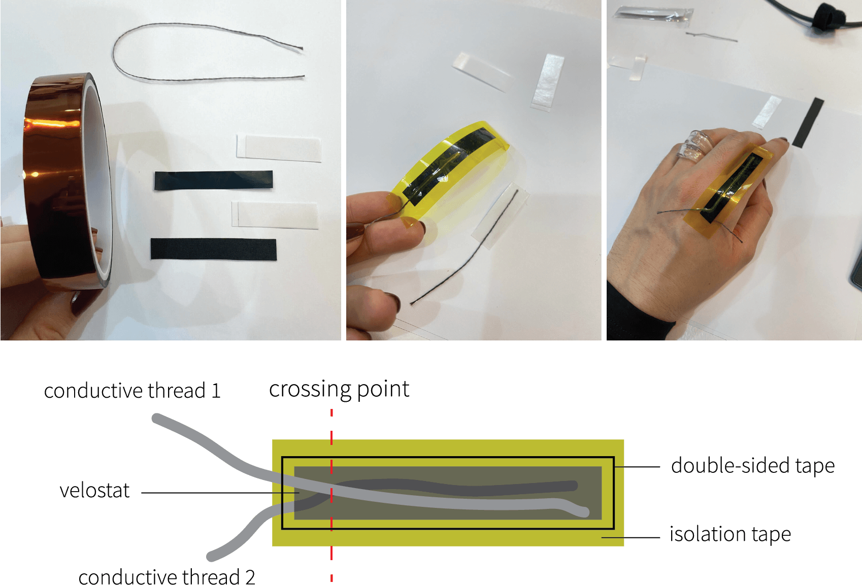
Note: The longer the design of the skin sensor, the less resistive it is. Therefore, the readings of the multimeter are lower, and the values in Arduino as well. Also, you have to make sure that the threads do meet in at least one point, but not all the way.
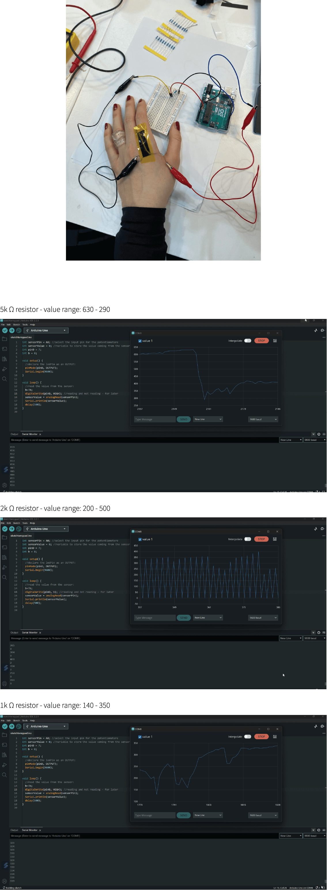
We placed the skin sensor on the knuckles of our hands, a place where there is the most tension when fingers are bent and extended, therefore creating more resistance and proper readings. The movements have to be done slowly because the sensor is quite sensible.

Connecting skin sensor with Arduino:
By reading the multimeter values, the resistance spam was between 5 K Ohm when relaxed and 1 K Ohm when I squeezed the palm. After knowing the resistance values, we were able to connect the sensor to the Arduino. I did tests with different resistors, 5 K Ohm, 3 K Ohm and 1 K Ohm, just to see which one gave me the best readings. The values are written on top of each reading. The 1 K Ohm was the most accurate in terms of properly reading the values from the sensor, so I continued with 1 K Ohm resistors.
Arduino code we used for readings:
int sensorPin = A1;
int sensorValue = 0;
int pinD = 7;

void setup() {
  pinMode(pinD, OUTPUT);
  Serial.begin(9600);
}

void loop() {
  sensorValue = analogRead(sensorPin);
  Serial.println(sensorValue);
  delay(500);
}
Skin matrix sensor
Afterwards, we continued to design a skin matrix sensor. A 3x3 point grid creates 9 sensor reading points that we would be able to incorporate into our own project.
Pressure matrix code and circuit can also be found here
Materials used:
-
Tracing paper
-
Velostat
-
3 x 1k ohm resistor: for 3 analog and 3 digital pins
-
Copper tape 0.5mm
-
Wires
-
Breadboard
-
Arduino Uno R3
Softwares: Arduino IDE, Processing
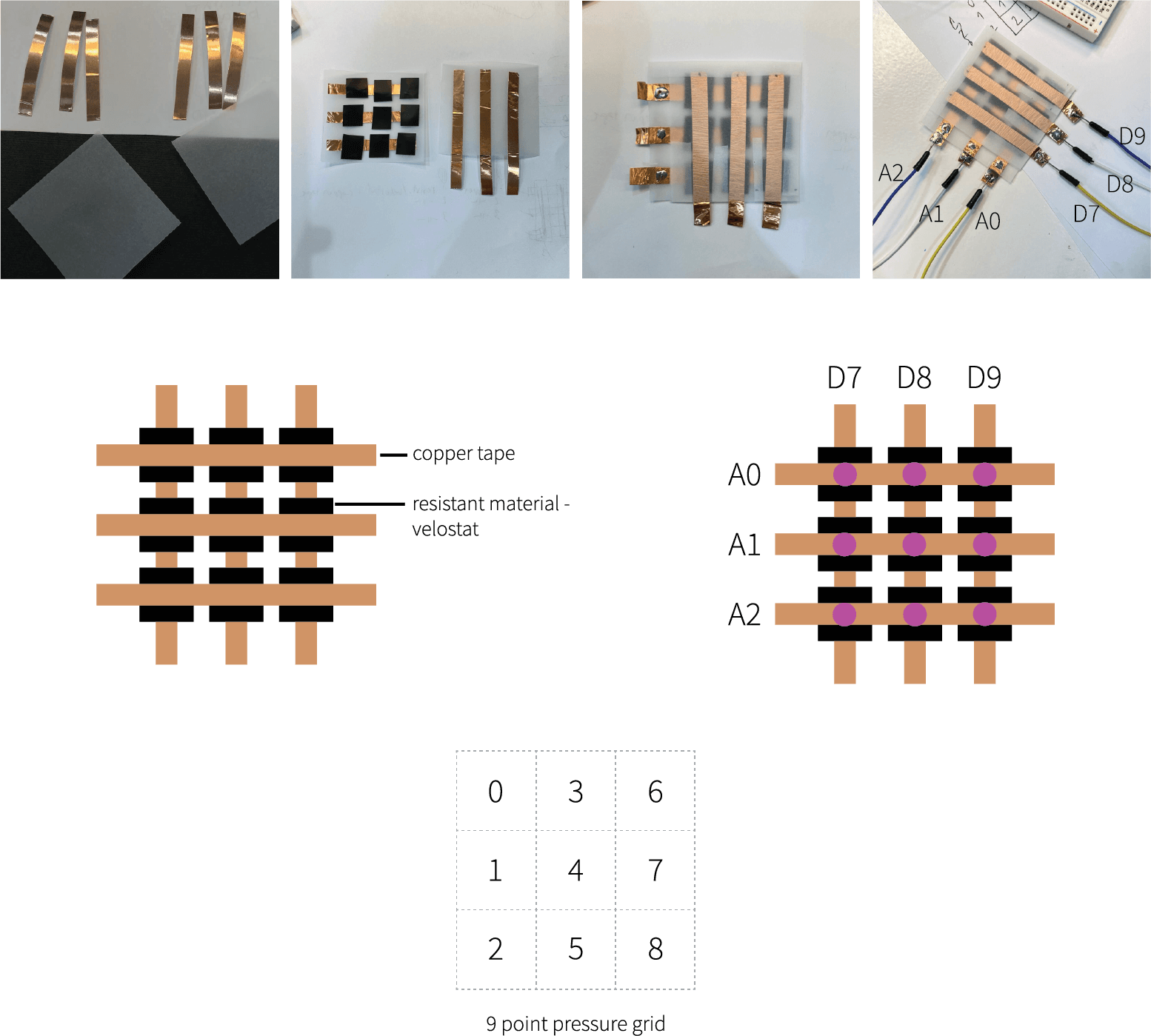
A grid is made of 3 columns and 3 rows, crossing each other at 9 different points. These points need to be separated between the copper tapes (9) with a resistive material, creating pressure sensors
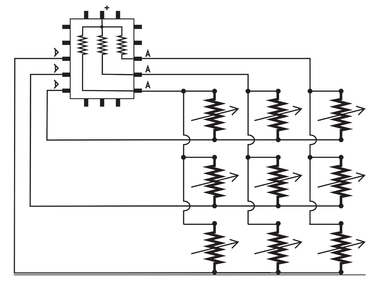
To make the design of the matrix more stable, I soldered the wires and the copper tapes. Each of the 3 rows is connected to analog pins (A0, A1, A3), and each copper tape creating columns is connected to digital pins (D7, D8, D9) on the Arduino Uno3 board.
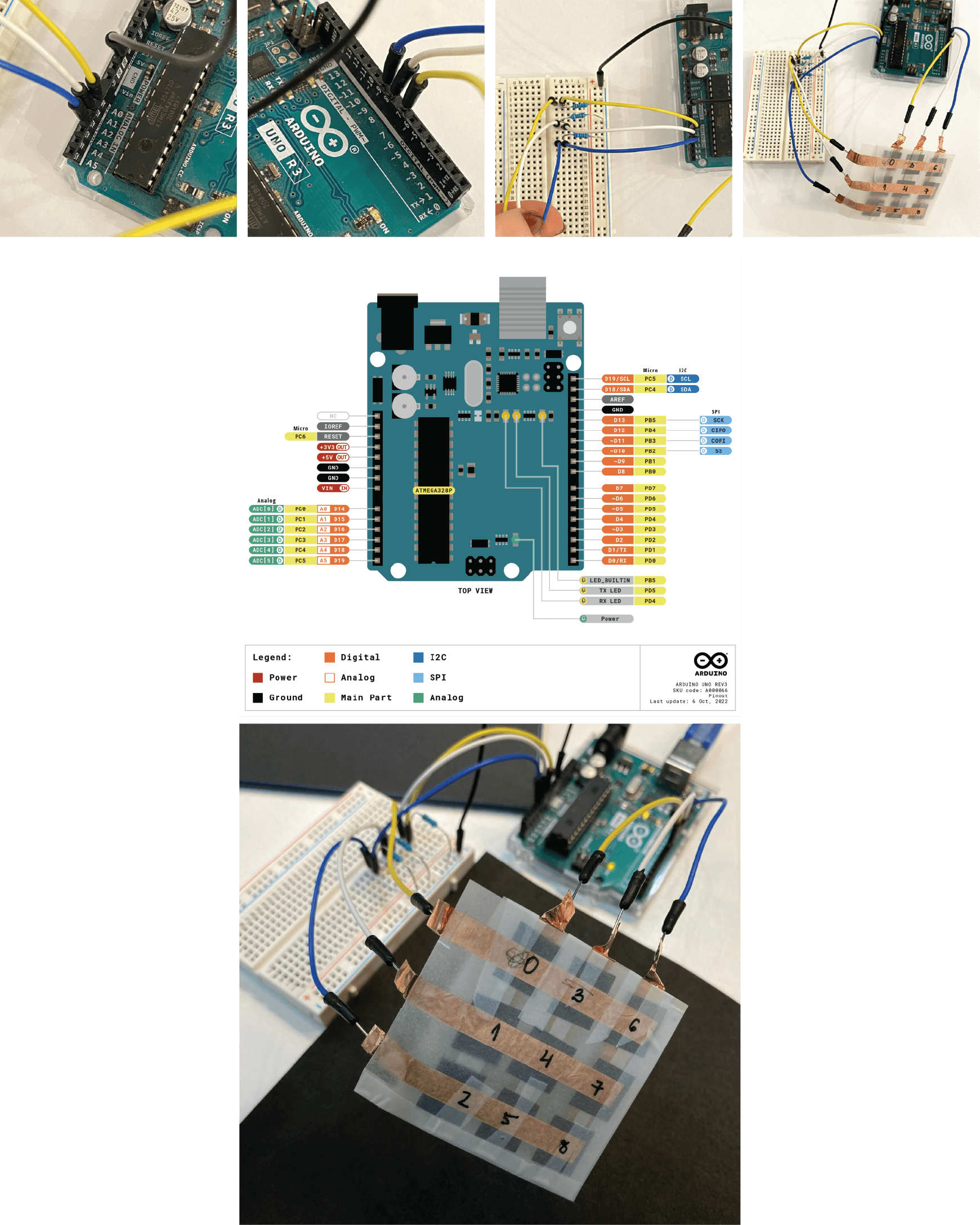
Connecting the matrix sensor with Arduino:
Note: the number, order of the pin connected to the matrix, gives away the position of the sensor, affecting the array function. It is important to connect pins properly. And, each analog pin is connected to the resistor of the same value (1 K Ohm gave my matrix the best readings).
Once designed, we used the following code to read the values of the sensors:
#define numRows 3
#define numCols 3
#define sensorPoints numRows* numCols

int rows[] = { A0, A1, A2 };
int cols[] = { 7, 8, 9 };
int incomingValues[sensorPoints] = {};

void setup() {
  for (int i = 0; i < numRows; i++) { pinMode(rows[i], INPUT); }
  for (int i = 0; i < numCols; i++) { pinMode(cols[i], OUTPUT); }
  Serial.begin(9600);
}

void loop() {
  for (int colCount = 0; colCount < numCols; colCount++) {
    digitalWrite(cols[colCount], HIGH);
    for (int rowCount = 0; rowCount < numRows; rowCount++) {
      incomingValues[colCount * numRows + rowCount] = analogRead(rows[rowCount]);
    }
    digitalWrite(cols[colCount], LOW);
  }
  for (int i = 0; i < sensorPoints; i++) {
    Serial.print(incomingValues[i]);
    if (i < sensorPoints - 1)
      Serial.print("\t");
  }
  Serial.println();
  delay(100);
}

Connecting the matrix sensor with the Processing software:
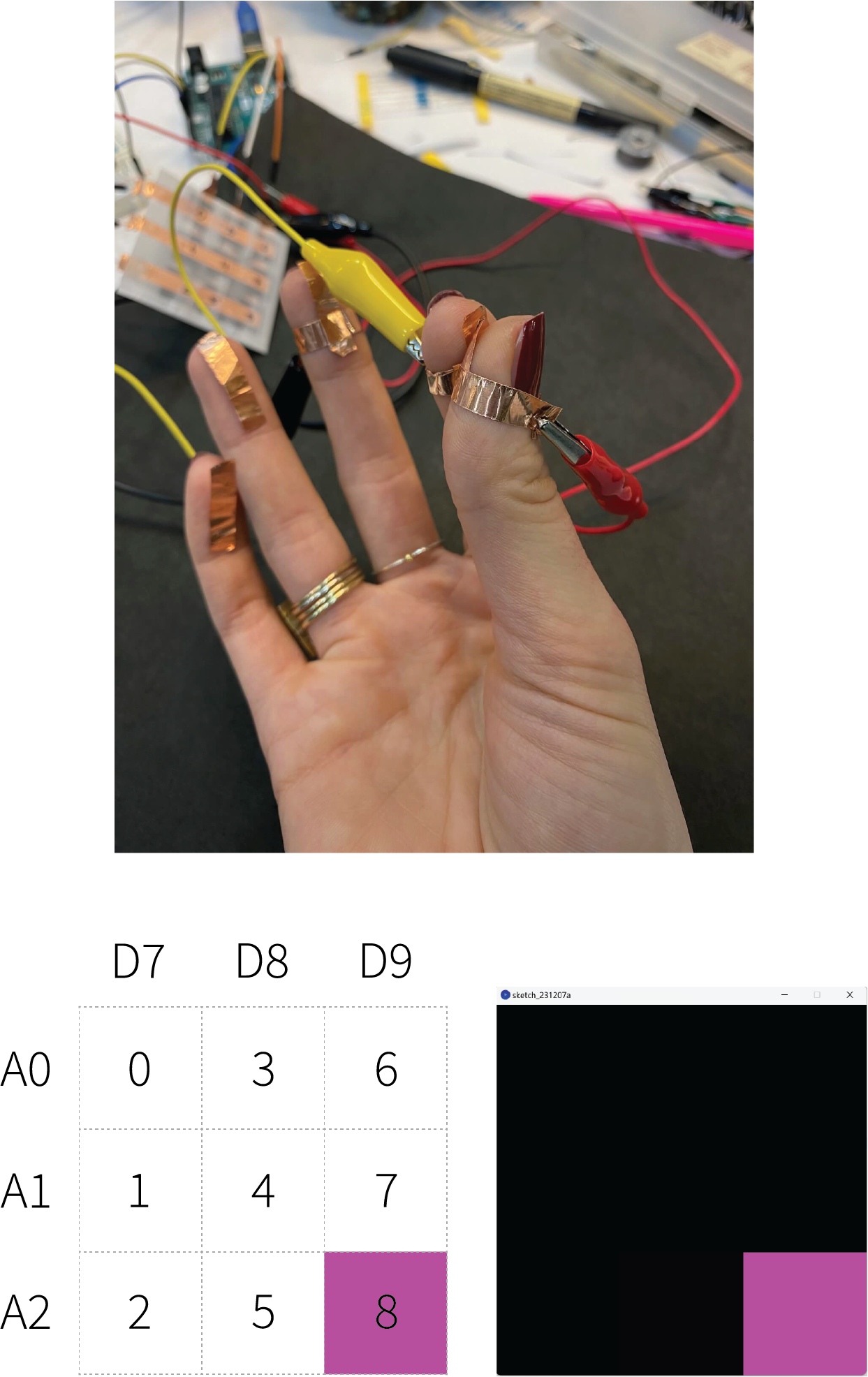
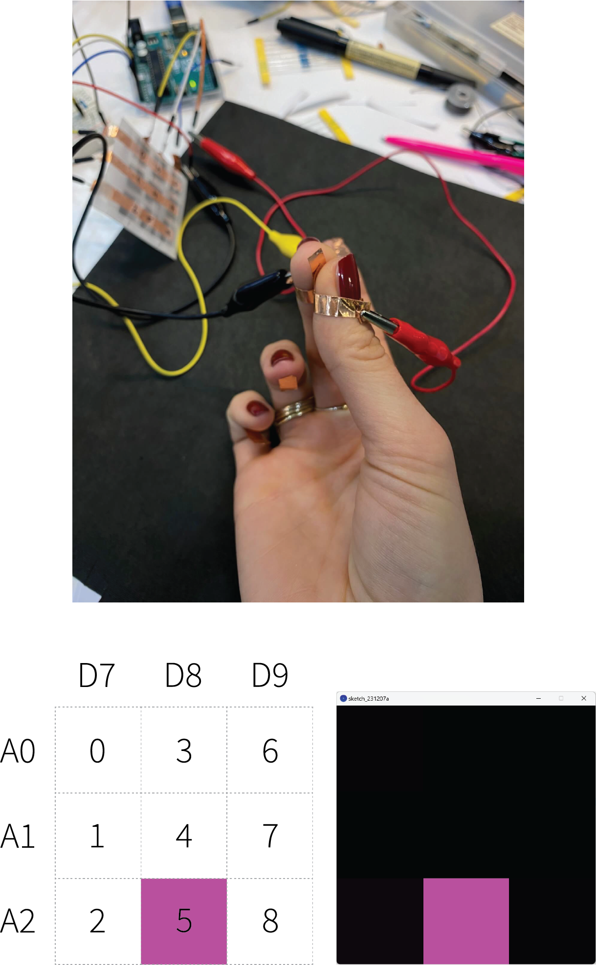
After Arduino readings, we used Processing software to visualize the data of the matrix sensor. Depending on the pressure applied and the location of it, the Processing sketch visualizes it. The number of the sensor is shown as the location and the applied pressure as the colour hue. The more you press the sensor, the colour hue intensifies. Note: Make sure Arduino IDE program is closed before using the Processing software.
The following code:
Serial myPort; // The serial port
int rows = 3;
int cols = 3;
int maxNumberOfSensors = rows*cols;
float[] sensorValue = new float[maxNumberOfSensors]; // global variable for storing mapped sensor values
float[] previousValue = new float[maxNumberOfSensors]; // array of previous values
int rectSize = 0;
int rectY;
void setup () {
  size(600, 600); // set up the window to whatever size you want
  rectSize = width/rows;

  println(Serial.list()); // List all the available serial ports
  String portName = Serial.list()[0]; // set the number of your serial port!
  myPort = new Serial(this, portName, 9600);
  myPort.clear();
  myPort.bufferUntil('\n'); // don’t generate a serialEvent() until you get a newline (\n) byte
  background(255); // set inital background
  smooth(); // turn on antialiasing
  rectMode(CORNER);
}

void draw () {
  for (int i = 0; i < maxNumberOfSensors; i++) {
    fill(sensorValue[i], 0, sensorValue[i]);
    rect(rectSize * (i%rows), rectY, rectSize, rectSize); //top left
    if ((i+1) % rows == 0) rectY += rectSize;
  }
  rectY=0;
}

void serialEvent(Serial myPort) {
  String inString = myPort.readStringUntil('\n'); // get the ASCII string
  println("test");
  if (inString != null) { // if it’s not empty
    inString = trim(inString); // trim off any whitespace
    int incomingValues[] = int(split(inString, "\t")); // convert to an array of ints

    if (incomingValues.length <= maxNumberOfSensors && incomingValues.length > 0) {
      for (int i = 0; i < incomingValues.length; i++) {
        println("Raw sensor value: " + incomingValues[i]);
        sensorValue[i] = map(incomingValues[i], 0, 1000, 0, 255);
        println("Mapped sensor value: " + sensorValue[i]);
      }
    }
  }
}

Processing visualization pressing 1, 4, 5, 7, 8 sensors of the matrix.

Visual upgrade
Coding in Processing and making different visuslizations.
- Louise Massacrier (https://class.textile-academy.org/2022/louise-massacrier/Assignments/week13/#skin-electronics-project)
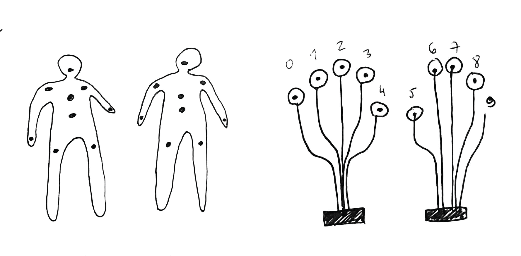
Ideation
I wanted to incorporate the designed matrix into a wearable on-skin circuit that could be used on the hand, for showing a certain gesture or as other communication tool. Fingertips as a crucial body's object for sensing, the electronic tool would act as an extension or amplifier of a certain sensation...

Process
Disconnecting the analog pins from the breadboard and connecting them to the copper tape placed on my fingertips. For that test I didin't used velostat in-between, just to play with the interaction of closing the circuit and visualizations that appeard in the Processing software.
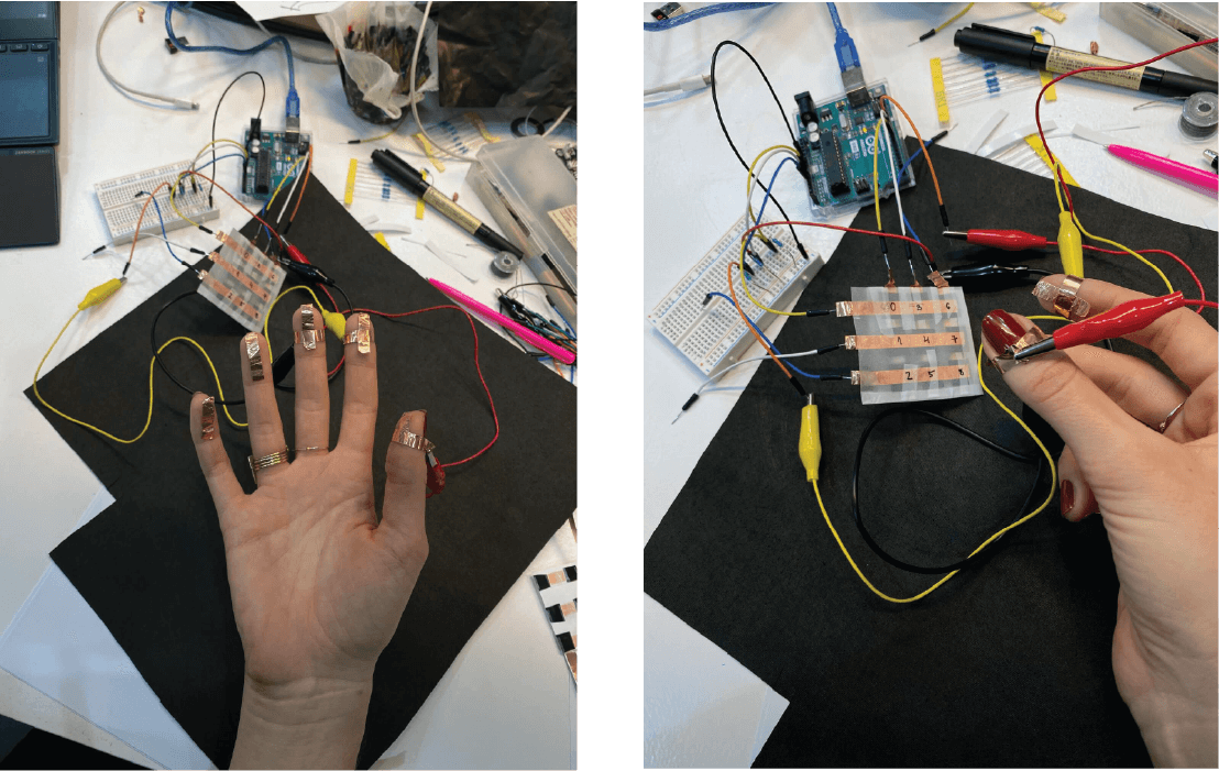
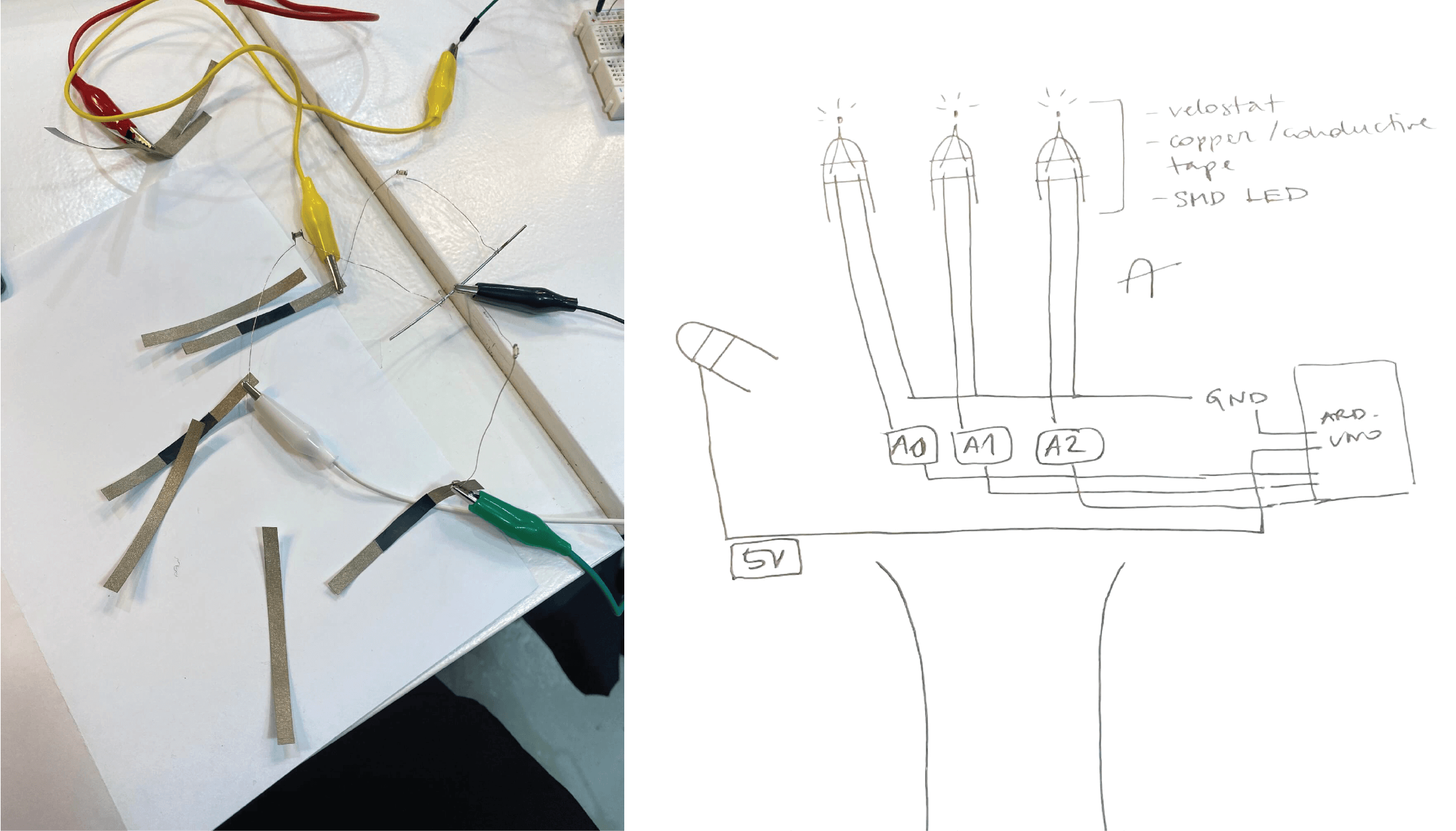
Connecting the circuit with SMD LEDs.
Next step was creating the circuit on the hand with a conductive tape and reading the values of the pressure.


Transforming the circuit sketch onto hands and fingertips and preparing the material for the on-skin wearable.
Materials used:
-
Conductive tape
-
SMD LEDs
-
Velostat
-
Arduino Uno R3
The result...

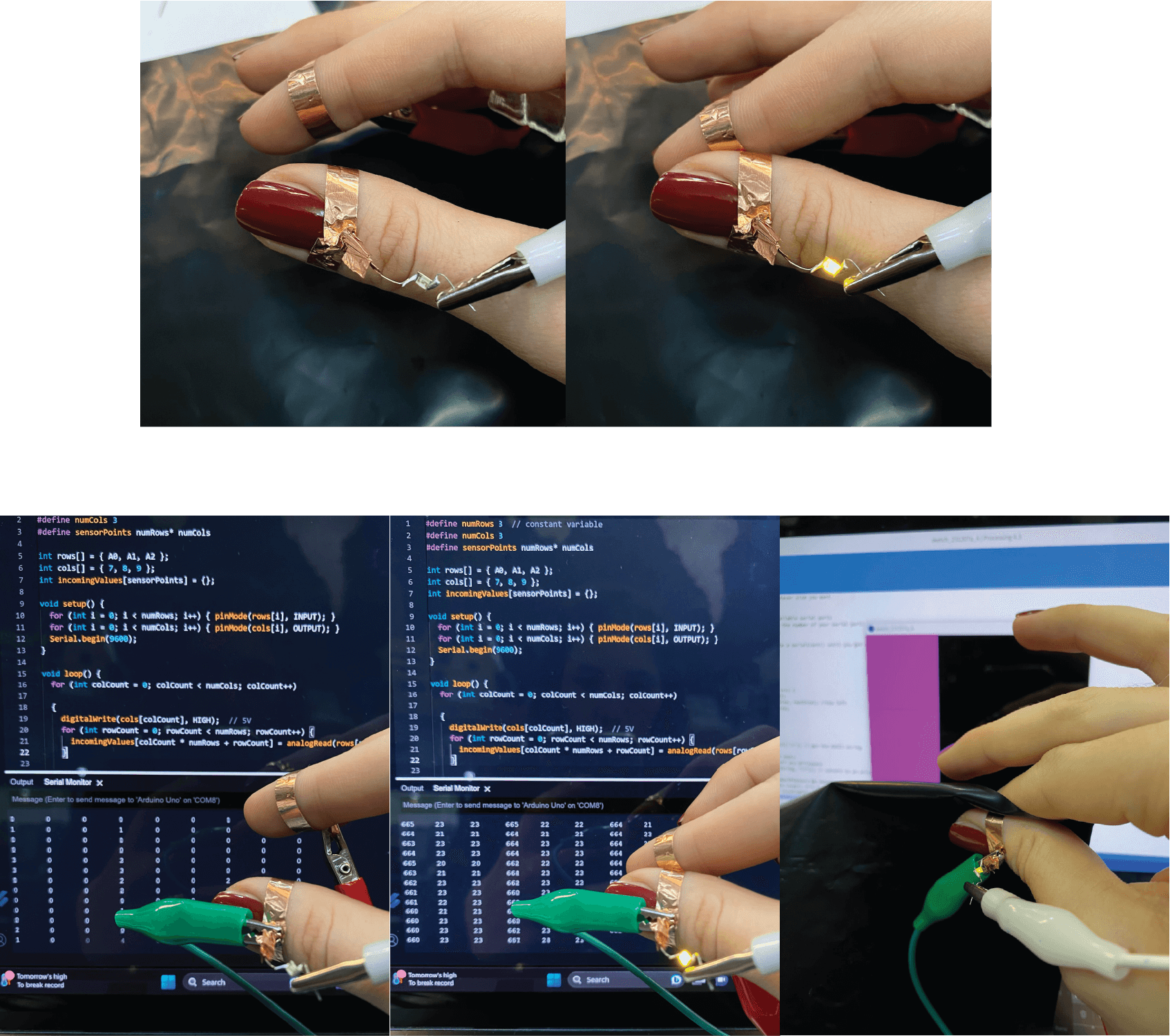
Connecting it to Arduino and Processing software, using the pressure readings from testings.
When each of the fingers closes the circuit, the LED lights up. Depending on the pressure of the touch applied, the intensivity of the light can be controlled. The Processing screen sketch visualizes the action.
Video
Note: velostat placed directly on the conductive tape on the fingertips didn't work well. For the purpose of presentation I used a bigger sheet of the velostat. Therefore, the wearble needs to be redesigned and tested again.