12. Skin Electronics
.
It's hard to imagine bridging the gap between our bodies and technology even further when we already feel so intertwined. Like many others, when I hear about electronic wearables I immediately begin to question our evolving relationship to privacy. I also struggle with the idea of reducing the complexities of having a body into a portion of a dataset.
Though I live in Amsterdam currently, my usual home base is Baltimore, Maryland in the United States. After an uprising in 2015 due to police brutality, surveillance became very prominent in the city. At one point in time there was a 24/7 live feed plane that flew over the entire city and was able to track almost anyone. During protests in 2021 I started to see people online developing makeup looks that fool facial recognition technology used by police allowing you to protest anonymously. I wanted to make a project inspired by this, using SMD LEDs that you can turn on and off giving you the power to choose when you are seen.
When do you want to be seen?
All Light Everywhere documentary
Data Feminism by Catherine D'Ignazio and Lauren Klein
"who is doing the work of data science (and who is not)? Whose goals are prioritized in data science (and whose are not)? And who benefits from data science (and who is either overlooked or actively harmed)?"
Research, References and Inspiration
 Joy Buolamwini and algorithmic bias

Hito Steyerl, How Not to be Seen: A Fucking Didactic Educational .MOV File, (2013).
Adam Harvey's "CV Dazzle" computer vision camouflage

CV Dazzle inspired makeup for protesting with anonymity. Rhinstones added for light obstruction. However many people expirmenting with the CV dazzle techniques warn that makeup can make tear gas cling to the skin for longer.
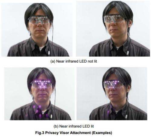
Isao Echizen and Seiichi Gohshi's light based privacy glasses
Ideation and Sketching
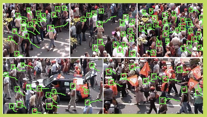
I wanted to test out this idea to see the how light interacted with facial recognition. I used Visage Technologies free demo. This demo is able to track, recognize and analyze faces in real time. It even has options to analyze age, gender and emotions.

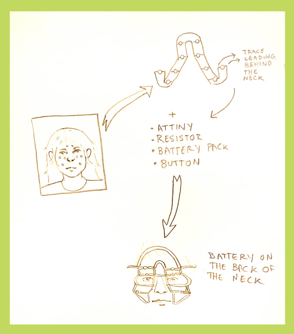
Just using my phone light was enough to confuse the system but I knew the LEDs in our lab were much dimmer. I figured a collection of smaller, lower power LEDS concentrated around key points of the face for machine recognition might also do the trick.
Tools
| Tools |
|---|
| Wire stripper |
| Soldering Iron |
| Solder |
| Coated copper wiring |
| SMD LEDs |
| Multimeter |
| 5v battery pack or coincell battery |
| Push button |
| ATtiny 25 |
| Arduino Uno |
| Breadboard |
| Jumper wires |
| Heat shrink tubes |
| Hot gluegun and glue |
| Eyelash glue |
| silicon |
Soldering SMD LEDs
I wanted to use SMD LEDS (Surface Mount Device Light Emitting Diode) because they are so small which is nice for electronics close to the skin.
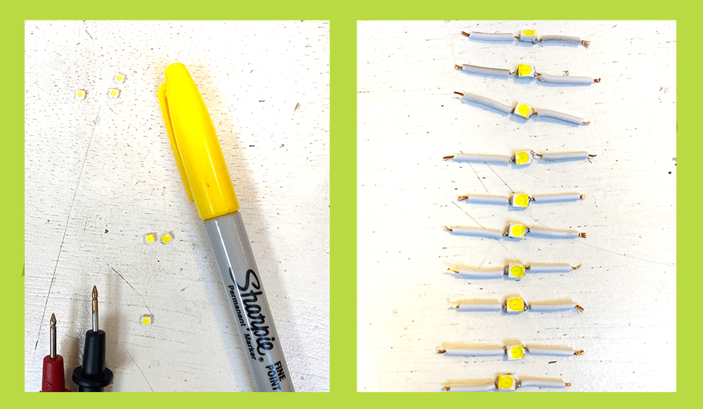
Theres no real indicator for the power and ground connections for these LEDS. I used a multimeter to test the sides and then marked them with a yellow sharpie so I didn't go crazy trying to keep track as I started building my circuit.
If you're new to soldering here is a tutorial to make nice connections
I taped my wires to hold them in place while I did my soldering
Trial 1
This is my first test I made. The power and ground are attached to a coincell battery with alligator clips that I am pressing to turn it on and off. However the I was still very visable to the computer because my nose and mouth are still very visable which are important tracking points.
I tried to screen record a video of me testing it with the visage demo but I realized it didn't save oops! but just take my word for it, it didn;t work very well.
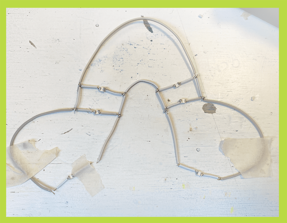
I added more LEDs around the mouth and nose to fix this problem.
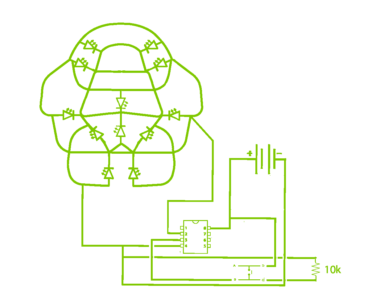
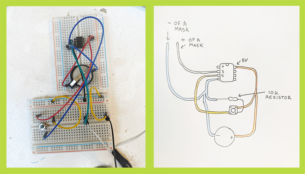
Circuit Diagram
Adding a Push button
This tutorial was really helpful in prototyping an on and off push button

One thing I learned this week is the seperation in the breadboard breaks the connection. The first time I made this circuit I didn't place the pushbutton over the break so my LED got lots of weird flickering. After way too long of not knowing this, I moved the Button and the circuit worked :-)
I first tested the circuit with one LED on a breadboard but eventually tried my whole multi LED circuit.
I ended up removing the 220 Ohm resistor attached to the LED because I was powering lots of LEDs instead of one and my lights needed to be super bright to confuse the camera
Code
#define LED_PIN 8
#define BUTTON_PIN 7
byte lastButtonState = LOW;
byte ledState = LOW;
unsigned long debounceDuration = 50; // millis
unsigned long lastTimeButtonStateChanged = 0;
void setup() {
  pinMode(LED_PIN, OUTPUT);
  pinMode(BUTTON_PIN, INPUT);
}
void loop() {
  if (millis() - lastTimeButtonStateChanged > debounceDuration) {
    byte buttonState = digitalRead(BUTTON_PIN);
    if (buttonState != lastButtonState) {
      lastTimeButtonStateChanged = millis();
      lastButtonState = buttonState;
      if (buttonState == LOW) {
        ledState = (ledState == HIGH) ? LOW: HIGH;
        digitalWrite(LED_PIN, ledState);
      }
    }
  }
}
Programming an ATtiny
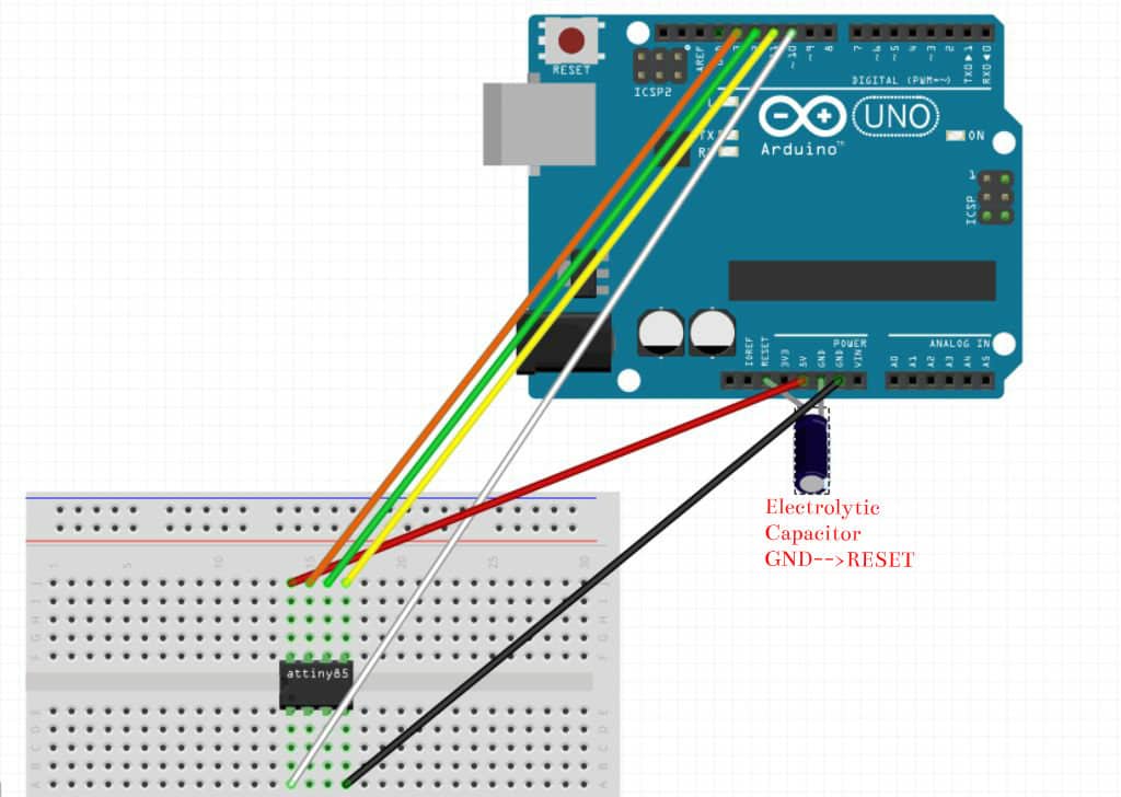
I didn't want my final circuit to use an Arduino Uno because it would be far too big for electronics close to the skin. I instead decided to program an ATtiny to minimize bulk. Since whar I was doing was fairly simple I used an Attiny 25 instead of the 85 I used in past weeks.
This tutorial was really helpful for working with the ATtiny. The image below is from this tutorial.
-
Open up preferneces in Arduino and copy this URL
https://raw.githubusercontent.com/damellis/attiny/ide-1.6.x-boards-manager/package_damellis_attiny_index.json
into additonal boards and URLS -
Install ATtiny in boards manager
-
Restart Arduino IDE
-
Select board Attiny 85
-
Open up the example sketch "Arduino ad ISP" and upload to your Uno
-
Now using the image above, use your breadboard to connect your attiny to your Arduino Uno
-
In tools select ATtiny 85 as your board, 8 MHz (internal) as your processor and Arduino as ISP as the programmer
-
Burn boatloader
** Press on your ATtiny while burning the bootloader and uploading sketches because often the connection is not good. This might cuase error messages to occur **
- Now you can upload sketches to your attiny! I started with a basic blink example sketch to make sure everything is working before attaching my push button circuit.
** Remeber to edit your sketch to reflect the pin out of the ATtiny. I changed pin 8 and 7 to 3 and 4 **
Adjustments for wearablility
To make the circuit a bit more comfortable for close to the skin wear I used heat shrink tubing on soldered connections between wires. Around the LEDs I added little drops of hot glue as well.
Make sure all connections are very secure before doing either of these steps because it becomes much harder to resolder after these are added
I used some leftover silicon to make the ATtiny, push button and battery back have something to rest on that would be comfortable against the skin. I just used a needle and thread to sew the wires into the silicon to secure them but this also could be done my glueing them with more silicon.

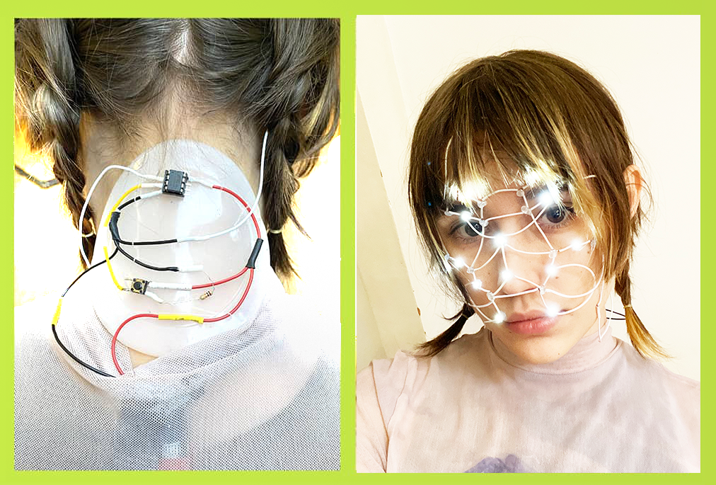
I also ended up replacing the coincell for a battery pack for the final documention/performance because the LEDs were too dim powered by just the 3v coincell.
Results and Reflections
-
I used eyelash glue to secure the mask to my face and places the button and rest of the circuit on the back of my neck.
-
The wearable works but its a bit unreliable unless in dim/dark lighting
-
Also after about 20 minutes of wear time I already broke some connections of wires. The circuit for the face is really delicate and to be functional would need to be way more secure.