12. Skin Electronics
Research
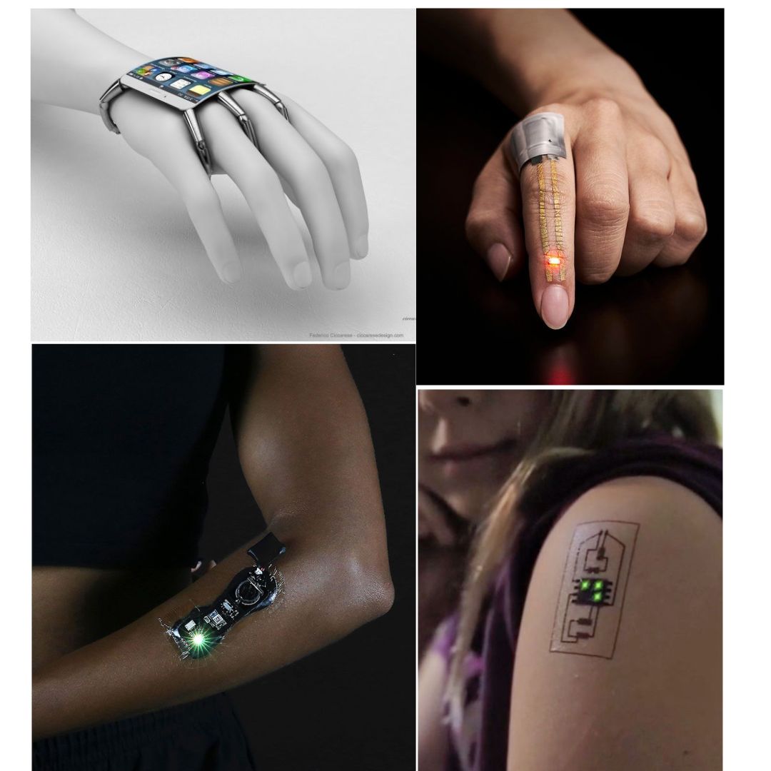
This week’s assignment began with reflecting on how it would differ from the wearable week. I looked back at my previous experience, where my focus was mainly on creating wearable pieces without fully understanding the broader possibilities within the field. At that time, I didn’t even know that skin electronics were being used, which made this new exploration feel both surprising and exciting. As I started this assignment, I became more aware of how technology can interact directly with the body, opening up new creative directions. This realization sparked my curiosity and motivated me to experiment further, pushing beyond what I had previously done and embracing the opportunity to explore unfamiliar tools, materials, and concepts.
References & Inspiration
-
koba kant KOBA Electronic Textile Tailor Shop is a shop that offers bespoke wearable technology. Everything we make is made-to-order. The shop is an artistic experiment exploring what we, as regular people wish technology to be.
-
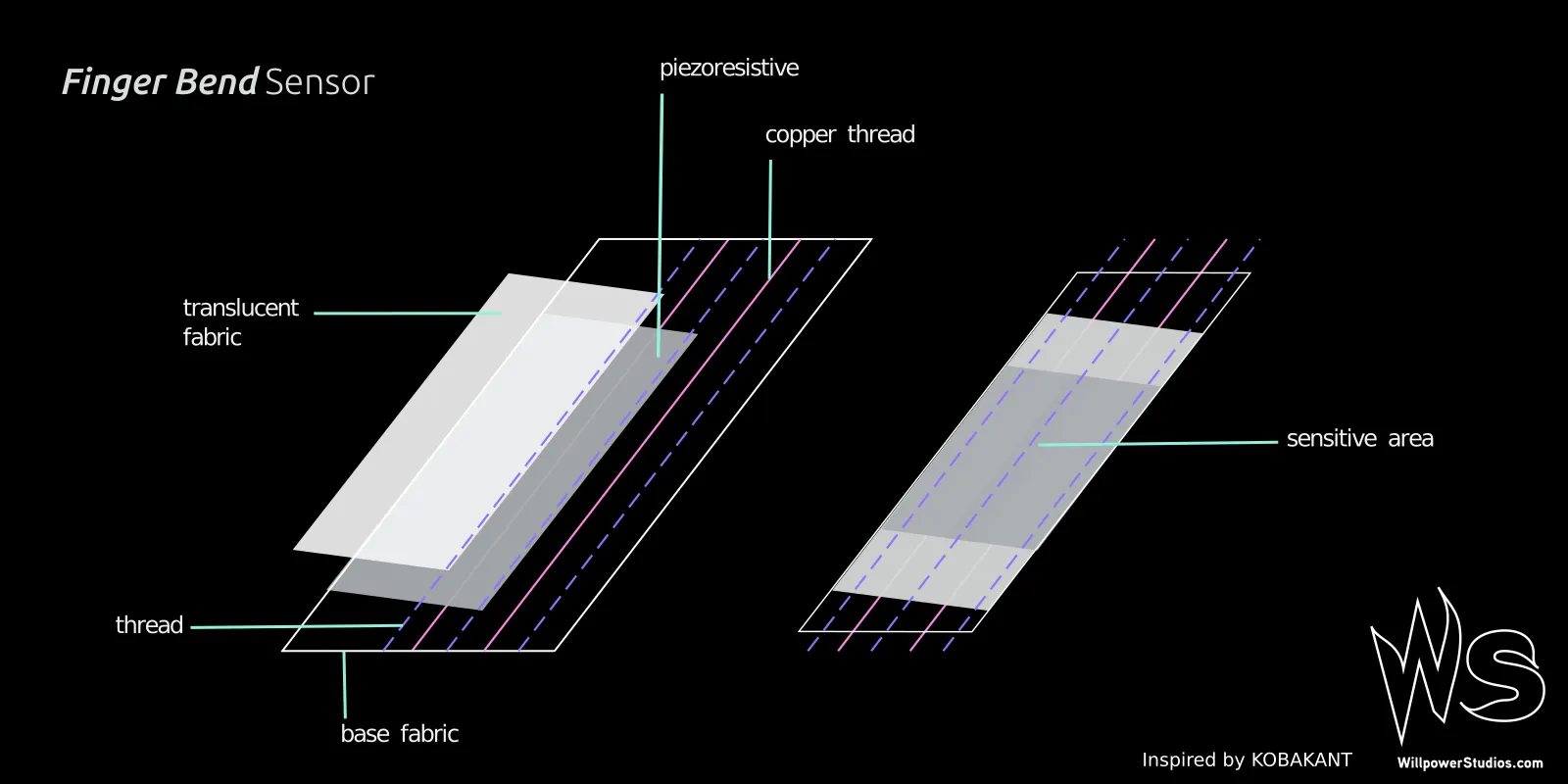
sheath bend sensor textile bend sensor constructed by sewing two parallel sheath
-
instructables Finger Bend is a sensor created to find a way of making finger bends inside of a glove, control light and sound.
Tools
× LED
× Breadboard
× Computer with arduino and the library for the microcontroller* you are using if it is not yet installed
× USB cable
× Lighter or heat gun
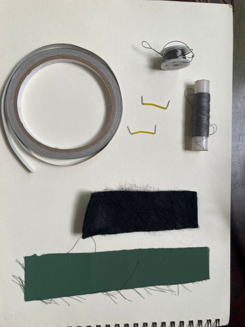
Materials
× 2nd Non-Conductive Fabric
× Copper or Other Low Resistance Conductive Thread
× non-conductive thread
× 2 Male Pins
Process and workflow
Step1
Step2: How Finger Bend is made
Step3: let's start
. Cut the stretch jersey fabric to the length of your finger from the knuckle to the beginning of your nail and width of ~ 8 cm.
. Cut a piece of stretchy piezoresistive material and top fabric, both at the same size.
. Place piezoresistive stretchy fabric in between the base and top fabrics.
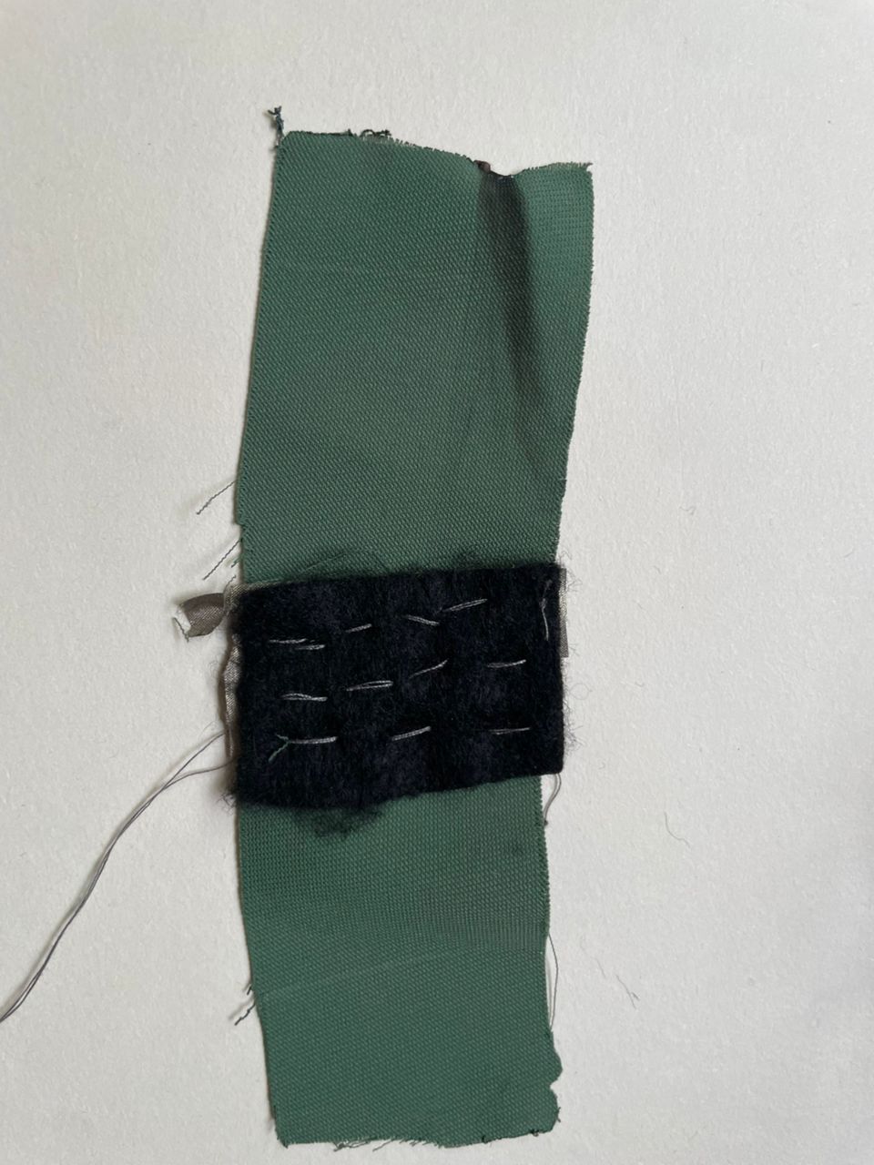
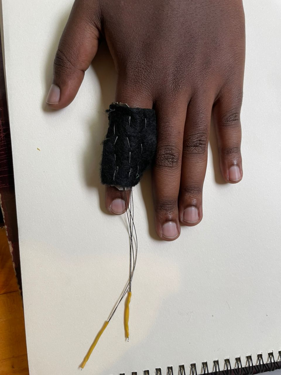
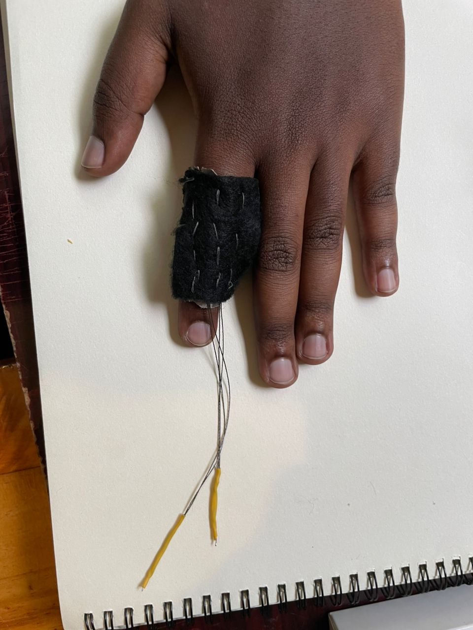
Step 4: Sew 3 lines to slide the 2 copper Threads in between them
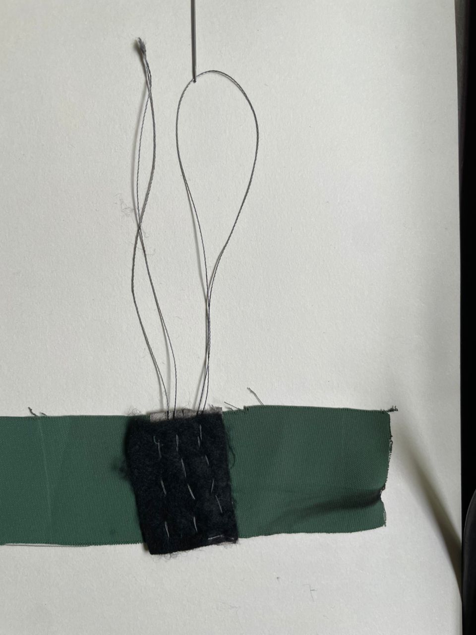
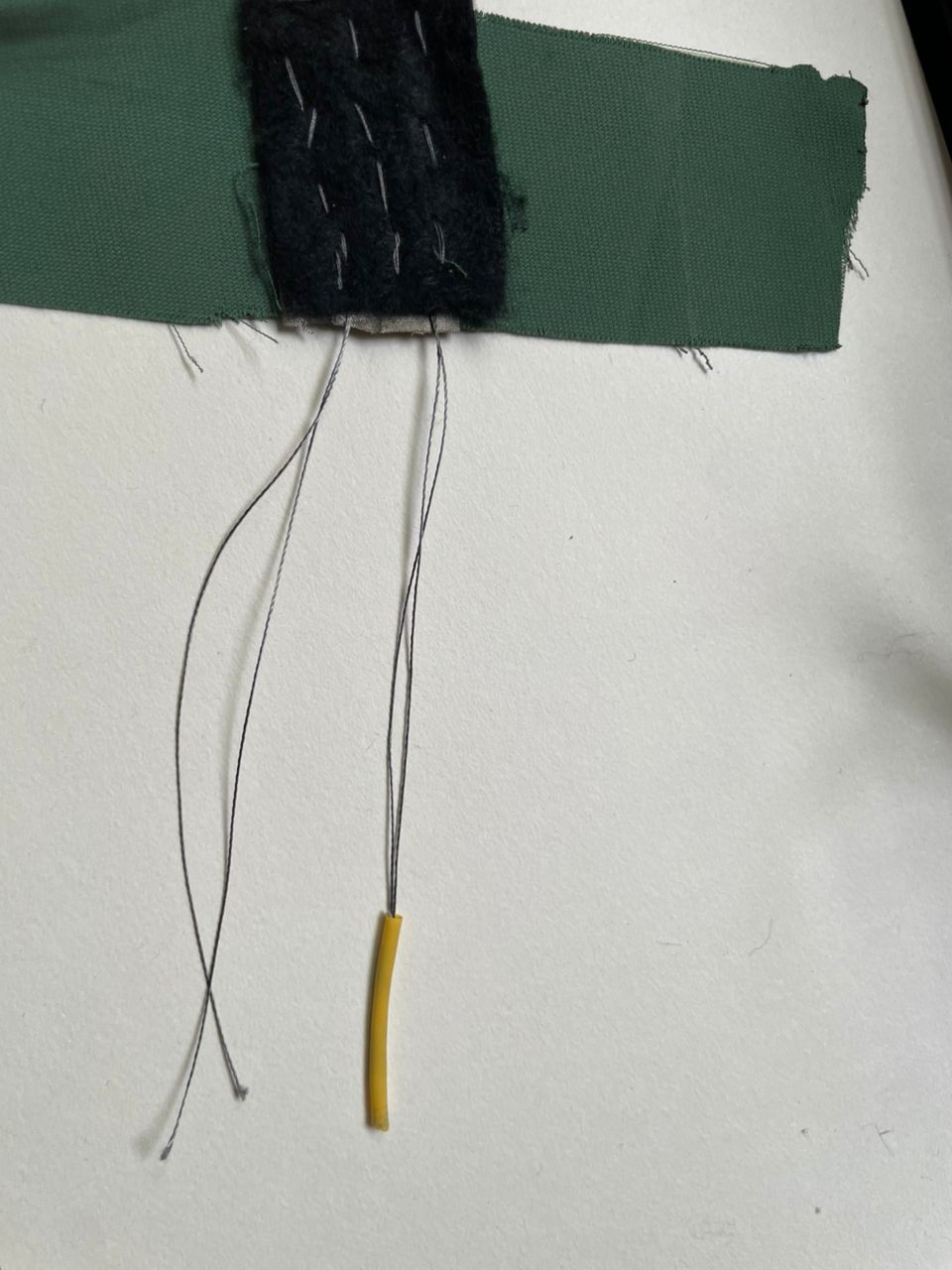
Step 5: Add a male pin both sides on the copper tread and a shrink tube
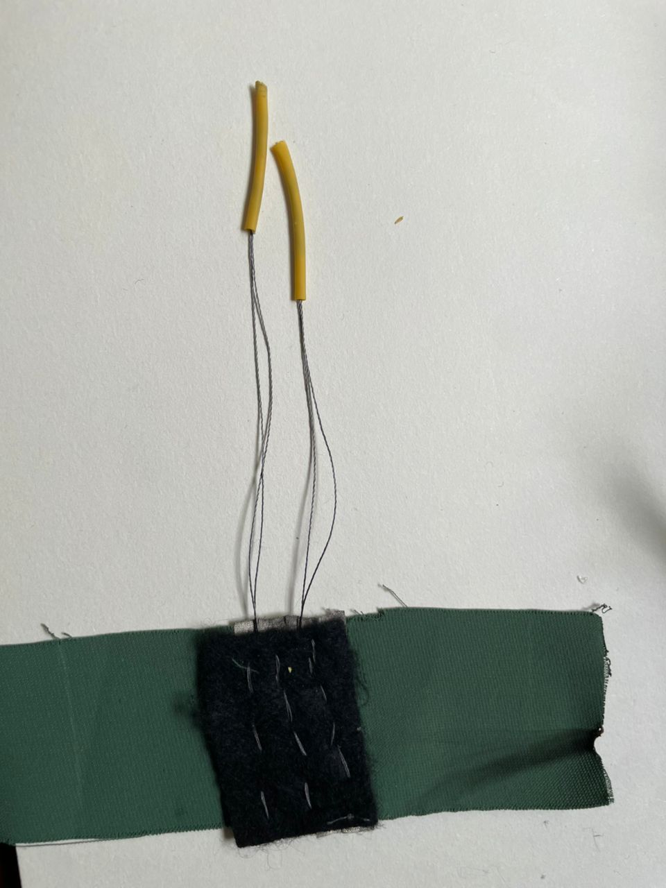
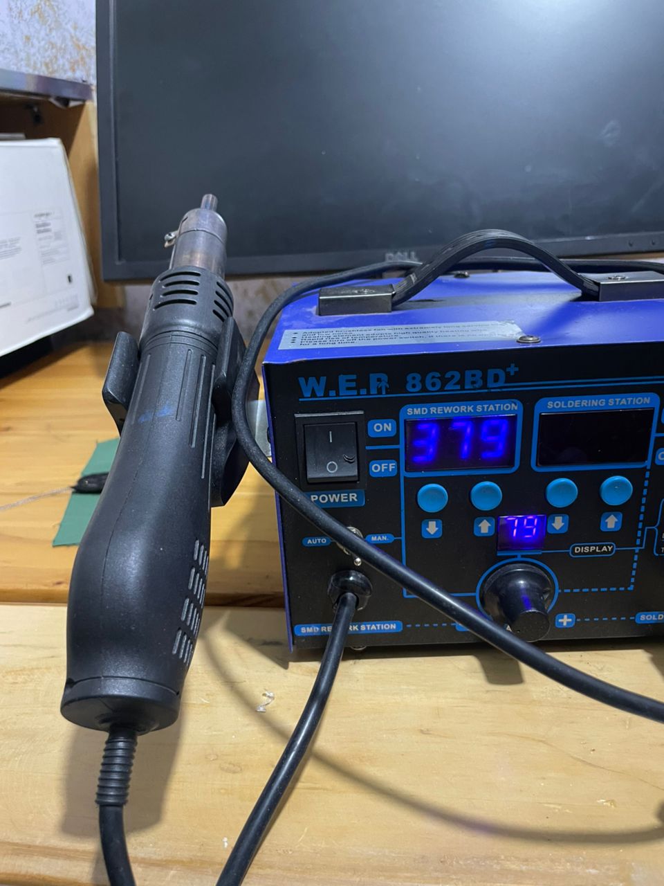
I used a soldering iron to electrically and mechanically secure male header pins to the copper wires, ensuring stable conductive connections. Additionally, a hot air gun was applied to heat-shrink tubing, causing it to contract tightly around the joints to provide insulation, strain relief, and improved durability.
Step 6: Slide a finger through it and feel the size
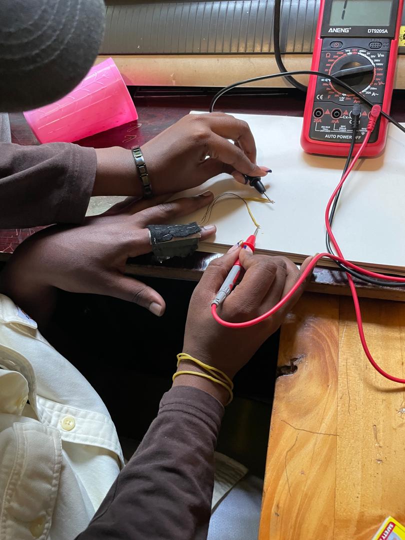
Step7: How to test it
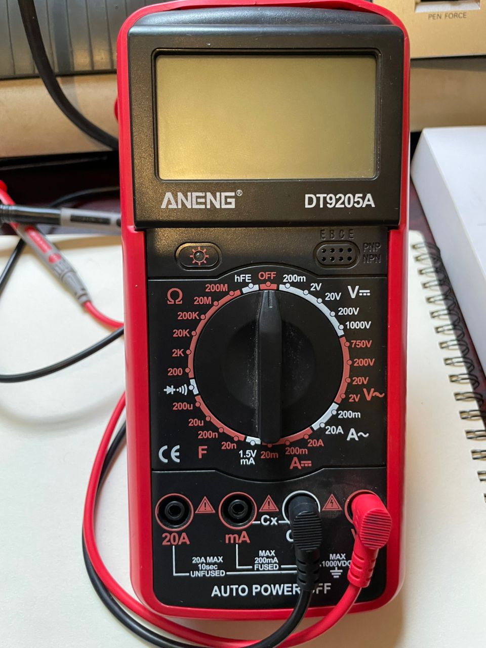
To verify the integrity and conductivity of the copper wires, I used a digital multimeter set to continuity and resistance measurement modes. First, the probes were placed at both ends of each wire to perform a continuity test; an audible beep and near-zero resistance reading confirmed an uninterrupted conductive path. I then measured resistance quantitatively to ensure the values were within an acceptable low range, indicating minimal signal loss. In cases where no continuity was detected or resistance was abnormally high, the wire or solder joint was identified as faulty and reworked. This process ensured reliable electrical connections and overall circuit functionality.
Code Example
Use the three backticks to separate code.
// the setup function runs once when you press reset or power the board
void setup() {
  // initialize digital pin LED_BUILTIN as an output.
  pinMode(LED_BUILTIN, OUTPUT);
}

// the loop function runs over and over again forever
void loop() {
  digitalWrite(LED_BUILTIN, HIGH);   // turn the LED on (HIGH is the voltage level)
  delay(1000);                       // wait for a second
  digitalWrite(LED_BUILTIN, LOW);    // turn the LED off by making the voltage LOW
  delay(1000);                       // wait for a second
}
Results

Video
From Vimeo
Sound Waves from George Gally (Radarboy) on Vimeo.