10. Wearables
November 23rd, 2020
Liza Stark
This second class on the topic of wearables and e-textiles will provide a more advanced coverage on soft sensors and actuators and programming interactions
Research
Useful links
[mosfet and transistor dronwbotworkshop] (https://www.youtube.com/watch?v=IG5vw6P9iY4)
(Capítulo 45 - MOSFET IRF520N módulo transistor de potencia (y PWM)) [https://www.youtube.com/watch?v=SliUieh2eVc]
Tutorial Activities
Program Attiny 85
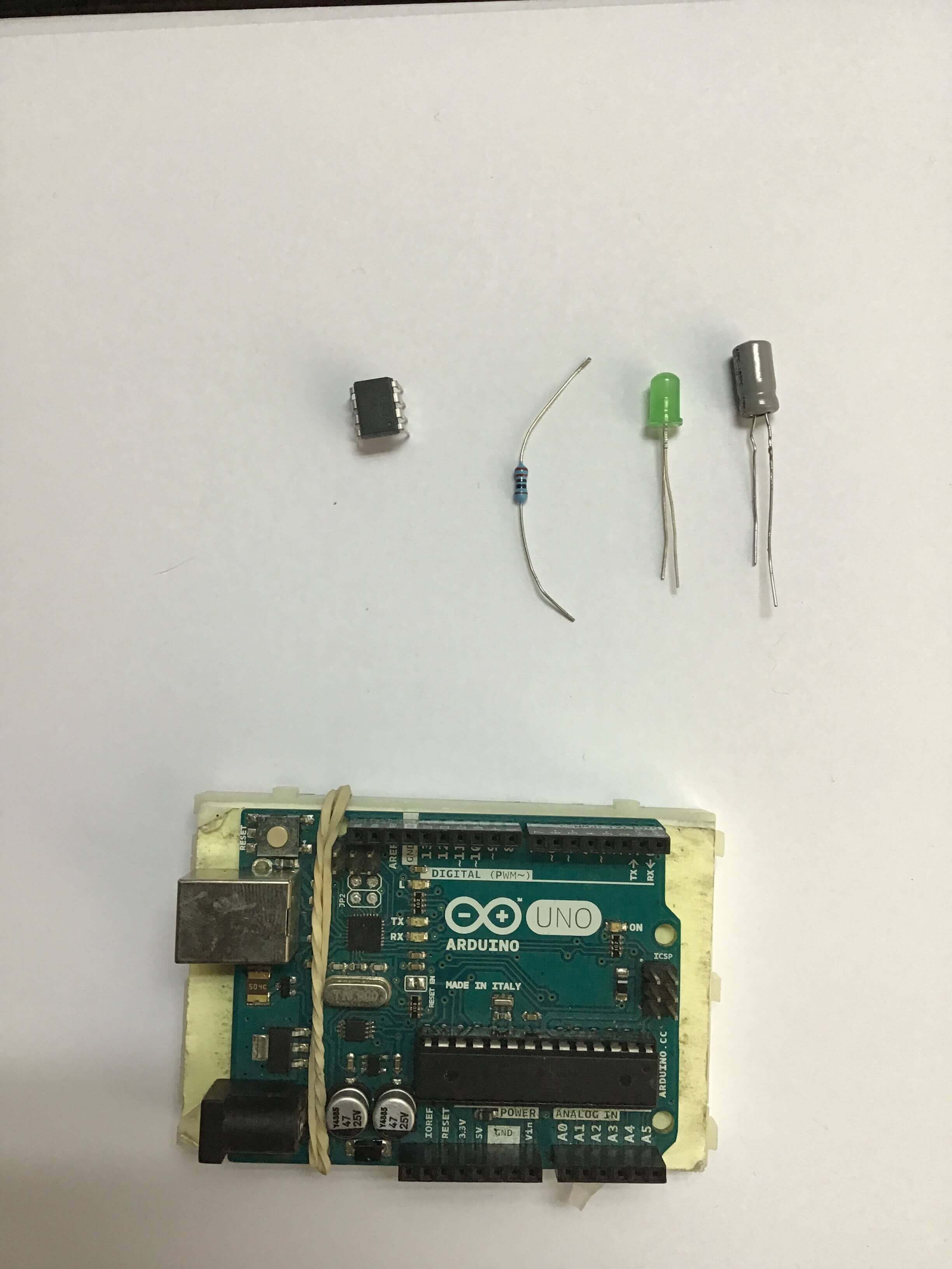
In order to prorgam the Attiny 85, I first required a couple of things: * Attiny85 * Arduino Uno * 1o uf Capacitor * led * 220 ohm Resistance
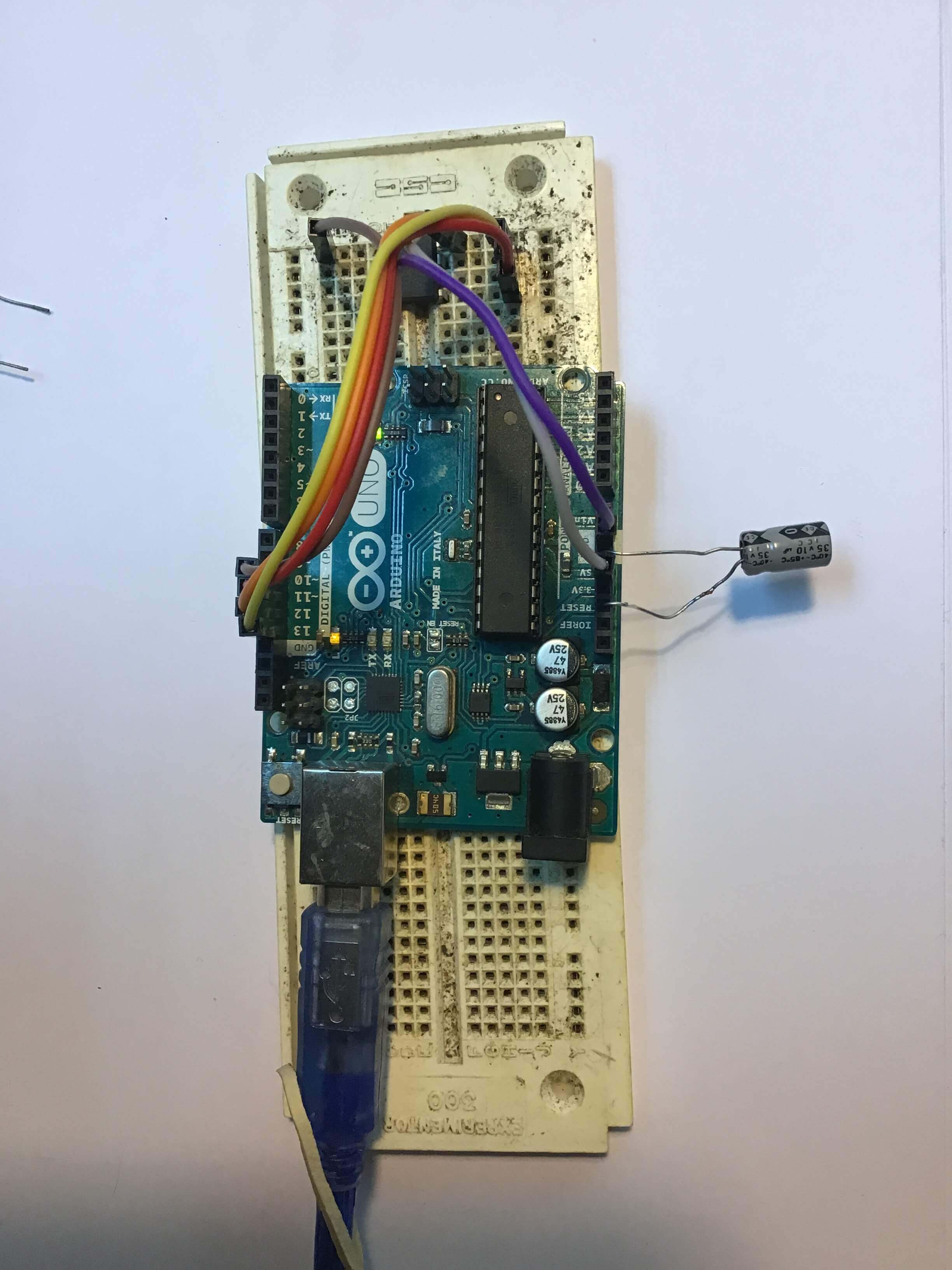
1.1 Setup
In this case I followed the Tutorial on programming attiny Recomended, as well as look over the tutorial on the fabclass.
 I also found the following article usefull as a general purpose article to better undersatnd what is going on. [Arduino as ISP and Arduino Bootloaders] (https://www.arduino.cc/en/Tutorial/BuiltInExamples/ArduinoISP).
1.2 Upload the code
In this instance I uploaded the blink code to test out.
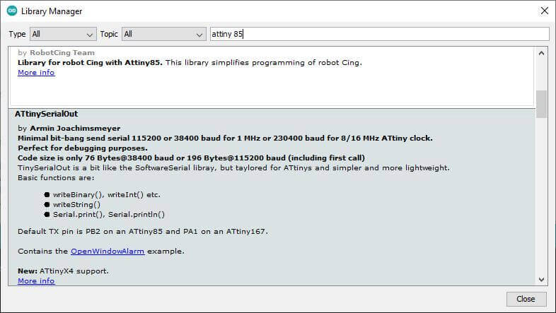
* The library of the attiny85 was installed
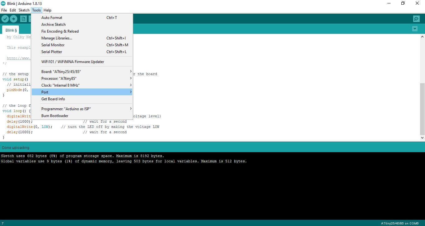
 * The parameters to fit the specifically attiny 85 as follows:
- The programming itself is as follows. The standard Blink example with the led pin changed to '0'.
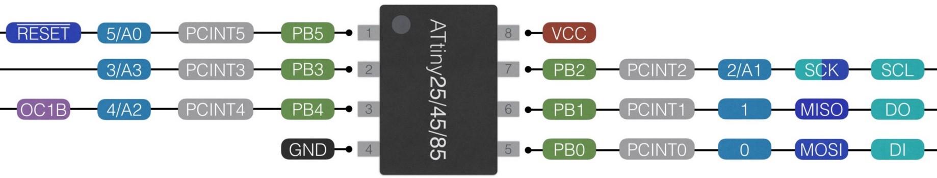
// the setup function runs once when you press reset or power the board void setup() { // initialize digital pin LED_BUILTIN as an output. pinMode(0, OUTPUT); } // the loop function runs over and over again forever void loop() { digitalWrite(0, HIGH); // turn the LED on (HIGH is the voltage level) delay(1000); // wait for a second digitalWrite(0, LOW); // turn the LED off by making the voltage LOW delay(1000); // wait for a second } - Referencial Diagram of Pinout of the Attiny 85:
The end result, for simplicity I decided to use a cr2032 in the breadboard.
TA-w10-1 from mr.jsnap on Vimeo.
Undestanding Mosfets
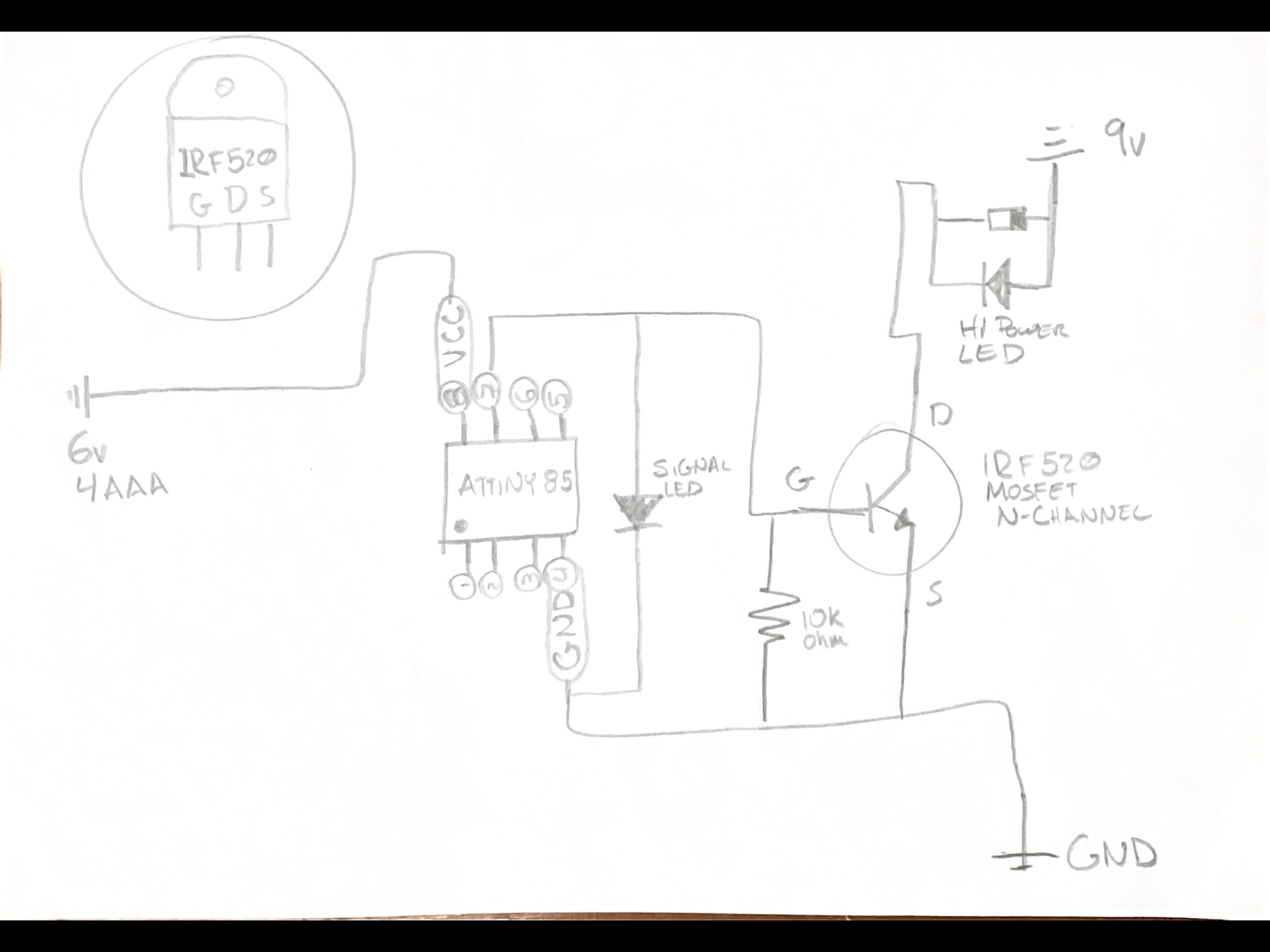
- We saw this part in the tutorial of the week, so I wont go into too much detail. In this case I used the irf520 Mosfet. It is an N-channel Mosfet. Further information is found the IRF520 Datasheet

Apllication of Mosfet: High power LED
In this case I decided to use:
* High Intensity LED
* 9 v battery for The high intensity LED
* 4 AAA Batteries to Power the Attiny, Connected in parallel to create a total volt of 6v, Attiny works up to 5.5v
* 10k ohm resistor
* Diode for High Intensity LED
* Attiny 85, with basic "blink code"
* The connection was follows:
 The code used is:
// the setup function runs once when you press reset or power the board
void setup() {
  // initialize digital pin LED_BUILTIN as an output.
  pinMode(2, OUTPUT);
}

// the loop function runs over and over again forever
void loop() {
  analogWrite(2, 255);   // turn the LED on (255 is the voltage level)
  delay(1000);                       // wait for a second
  analogWrite(2, 0);    // turn the LED off by making the voltage 0
  delay(1000);                       // wait for a second
}
ta-w10-21 from mr.jsnap on Vimeo.
The final goal was to make the entire circuit independent so it works on portable power alone. With this we can test it with the swatches.
- Swatch: One input and one Output. The following is a setup, using a similar setup as before. The great difference is I am using the previously done soft sensor and a pull up input.
- the led will change from off to midway on, to full On.
- The input pullup pin is pin 1
int sw_pin = 1;
int conutner_reset = 3; //how many times we press before we reset

int led_pin = 0; // pin of the led

//variables will change:
int coutner = 0;
int sw_status = 0;
int last_sw_status = 1;


void setup() {
  // initialize input and output pin:
  pinMode(sw_pin, INPUT_PULLUP);
  pinMode(led_pin, OUTPUT);

}

void loop() {
  // put your main code here, to run repeatedly:
  sw_status = digitalRead(sw_pin);

  //compare the switch to its previous state
  if(sw_status != last_sw_status){

    if(sw_status == HIGH){
      coutner = coutner + 1 ;
    }
      delay(10);
  }


  last_sw_status = sw_status;

  if (coutner == conutner_reset){
    coutner = 0; // set the counter to zero again
  }

  if(coutner == 0){
    analogWrite(led_pin, 0); //led is off
  } else if(coutner == 1){
    analogWrite(led_pin, 50);//led is on half way
    delay(100);
  } else if(coutner == 2){.
    analogWrite(led_pin, 255); //led is full on
    }

  }
ta-w10-3 from mr.jsnap on Vimeo.
Generate Sound
Generate Sound with Arduino
In this case, we used:
- IRF520 Mosfet
- 9v battery
- 3w Speaker
- Arduino
Along with the tutorial reviewed in class.
The code:
const int speaker = 3; //buzzer to arduino pin 8
void setup() {
  pinMode(speaker, OUTPUT); // Set buzzer - pin 8 as an Output
}

void loop() {
  tone(speaker, 1000); //send 1khx dounf signal
  delay(1000);
  noTone(speaker);
  delay(1000);
}
The final Result was as follows:
Play Music of Device on Speaker
The same excersice was done as with the arduino, with the modification of using a 1.8mm White Swade leather. The conductive thread was sawn with machine on top, and the speaker used 3 20mm round Rare earth magnets, two under the speaker and one to hold the other two in place. as follows:
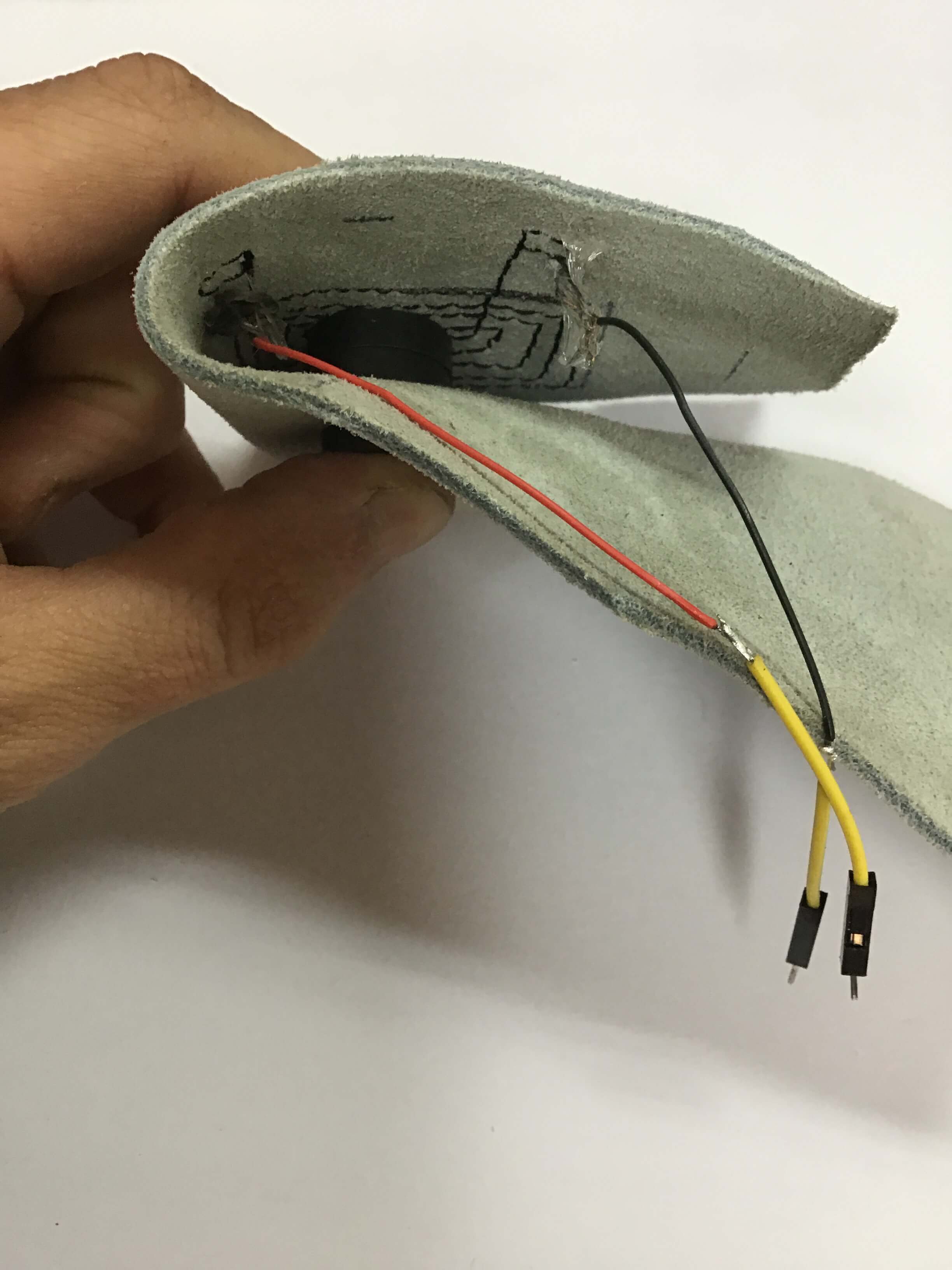
What became interesting is by folding the swade on itself it actually becomes the tension in order to create sound.