12. Skin Electronics
Week 12 | Our Final week! Exploring wearable electronics that are specifically to be placed on the skin.

• • •
Introduction
Assignment
- Document the concept, sketches, references also to artistic and scientific publications
- Design a “skin-circuit”, exploring the replication of the examples below 1. the Skin masquerade party project 2. the Twinkle Nails project 3. interactive tattoo 4. or explore how to create a new skin electronics accessory.
- Document the project and included all source files and all materials used
- Upload your design files and source code
- Make a video with your skin electronic working
- Make a short performance/concept of your project functioning (extra credit)
I was interested in the potential applications of this week especially with the collaboration between the biotech/tech companies and skin professionals such as makeup artists, prosthesis experts and tattooists in order to embrace the idea of human-device symbiosis. The idea of self-healing, biodegradable and reusable materials really caught my attention.
Inspiration
★࿐࿔Alumni: ★࿐࿔
★࿐࿔The Wider World!: ★࿐࿔
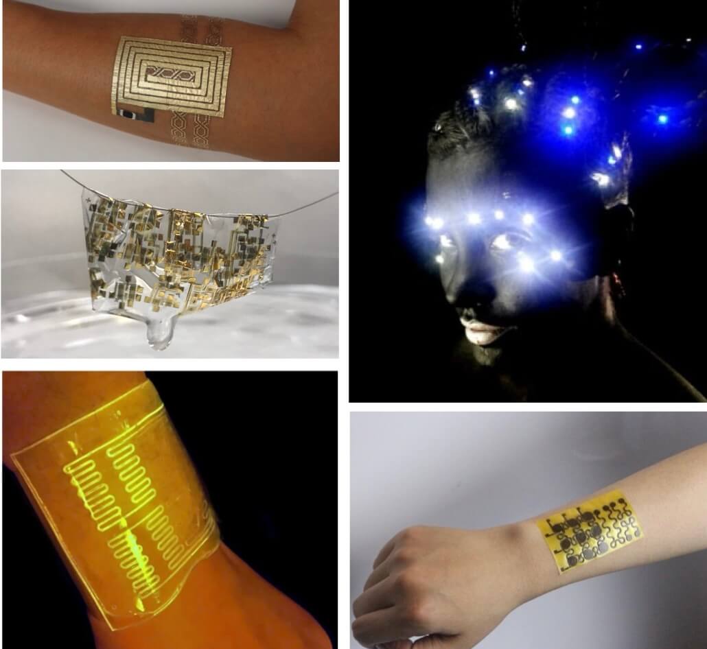
1Photo by DuoSkin on "DuoSkin" | 2Photo by Dezeen on "Biodegradable, Biocompatible Electronic Skin That Dissolves Into The Body" | 3Photo by "Live Science" on "Glowing Gloves" | 4Photo by "Katia Vega" on "KINISI" | 5Photo by "News Atlas" on "Electronic Healing Skin"
DuoSkin is a fabrication process that enables anyone to create customized functional devices that can be attached directly on their skin. Using gold metal leaf, they demonstrate three types of on-skin interfaces: sensing touch input, displaying output, and wireless communication.
A temporary tattoo that can both monitor a person’s progress during exercise and produce power from their perspiration. The device works by detecting and responding to lactate, which is naturally present in sweat.
E-skin is made from polyimine that's been doped with silver nanoparticles. Polyamine allows the e-skin to be both self-healing and fully recyclable at room temperature. At the end of its operational life, the e-skin can be soaked in the ethanol solution, which causes the polymers to degrade and the silver nanoparticles to sink to the bottom.
While the organic electronic circuits are made from iron – chosen because of its non-toxic properties – the thin film substrate was developed from cellulose. This allows the electronics to be worn on the skin and potentially implanted inside the body, subject to further testing. The main drawback of these polymers is the relatively low electrical performance compared with traditional silicon based electronics.
A "living material" - a hydrogel filled with E. coli bacteria cells - that will light up when in contact with certain chemicals, embedded into a skin like plastic. The cells are genetically reprogrammed to light up, using fluorescence, when they come into contact with different chemicals.
Researchers have achieved what they believe to be the first demonstration of a multi-layer, thin film sensor that automatically realigns during healing.
Our global lecture this week was given by Katia who created Kinisi, a FX e-makeup application. Kinisi tries to answer the question: "Could your skin act as an interface?". Different muscle movements such as a smile, a wink, raising an eyebrow or closing the lips will trigger different light patterns.
• • •
Tools
-
Arduino IDE
-
Adafruit Flora Microcontroller
-
Tinker CAD
• • •
Capacitive Sensors
Our electronics tutorials this week focused on creating Capacitor and Potentiometer based sensors.
Capacitive touch sensors store an electrical charge that varies when in touch with another material. Using Arduino IDE and our Flora's again, we created a circuit to display the values that the sensor reads when the capacitive material is touched.

Equipment
-
Medical Tape
-
Copper Tape
-
Kapton Tape
-
2 x Crocodile Clips
-
1 MΩ Resistor
-
Adafruit Flora
With Citlali's help we were walked through how to code our Flora's to light up the internal LED when a threshold pressure value was exceeded when the copper tape was touched.
#include <Adafruit_NeoPixel.h>

#include <CapacitiveSensor.h>

CapacitiveSensor sensor = CapacitiveSensor(10,9); //1M ohm resistor between pin 9 and 10

#define PIN 8

#define NUMPIXELS 1

Adafruit_NeoPixel pixels(NUMPIXELS, PIN, NEO_RGB + NEO_KHZ800);

#define DELAYVAL 500

void setup() {
  Serial.begin(115200);
  pixels.begin();   // initialise neopixel object

}

void loop() {
  long measurement = sensor.capacitiveSensor(30);

  Serial.println(measurement);
  delay(10);

  if (measurement >500) {   //threshold value
    pixels.clear();     //set my pixels colours to 'off'
    // pixels.Color() takes RGB values, from 0,0,0 up to 255,255,255
    // here we're using a moderately bright green colour;
    pixels.setPixelColor(0, pixels.Color(0,150,0));
    pixels.show();  //send the updated pixel colours to the hardware
    //delay(DELAYVAL); // pause before next pass through loop
  } else {
    pixels.clear();   // set my pixel colours to 'off'
    pixels.setPixelColor(0, pixels.Color(0,0,0));   // r,g,b in 0 means black
    pixels.show();    // send the updated pixel colours to the hardware
  }

}
★࿐࿔
★࿐࿔
Below are the readings collected on the Arduino Serial Monitor when the sensor is touched.
• • •
Potentiometer Sensors
Potentiometers are a type of position sensor, they are used to measure displacement in any direction. Citlali showed us how to create a DIY Potentiometer sensor with the layout and components below.
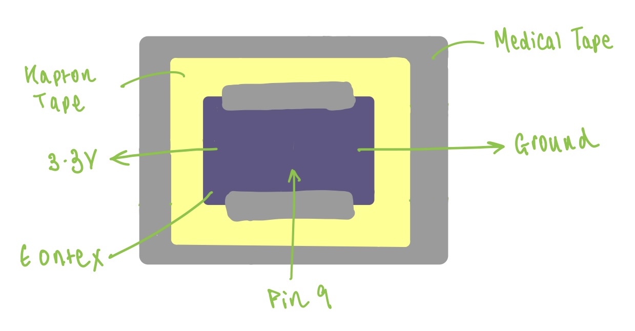
Equipment
-
Medical Tape
-
Copper Tape
-
Kapton Tape
-
Eontex
-
3 x Crocodile Clips
-
Adafruit Flora
This piece of code changes the brightness of the Flora's internal LED depending on the distance of the crocodile clip from the beginning of the eontex strip.
#include <Adafruit_NeoPixel.h>
#include <CapacitiveSensor.h>

CapacitiveSensor sensor = CapacitiveSensor(10,9); //1M ohm resistor between pin 9 and 10

#define PIN 8
#define NUMPIXELS 1

Adafruit_NeoPixel pixels(NUMPIXELS, PIN, NEO_RGB + NEO_KHZ800);

#define DELAYVAL 500


int potentiometer=A9;
int value;
int valMap;

void setup() {
  pinMode(potentiometer, INPUT);
  Serial.begin(9600);
  pixels.begin();

}

void loop() {
  value=analogRead(potentiometer);
  valMap = map(value, 50, 400, 0, 255);
  //print out the value you read
  Serial.println(value);
  delay(1); //delay inbetween reads for stability
  pixels.clear();
  pixels.setPixelColor(0, pixels.Color(0, valMap, 0));
  pixels.show();

}
★࿐࿔
★࿐࿔
Below is the readings collected on the Arduino Serial Monitor when the crocodile clip moves along the sensor, producing a range of values.
• • •
LED Snake Bracelet
A few of my initial ideas for this week included creating a DIY mood ring, electronic grillz, thermochromic tattoos or an LED bracelet potentially connected to a ring. I chose to explore the latter, and take inspiration from Stephanie's project.
I first drew out a basic design of how I thought I could mould the wire to look like a snake's head, and integrate the coincell battery. Originally I wanted red SMDs for the eyes and white for the scales down the body, but this required me adding a few resistors. I decided to make all the SMDs white and colour with red pen the 'eye' SMDs.

Schematic Diagram
Using TinkerCAD I drew out the schematic diagram which was simply 11 SMDs in parallel to the coin cell battery. TinkerCAD didn't have SMDs in its library so I used LEDs for the diagram instead.
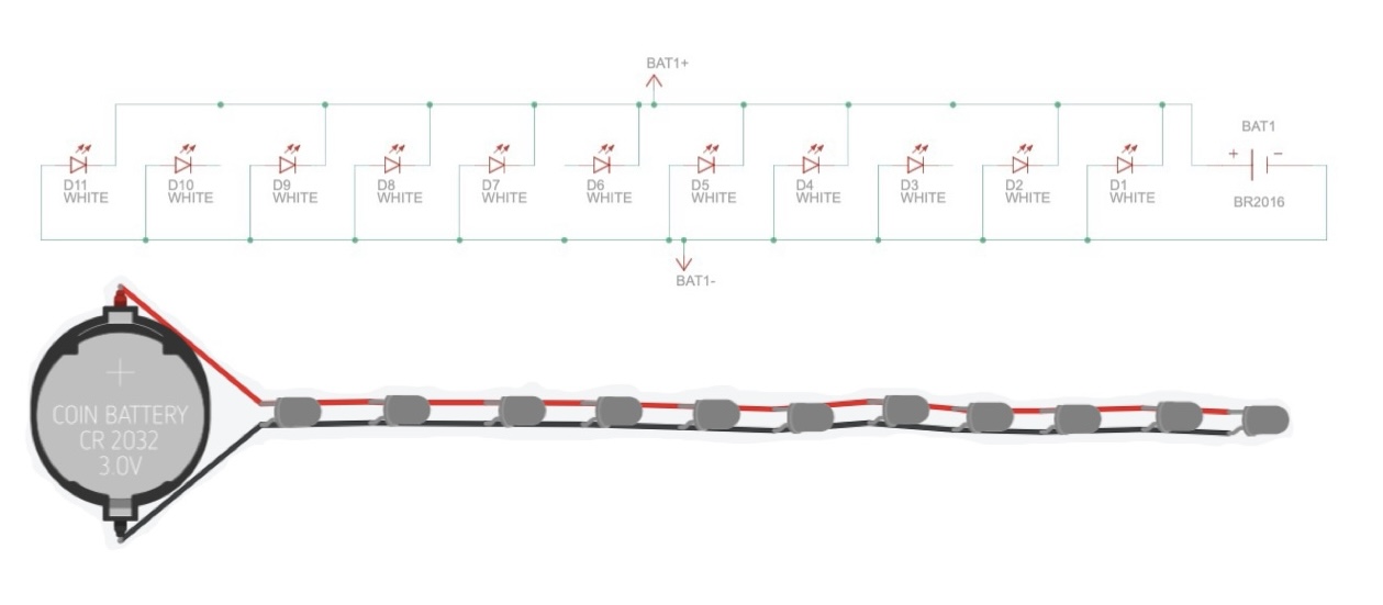
Assembly
The assembly was so fidly as SMDs are tiny and can break off of soulder very easily, so it took many tries for the bracelet to actually work.
Equipment
-
Brass Wire
-
Wire Cutters
-
11 White SMD LEDs (Surface Mounting Diode)
-
Solder and Soldering Iron
-
Coincell Battery and Battery Holder
I made the shape of the snake that I wanted and threaded the coin-cell battery holder into place by the head. The next steps were simply to solder the SMDs making sure that they are connected in the right direction to the positive and negative wires.
TIP!
Make sure that the wires are not crossing over or touching anywhere as this will cause a short circuit.
I tested the circuit on a power supply with 3.3V to check the connections, all the lights shone very brightly!
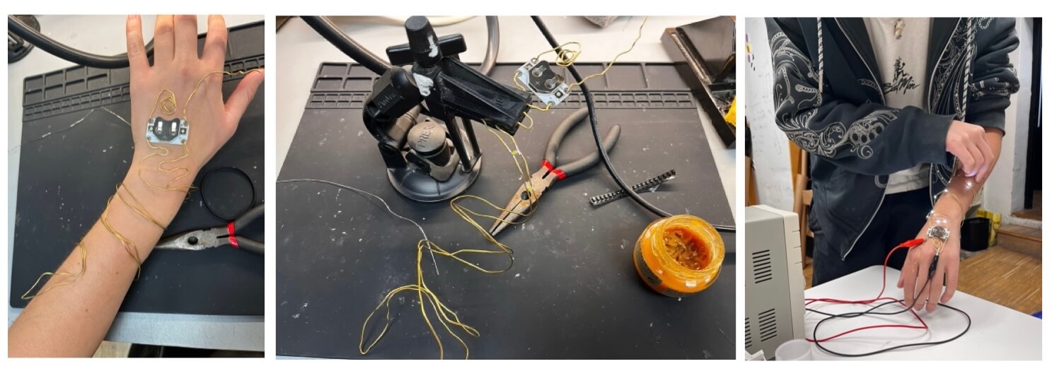
Left: Molding the wire, Centre: Soldering the SMDs, Right: Testing the circuit on a power supply
I also tested the eyes with the red SMDs, however without a resistor they pulled all the voltage from the white SMDs.
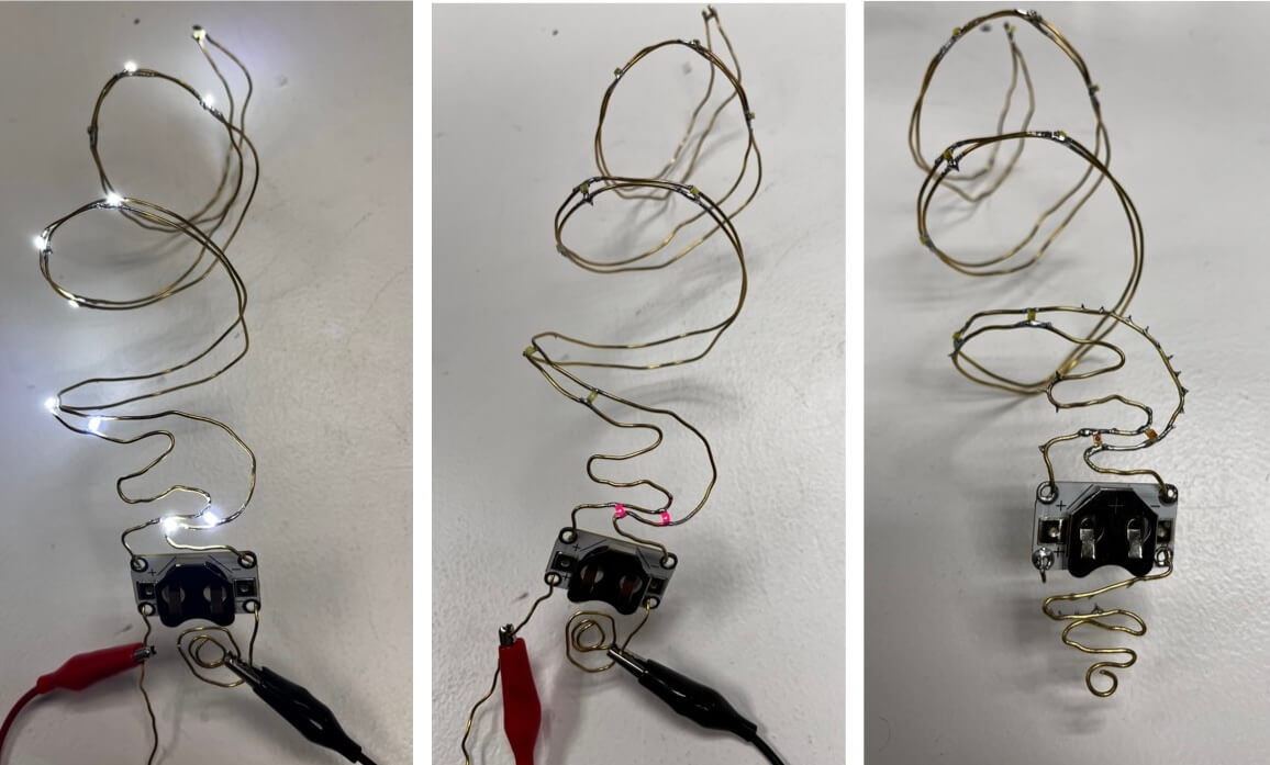
Left: all white SMDs shining, Centre: Red SMDs pulling all the voltage, Right: Final wire nose configuration
Results
The final result was cute and was what I expected but it was alot more fragile and vulnerable than I thought. You have to wrap it around the wrist very carefully to avoid the SMDs snapping off. The wires are very easily pushed together so when you place the coin cell battery into the holder the lights sometimes go off as the circuit is shorted. I would also like to incorporate the red SMDs in the future as it definitely makes a difference in separating the eyes from the snake's body.
I didn't have time to add the ring although it would have been a nice combination with the bracelet.

Whilst moving around the circuit obviously short circuited but it provided a way to see how the piece would look if I had incorporated a micro-controller to flash/fade the SMDs.