12. S K I N _ E L E C T R O N I C S
C Y B O R G _ C H I C
I N S P I R A T I O N
This week I was inspired by the F A C E -> looking at structure + adornment + masking + moulding

Pablo Picasso + Picasso face game
- Here I was interested in the facial symmetry / lack of + composition
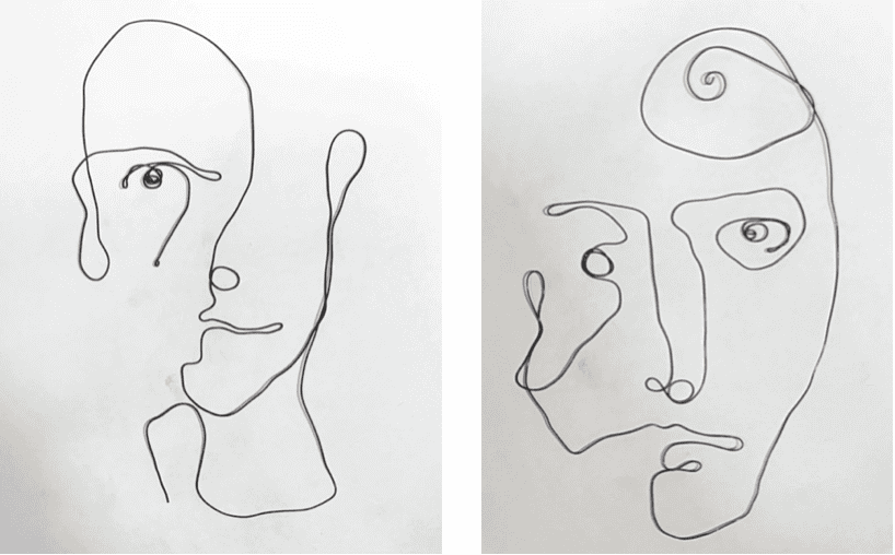
Frank Marino Baker Wire Artist and Sculptor
- I find the simplicity + elegant flow of the wire drawings mesmerising. Such minimal lines convey so much detail.
I'm always inspired by continuous line drawings, & wire is one of the best ways to do this.
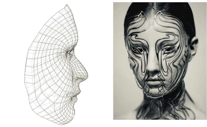
Iris Van Herpen Mask
-
For this mask a 3D scan of the wearer’s face was input into a design program running the Grasshopper algorithm, which combined colour information with the 3D model to generate a “semi-arbitrary density structure” that was mapped to the face.
-
I am interested in mapping and following the structure + contours of the face

Gabriella Mika Goldsmith Danish jewellery designer
- I admire the exploration of the face in jewellery and the surrealist approach

Ruby Mellish Contemporary Jewellery Designer
- I like the use of illusion in this work and how delicate the pieces are.
Further inspiration =
Hanne Keklaver for facial expression, movement & fun !
R E S E A R C H
Liza Stark Wearables Slideshow to catch up on some electronics
Emma Pareschi Tutorial for ATtiny + Capactive Sensor tutorial
M A T E R I A L S
Used materials
Multimeter, Soldering iron, Conductive Materials, Arduino Uno, ATtiny, Gemma, Aligator clips, wire, wire strippers/cutters, battery packs, SMD LED's, NeoPixels
Other materials
Shape memory alloys (SMAs), latex, fake nails, masks, optic fibers, arduino nano board, resistors, capacitors
M I C R O N T R O L L E R
Examples of AVR Microcontroller
- Arduino Uno (ATmega328)
- Attiny 44, 84
- Attiny 45, 85
A T t i n y
Refer back to Wearables Week 08 on more in depth: How to program an ATtiny
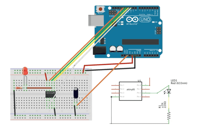
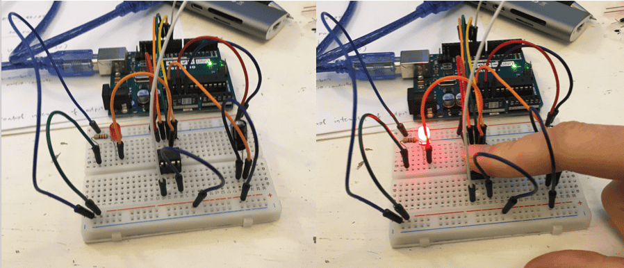
Schematic of Programming ATtiny using Arduino Uno
NOTE = Capacitor short leg to ground
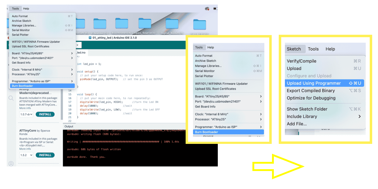
Settings for ATtiny in Arduino IDE
- Board: ATtiny 25/45/85
- Port : Select port you are using
- Clock: Internal 8 MHz
- Processor:ATtiny 25
- Programmer: Arduino as ISP
Select Burn Bootloader
CODE = LED BLINK
int led_pin = 1;

void setup() {
// put your setup code here, to run once:
pinMode(led_pin, OUTPUT);   // set the pin 3 as OUTPUT

}

void loop() {
// put your main code here, to run repeatedly:
digitalWrite(led_pin, HIGH);      //turn the Led ON
delay(1000);                //wait
digitalWrite(led_pin, LOW);       //turn the Led OFF
delay(1000);                //wait
}
Select Sketch -> Upload Using Programer
NOTE = At first programming the Attiny did not work for me and the LED did not blink.
After some trial & error, I realised this was due to Attiny not pushed down into socket deep enough to get connection. I pushed the Attiny down into the breadboard and it worked !
G E M M A
How to program and use an ADAFRIUT GEMMA
NOTE
- Do not mix up with Arduino Gemma
- Ensure Gemma cable includes DATA and capable of programming
- Upload Adafruit Gemma Board
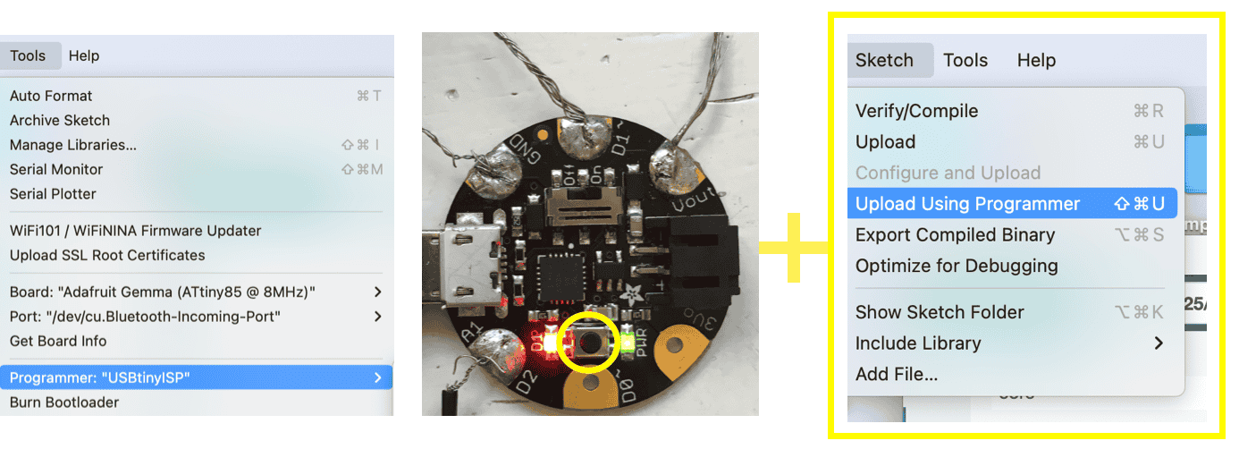
Settings for Gemma in Arduino IDE
- Board: Adafruit Gemma (ATtiny85 @ 8MHz)
- Port : Select port you are using
- Programmer: USBtinyISP
Press button (between lights) just before Upload Using Programmer
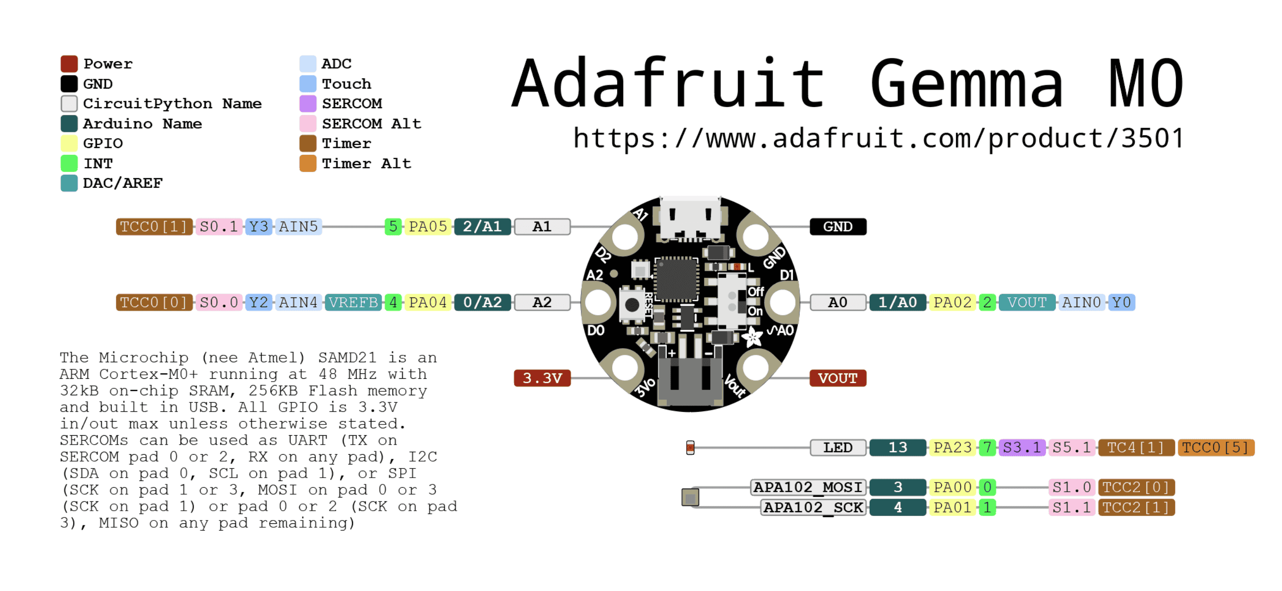
Adafruit Gemma M0 Pinouts information
How to Program Adafruit Gemma V2
MPR121 I2C
MPR121 Breakout V12 Capacitive Touch Sensor Controller Module I2C Keyboard Module
The MPR121 is a capacitive touch sensor controller driven by an I2C interface. The chip can control up to twelve individual electrodes, as well as a simulated thirteenth electrode. The MPR121 also features eight LED driving pins. When these pins are not configured, they may be used to drive LEDs. There are four jumpers on the bottom of the board, all of which are set (closed) by default.
MPR121 GPIO and LED Driver Function
Connecting pins for AdaFruit Gemma and MPR121 I2C
                            Gemma  ->   MPR121 I2C

                            3V            VIN
                            GND           GND
                            D0            SDA
                            A1            SCL
Download Adafruit_MPR121 library
Sketch -> Include Library -> Manage Libraries -> Seach for Adafruit_MPR121 library -> Install
Load Demo -> File -> Examples -> Adafruit_MPR121 -> MPR121test -> Upload to Arduino wired up to sensor
CODE : DID NOT WORK
Modified MPR121test code (command out all Serial)
Code kept reading = Compilation error: exit status 1
I decided to leave this as it seemed there was an incompatibility issue with library dependencies and the gemma with the MPR121 I2C. If I were to try and use the MPR121 I2C again in the future, I would try another microcontroller.
TUTORIALS
Adafruit MPR121 12-Key Capacitive Touch Sensor Breakout Tutorial
Adafruit MPR121 12-Key Capacitive Touch Sensor Breakout Tutorial Arduino + Wiring guide
Adafruit MPR121 12-Key Capacitive Touch Sensor Breakout Tutorial PDF version
How to connect Arduino Gemma to Capacitive touch Sensor
MPR121 GPIO and LED Driver Function
EXAMPLES
Some Examples of MPR121 Capacitive Touch Sensor working
MPR121 turn (almost) any surface to a touch button for Arduino
Making a piano with MPR121 Capacitive Touch Sensor
M A S K
I decided that I wanted to make a mask modelled on my face. My initial design was very personal and in some ways a self portrait.
D E S I G N
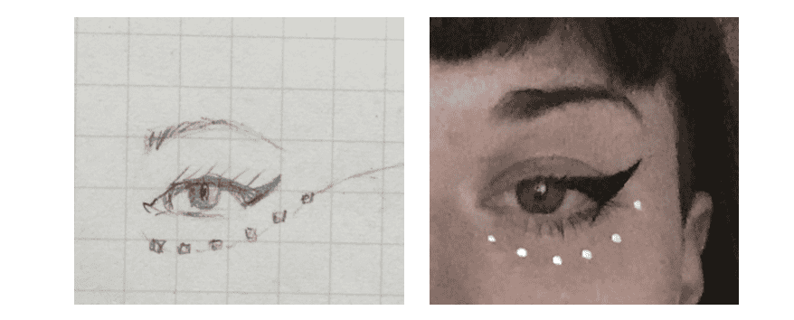
A signature & personal favourite of my makeup is adding little white dots under my eyes.
I wanted to use this in my design and illuminate them.
P R O C E S S
M A K I N G _ S M D _ L E D _ D O T S
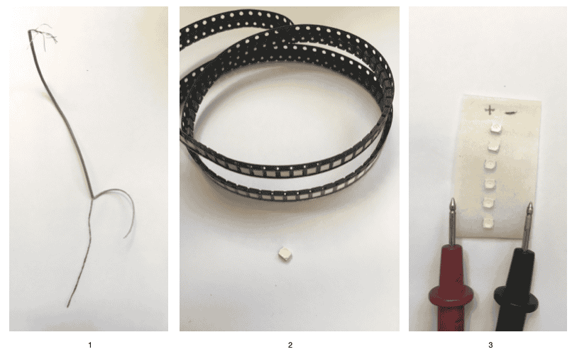
Step 1 - Strip wire (I liked the bare chrome look)
Step 2 - I decided to use SMD LEDs (Surface Mount Device Light Emitting Diode) as they were the perfect size
Step 3 - Use multimeter to test which is possitive & negative side (will light up)
NOTE
- To keep track of SMD LED's I stuck them onto some tape and made a note of possitive & negative sides.
_1 Drawing to indicate design & direction of circuit
__2 Conductive wire soldered to 6 SMD LED's either side
___3 Schematic diagram of design with 3V battery
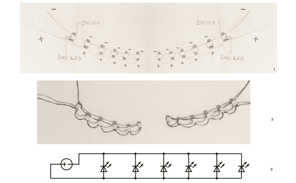
Testing the soldered circuit with a 3V battery I T _ W O R K S !
M A K I N G _ M A S K
Instead of camouflaging the circuit, I decided I wanted to integrate it.
I also wanted to incorporate + make use of my lip piercing, I decided to use it as a switch
NOTE - I had to test the conductivity of my lip ring to ensure it would work as a switch
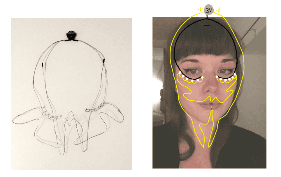
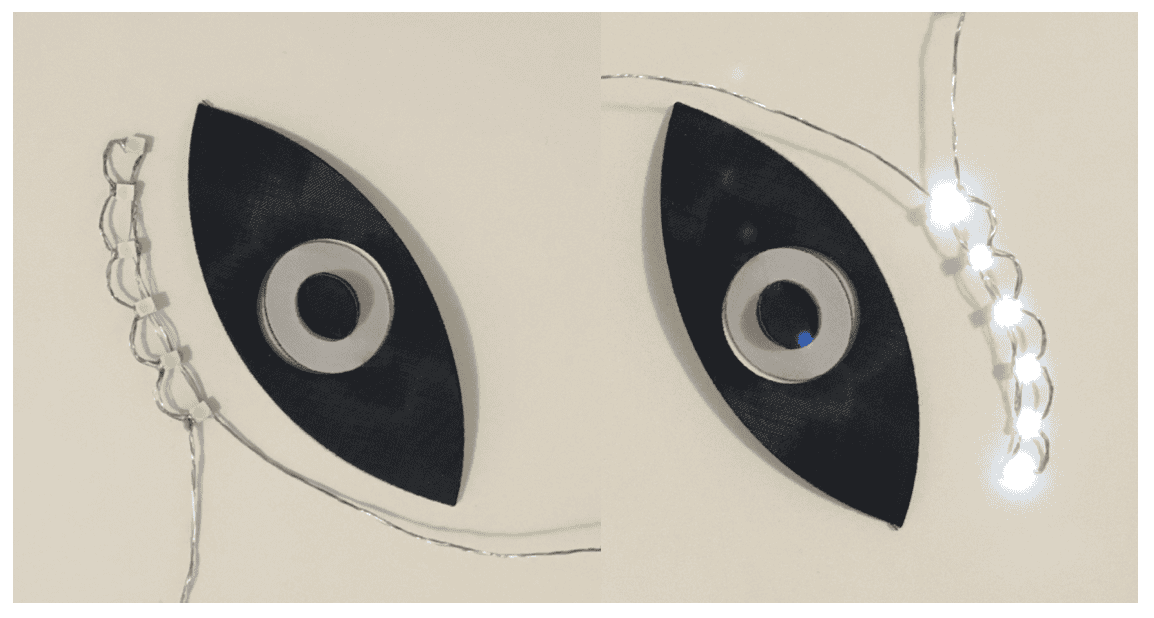
Design & finalised piece
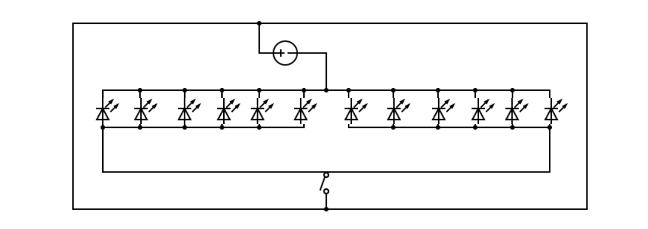
Schematic diagram of circuit
Video showing piece unworn - It works !
R E S U L T
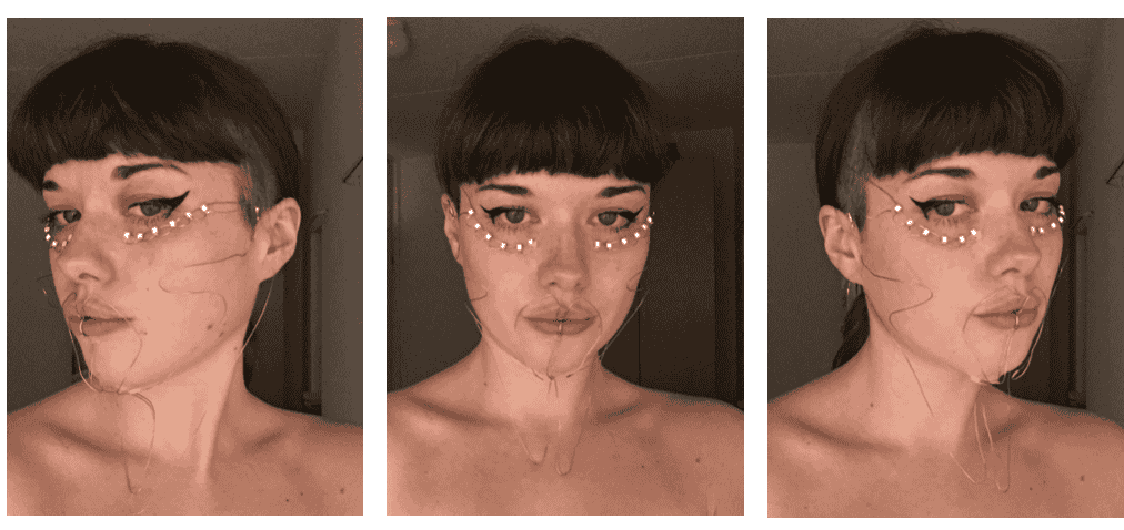
Mask Worn
C O N C L U S I O N
While it works there were a few issues =
-
The lip ring switch works well, however it needs a lot of pressure to close the circuit (its not as smooth of a movement as I would like).
When phycially pressed down, it works very well. -
While the electronics were behaving, the mask itself was quite difficult to put on, attach and mould
-
There was a slight 'buzz' / odd sensation from the lip ring switch (maybe not the best for long periods of time?). This 'buzz' was because I was part of the circuit, and my lips/mouth were wet = meaning the resistance is much lower compared to dry skin. Meaning this sensation was actually the feeling of the current flowing. Further reading about Conduction of Electrical Current to and Through the Human Body: A Review
Things that worked well =
-
While it is simple electronics, I felt it was what the design needed
-
I used coated wires at the battery end of the wires so that if they touched it would avoid a short in the circuit
-
While im still getting to grips with soldering, I was happy with the result of the SMD LEDs attached to the wire as it was delicate work
I am pleased with the result, however I would change a few things =
-
Either make the wire mask more structured and striking, or else only have SMD LED's under the eyes
-
Use an on/off switch (when putting on, the wires hit off eachother and close the circuit intentionally)
-
Add a soft backing to the mask so it is more comfortable on the skin
L D R _ N E O P I X E L
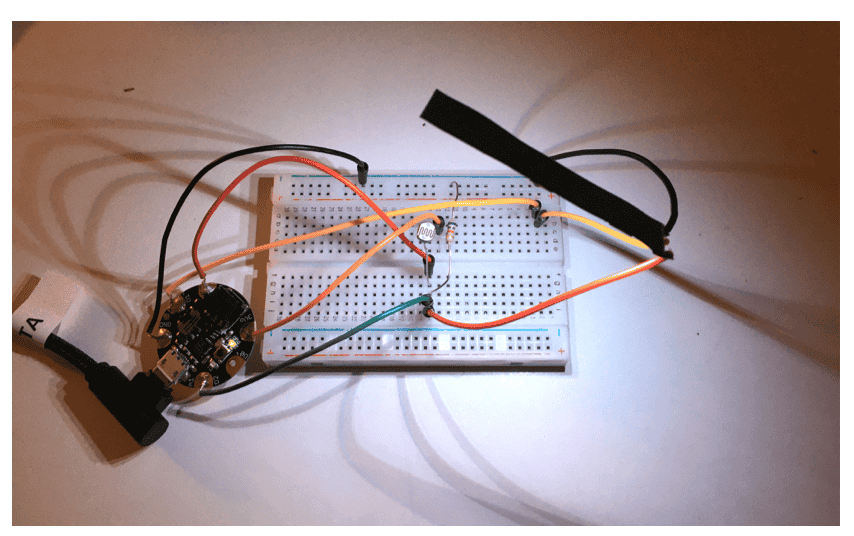
Using a NeoPixel strip, Adafruit Gemma and LDR (light dependent resistor) / Photoresistor
CODE
// Use LDR (photoresistor) to turn on Neopixel when in the dark

//Constants
const int pResistor = 1; // Photoresistor (LDR) at Gemma pin D1
const int ledPin= 2;       // Neopixel pin at Gemma pin 2

//Variables
int value;                // Store value from photoresistor (LDR) (0-1023)

void setup(){
pinMode(ledPin, OUTPUT);  // Set lepPin - 2 pin as an output
pinMode(pResistor, INPUT);// Set pResistor - D1 pin as an input (optional)
}

void loop(){
value = analogRead(pResistor);

//You can change value "25"
if (value > 25){
    digitalWrite(ledPin, LOW);  //Turn led off
}
else{
    digitalWrite(ledPin, HIGH); //Turn led on
}

delay(500); //Small delay
}
Currently Neopixel working, however unresponsive to LDR
Since the Gemma does not read serial, for the future I might be better trying Arduino Nano or Arduino Uno with ATtiny
F U T U R E
-
Further experiment with switches + body movement / interaction = muscle switch body suit
-
Investigate senors further (LDR, capacitive touch)