12. SKIN ELECTRONICS

RESEARCH
This week I continued to build on my knowledge from the previous weeks. During this week we had amazing workshops and tutorial with Citlali Sánchez. I used again Seeed Studio XIAO ESP32C3.
TOOLS
- ELEGOO Electronic Fun Kit
- Software: Arduino IDE
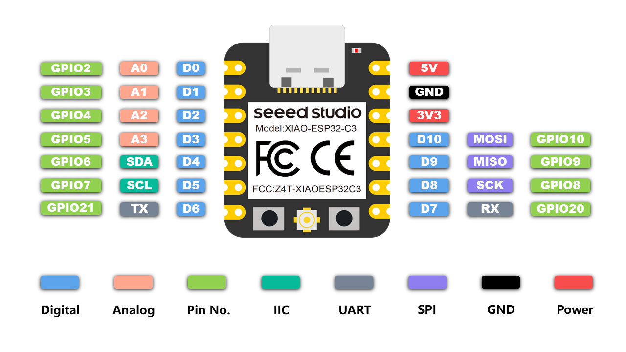
- Hardware: Seeed Studio XIAO ESP32C3
INSPIRATION
After searching through past projects from Fabricademy and conducting general research for skin electronics, I found these projects that resonated with me.
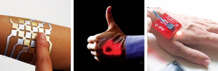
1) DuoSkin - MIT Media Lab 2) The Future of Skin Electronics 3) The microchip implants
SKIN PRESSURE SENSOR
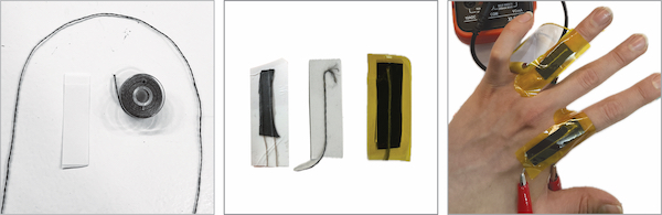
We began the week with a tutorial with Citlali where we made skin pressure sensors and a skin matrix. We also learned about array functions. I started by making the skin pressure sensors using Velostat.
TOOLS - skin pressure sensor
- Conductive thread
- Kapton insulating tapes
- Velostat
- Skin-safe double sided tapes
For the bending sensor, I placed two strands ad of conductive thread on the skin-safe double sided tapes using glue, then placed one strip of velostat. Cut out another piece of skin plaster foil that is the same size as the base foil. Peal off the sticky side backing and place on top of the constructed sensor so they stay in place.
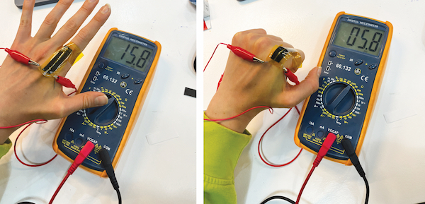
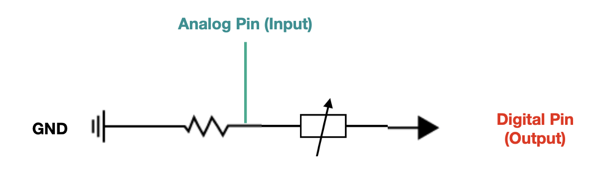
Skin Pressure Sensor CODE
- Code for reading the change in values when bending the finger.
int sensorPin = A0; // select the input pin for the potetntiometer

int sensorValue = 0; // variable to store the value coming from the sensor

int pinD = D8;
int b = 0;


void setup() {
  // declare the ledPin as an OUTPUT:
  pinMode(pinD, OUTPUT);
  pinMode(sensorPin, INPUT);
  Serial.begin(9600);

}

void loop() {
  // read the value from the sensor:
 // b = !b; // asigno el contrario
digitalWrite(pinD, HIGH);
sensorValue = analogRead(sensorPin) ;
Serial.println(sensorValue) ;
delay (200);
}

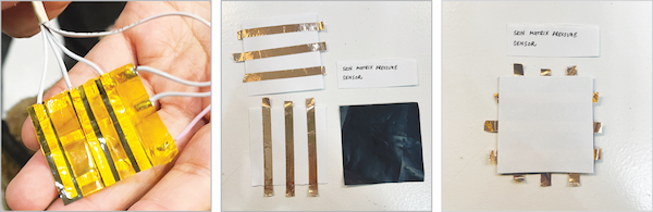
SKIN MATRIX PRESSURE SENSOR
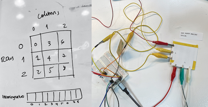
After Citlali explained how the pressure sensor worked, she assisted us in creating the 3x3 matrix consisting of 9 sensor reading points. We began by making the prototype of matrix on paper.
Pressure matrix sensor built from conductive rows and columns with a piezoresistive material - Velostat. The piezoresistive effect refers to the change in electrical resistivity of a material when mechanical strain is applied, and is often observed in metals and semiconductors.
Resources and links
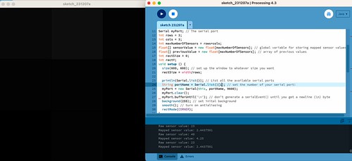
- SOFTWARE - Processing - free graphical library and integrated development environment (IDE). Processing uses Java, with additional classes and functions. It provides a GUI for compiling and executing code.
Skin matrix pressure sensor - Visulaisation in Processing 4.3

/*
Code based on Tom Igoe’s Serial Graphing Sketch
 >> http://wiki.processing.org/w/Tom_Igoe_Interview
 Reads X analog inputs and visualizes them by drawing a grid
 using grayscale shading of each square to represent sensor value.
 >> http://howtogetwhatyouwant.at/
 */

import processing.serial.*;

Serial myPort; // The serial port
int rows = 3;
int cols = 3;
int maxNumberOfSensors = rows*cols;
float[] sensorValue = new float[maxNumberOfSensors]; // global variable for storing mapped sensor values
float[] previousValue = new float[maxNumberOfSensors]; // array of previous values
int rectSize = 0;
int rectY;
void setup () {
  size(600, 600); // set up the window to whatever size you want
  rectSize = width/rows;

  println(Serial.list()); // List all the available serial ports
  String portName = Serial.list()[1]; // set the number of your serial port!
  myPort = new Serial(this, portName, 9600);
  myPort.clear();
  myPort.bufferUntil('\n'); // don’t generate a serialEvent() until you get a newline (\n) byte
  background(255); // set inital background
  smooth(); // turn on antialiasing
  rectMode(CORNER);
}

void draw () {
  for (int i = 0; i < maxNumberOfSensors; i++) {
    fill(sensorValue[i]);
    rect(rectSize * (i%rows), rectY, rectSize, rectSize); //top left
    if ((i+1) % rows == 0) rectY += rectSize;
  }
  rectY=0;
}

void serialEvent(Serial myPort) {
  String inString = myPort.readStringUntil('\n'); // get the ASCII string
  println("test");
  if (inString != null) { // if it’s not empty
    inString = trim(inString); // trim off any whitespace
    int incomingValues[] = int(split(inString, "\t")); // convert to an array of ints

    if (incomingValues.length <= maxNumberOfSensors && incomingValues.length > 0) {
      for (int i = 0; i < incomingValues.length; i++) {
        println("Raw sensor value: " + incomingValues[i]);
        sensorValue[i] = map(incomingValues[i], 0, 2400, 0, 255);
        println("Mapped sensor value: " + sensorValue[i]);
      }
    }
  }
}
CODE Matrix Pressure Sensor - CONTROLLING LED
#define numRows 3
#define numCols 3
#define sensorPoints numRows* numCols

int led = A3;
int rows[] = { A0, A1, A2 };
int cols[] = { 8, 9, 10 };
int incomingValues[sensorPoints] = {};  // this is the array of all the 9 sensors

void setup() {
  for (int i = 0; i < numRows; i++) { pinMode(rows[i], INPUT); }   // so that it can be an input but increasing up to the number of rows that we have in the array
  for (int i = 0; i < numCols; i++) { pinMode(cols[i], OUTPUT); }  // so that it can be an input but increasing up to the number of columns that we have in the array
  Serial.begin(9600);
}

void loop() {
  for (int colCount = 0; colCount < numCols; colCount++) {
    digitalWrite(cols[colCount], HIGH);
    for (int rowCount = 0; rowCount < numRows; rowCount++) {
      incomingValues[colCount * numRows + rowCount] = analogRead(rows[rowCount]);  // it does this function first three times before closing and going to the one outside of it
    }
    digitalWrite(cols[colCount], LOW);  // its reading the one row three times then it turns it off and jumps to the next row
  }
  for (int i = 0; i < sensorPoints; i++) {
    Serial.print(incomingValues[i]);
    if (i < sensorPoints - 1)
      Serial.print("\t");
  }
  Serial.println();
  delay(200);

  int ledMap = map(incomingValues[1], 100, 3500, 0, 255);
  analogWrite(led, ledMap);
}

NFC APPLICATIONS
Resources and links
TOOLS
PRINCIPLE | How does the NFC chip work?
NFC (Near Field Communication) tags do not require a separate power source or battery because they operate based on a principle called inductive coupling.
Passive Operation: NFC tags are generally passive devices, meaning they do not actively generate power. Instead, they rely on the energy provided by an active NFC device, such as a smartphone or NFC reader.
Inductive Coupling: When an NFC-enabled device (like a smartphone) comes close to an NFC tag, the device generates an electromagnetic field. This field induces a current in the coil within the NFC tag, effectively powering it temporarily.
MOTIVATION
I have been following the NFC trend for a while now to understand how it works and what can be done.
The mobile app makes programming and utilizing the NFC chip very easy. My first experience was designing my business card which linked to the Fabricademy website. Here is a little tutorial on how to set up your own chip.
TUTORIAL | How to create NFC link to your website
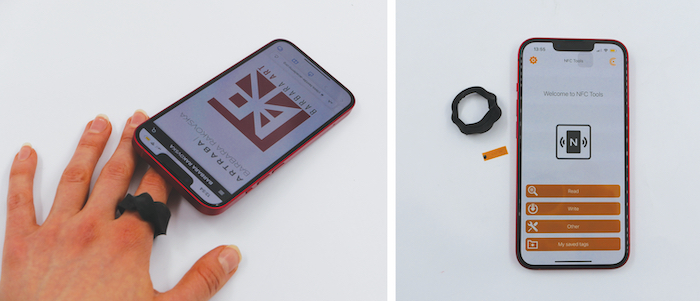
The first step is to install the application for Android or iOS - NFC Tools - App to read and write NFC tags NFC reading capabilities are now a standard feature on all the latest iPhone models, while most leading Android smartphone brands have also incorporated NFC reading capabilities into their devices.
- Writing a link to a site on NFC
The write function allows you to add as much data as you wish. This way you can record large quantities of information on your tag.
The "Write" section let you record standardised data such as: - a simple text - a link to a website - an email - a contact - a phone number - a predefined text message - an address or geolocation - a WiFi or Bluetooth configuration - personalised data
Open the NFC Tools app. Click on "Write" and then "Add record". A list of data types will appear.
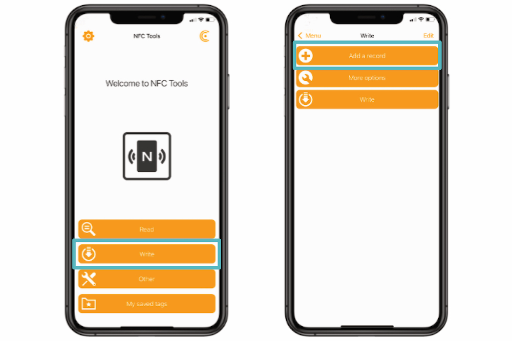
Select URL and enter the URL of the digital business card / website in the URL field. Then click OK.
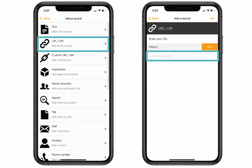
Go back to the home page of the app and click "Write". At the end, select "Save". A "Ready to scan" pop-up window will appear.
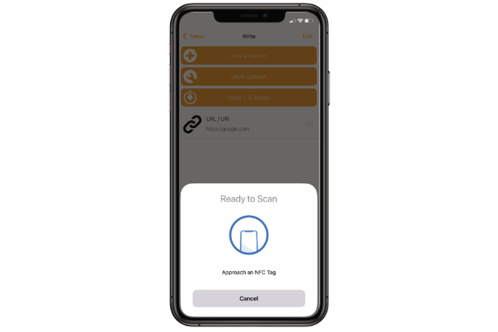
Put NFC on the back of your phone. If the tag is written, a confirmation pop-up appears on the screen.
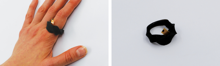
NFC RING
NFC Range: NFC technology typically has a limited range of a few centimeters. The standard range for NFC chips is approximately 4 cm or less. This means that the reader device must be relatively close to the chip for effective communication.
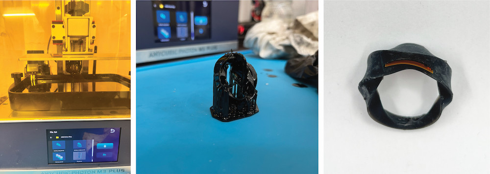
- I was wondering what the range of my chip was. I've tried reading it through various materials. I've covered it with plexiglass, fabrics, for example. Despite the plastic reading the chip worked well, so I decided to create my NFC 3D printed ring. I used the parametric design from the 7th COMPUTATIONAL COUTURE week. I just modified the ring and added a small pocket to insert the NFC chip.
TOOLS
- Micro NFC/RFID Transponder - NTAG203 13.56MHz
-
Rhino 7 & Grasshopper - Parametric Modeling |
- Anycubic Photon 3D Slicer Software
- Anycubic Photon M3 Plus - resin 3D printing.
- I 3D printed the ring using SLA (stereolithography) technology. You can follow The same process here: 3D PRINTING WITH RESIN
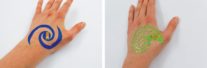
NFC TEMPORARY TATTOO
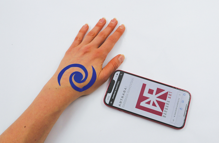
What would it be like to come to a party with only a tattoo on your skin instead of a purse with a credit card in it? The NFC chip is easily readable through the stickers. I give this example as a concept of a temporary tattoo that can be set up as you choose. Whether you want to share your business card or make a contactless payment. Design possibilities have no limits, I chose geometric futuristic motifs which were then carved on a vinyl cutter.
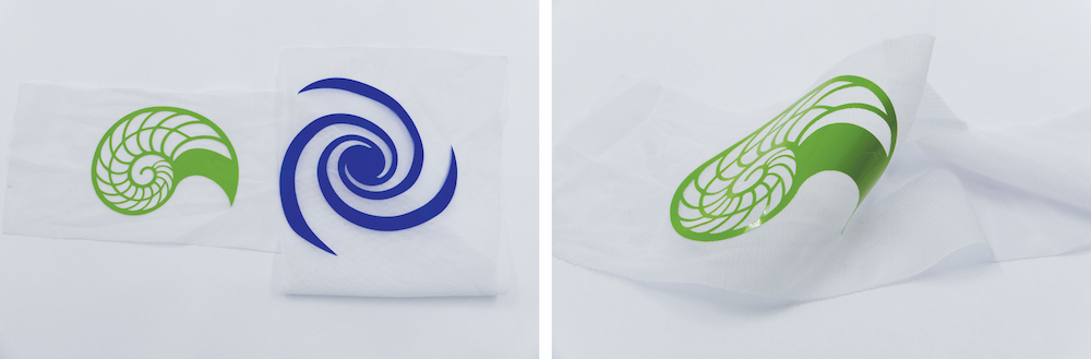
NFC | Applications in the context of fabrics
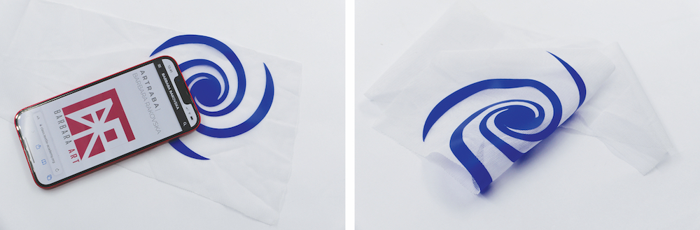
The small size of the NFC chip allows it to be placed on flexible materials. In the context of placing the chips in the fabric, I also found a few options that are waterproof (this would be advantageous in terms of washing). I created an example of how NFC patterns could work. The patterns were also cut on a vinyl cutter.
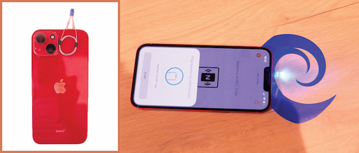
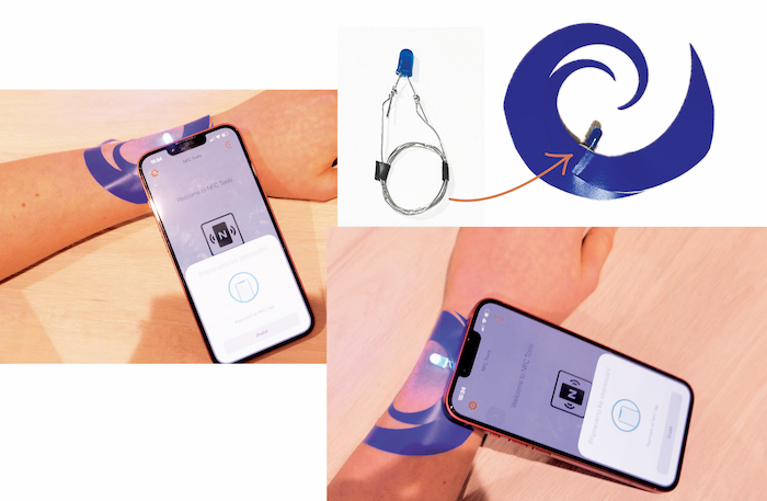
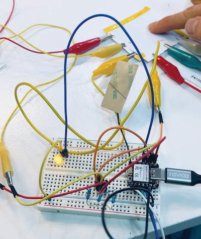
NFC LIGT | experiments
I found out that by using NFC reading technology, I can make the LED light up. This is a great way to show that it's working and also adds to its visual appeal. What I appreciate the most is that it doesn't need a battery or any other electrical source. I found tutorials on how to create a NFC detector for your phone and I subsequently applied this principle to the prototype.
Materials
-wire (any decent length) -tape -LED -NFC Enabled device -scissors
To make a coil, wrap a wire around your four fingers, leaving the first and last bit of the wire out. Tape the top part to make sure it doesn't fall apart. Bend the ends of the wire inward so it's easier to attach an LED. Finally, put the LED in the bent parts of the wire and your coil is complete!
References
- When my phone is trying to read a Tag the LED is blinking.