Digital bodies
This week’s topic is Digital Bodies, where we explore the human body as a concept, a medium, and a material that can be interpreted in different ways. The exploration will focus on appropriating one of these concepts and then materializing it through 3D scanning and laser cutting, along with other tools.
1. Objective
- Acquired knowledge on 3D scanning and modelling, mesh repair or manipulation.
- Executing from file to production workflow, from slicer to laser cutting
2. References, research & inspiration
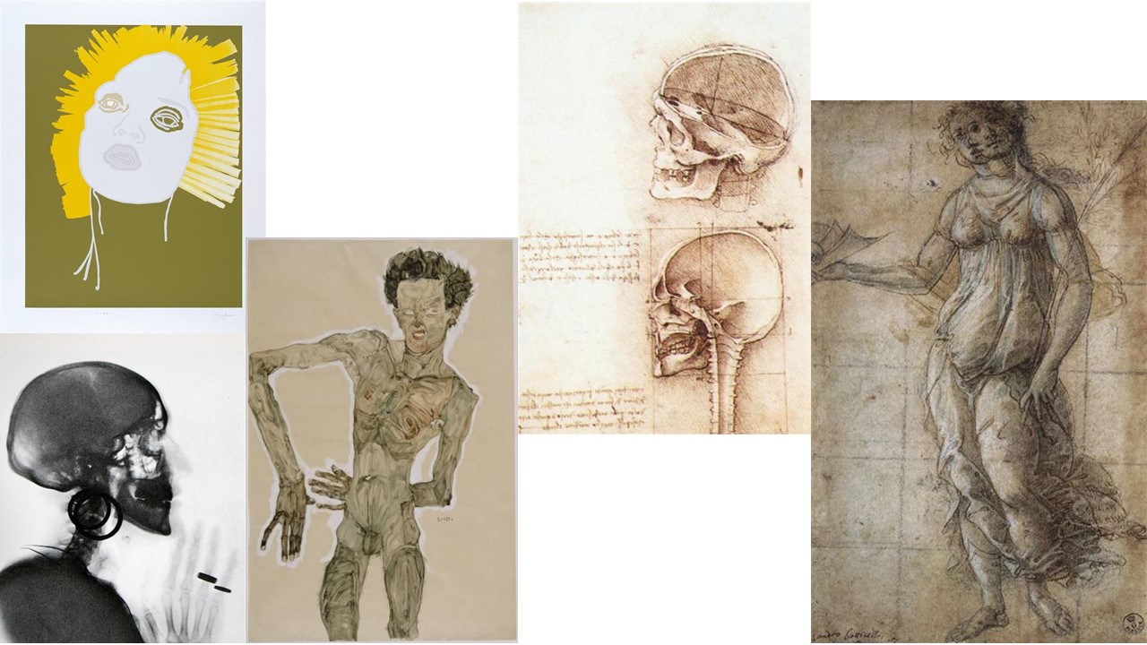
In terms of references related to the topic, well, I honestly remember seeing the human body explored in relation to fashion—first as a support, as a canvas, and as the foundation of clothing, but also clothing itself as an extension of the body.
When I was in the first years of art school, the perspective was somewhat different. It was more realistic and more focused on understanding anatomy: the relationship between the shapes of the skeleton and the muscles, and how movement was expressed through the body.
So, this is more like a general overview of some works that I feel communicate these concepts. They are somewhat more artistic, but at the same time, they are strongly connected to realism and the study of human anatomy.
For example, we have these works from Boticelli, Egon Schiele, Leonardo da Vinci, Gary Hume and Meret Oppenheim, and each one interprets the human body in a different way, emphasizing volume, movement, but also the internal structures of the body, with different degrees of expressiveness.
3. Tools
4. Process and workflow
3D Scanning
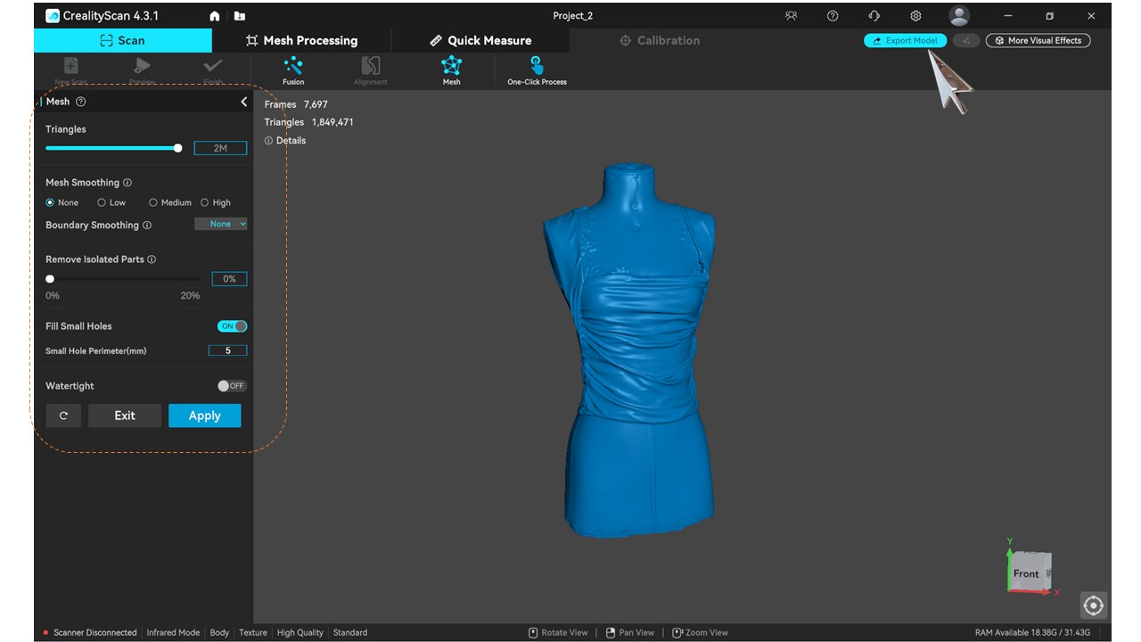
Moving on to the process, the first thing we experimented with was the use of a 3D scanner. We used a scanner from Creality, the Scan Raptor, which comes with software that allows you to see in real time how the point cloud detected by the scanner is being interpreted on the screen.
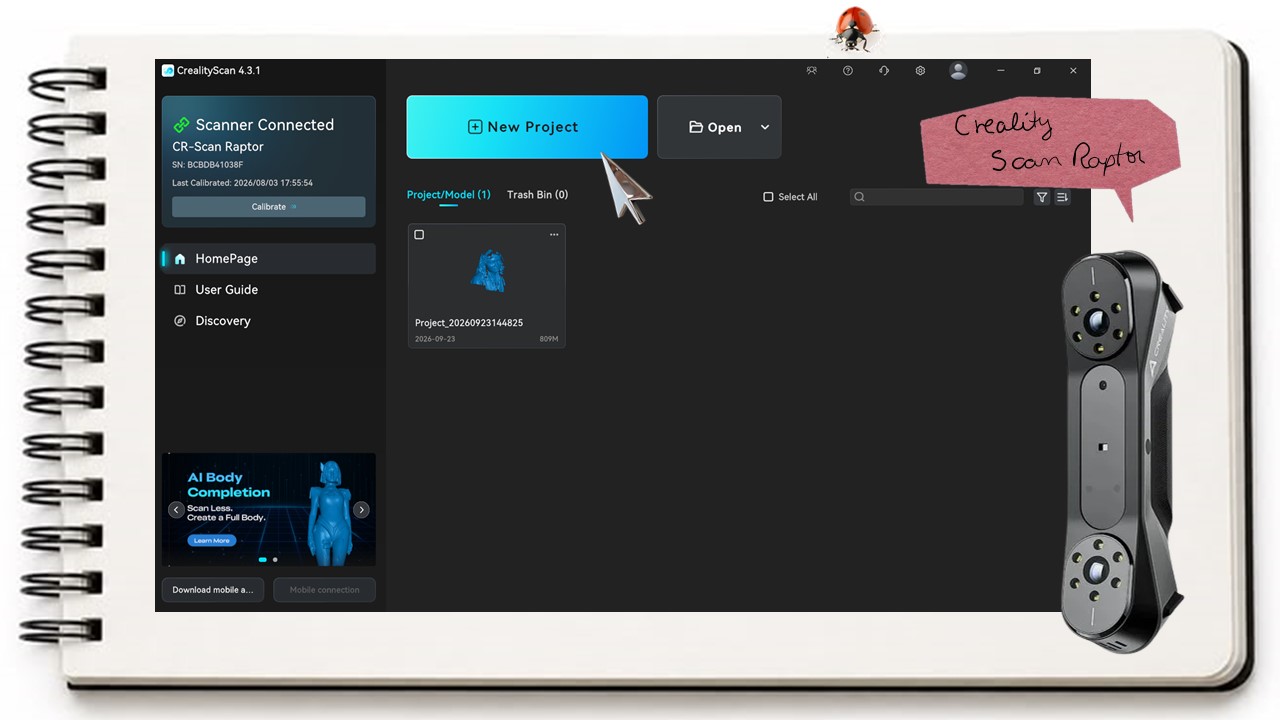
El escaner debe manipularse con cuidado, este tiene una correa que debe sujetarse a la mano. El escaner se conecta a la PC donde se abre el programa para usarlo, en este caso es un software de la misma marca que el scaner.
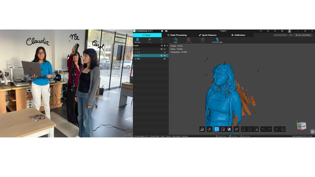
The first test was carried out with a real model, in this case, Carol. We tried to move the scanner as slowly as possible, from left to right, while going around the model. One thing to keep in mind is that you need to take your time and carry out the process slowly and in an organized way, because the scanner can lose the signal, especially if you are not using the reference markers that come with the scanner.
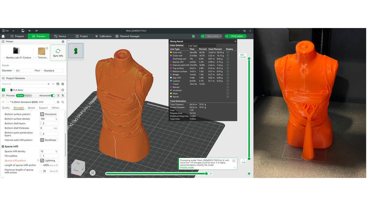
 The second attempt was carried out with a mannequin wearing a garment with several folds. Since the mannequin was completely still, it was much easier to capture, and we did not lose the scanner's signal at any point. Throughout the process, we always had to make sure that the scanner was kept at the right distance—not too close and not too far away.
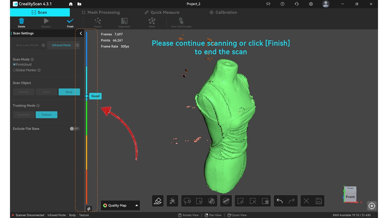 After that, we proceeded to process the point cloud. We removed some of the areas that had been captured, and finally, we obtained the model as an STL file, which we exported and then prepared for 3D printing.
Personal exercise
Continuing with the exploration, this time starting from a conceptual perspective, I found it interesting to consider how the human body was perceived based on the principles of the Andean worldview.
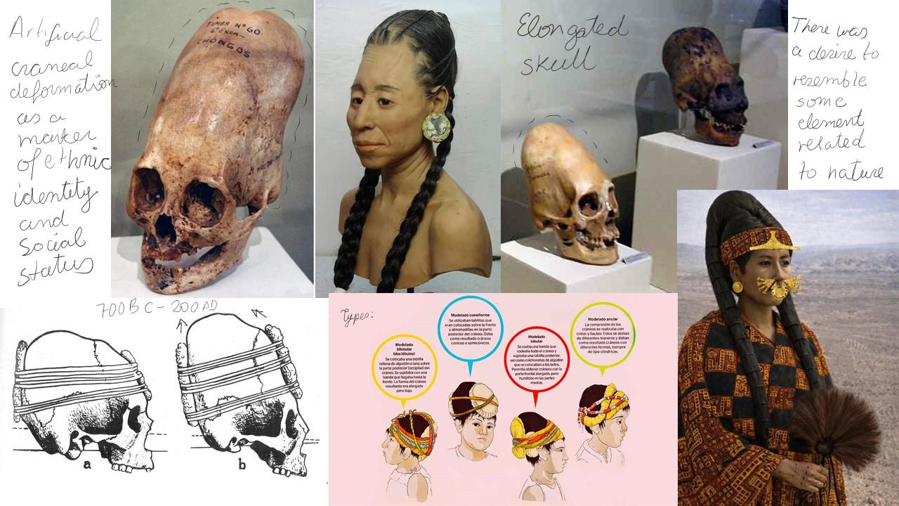 For the pre-Hispanic Andean mindset, the human body was not simply biological matter. It was more like a sacred canvas and a channel of communication with the cosmos. In other words, it was not merely something functional or earthly; it had a connection that went far beyond that.
Those of us who believe in this worldview understand that ancient Andean populations had a very deep relationship with their territory and with all the ecological events that took place within it. This is why there was such a strong interest in belonging to these places, but not simply in a physical sense—it was more about being in communion with them. There were also many entities that were considered sacred.
So, in the desire to establish a direct spiritual connection with these deities, a practice known as cranial elongation was carried out. When children were very young, their skulls were gradually shaped using boards or other forms of pressure that helped mold the head.
Having a stylized and elongated head was understood as a physical manifestation that recalled certain deities—for example, the apus, or sacred mountains. In this way, those who had elongated heads could demonstrate to their community that they belonged to an elite, since they shared this physical characteristic with nature itself. At the same time, this reinforced their connection between the earthly world and the celestial world.
Why was this done specifically to the head? I think this is an interesting question to consider, because the head and the face are an important part of a person's identity. Moreover, according to this worldview, the head was perceived as an axis of vital force, a place where different fluids and energetic forces passed through. It was also considered the center of thought and the reception of cosmic energy.
Therefore, modifying the structure of the skull was understood as a way of shaping the spirit itself, preparing it for the cognitive or ritual capacities that were required.
Create the digital body
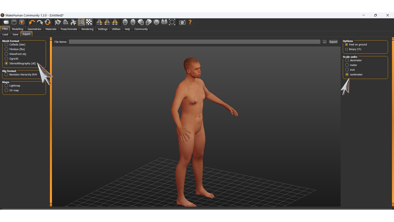
Building on these conceptual ideas, I found it interesting to use the software MakeHuman, where you already have a human figure that can be customized by changing different parameters, such as height, weight, musculature, age, and body proportions.
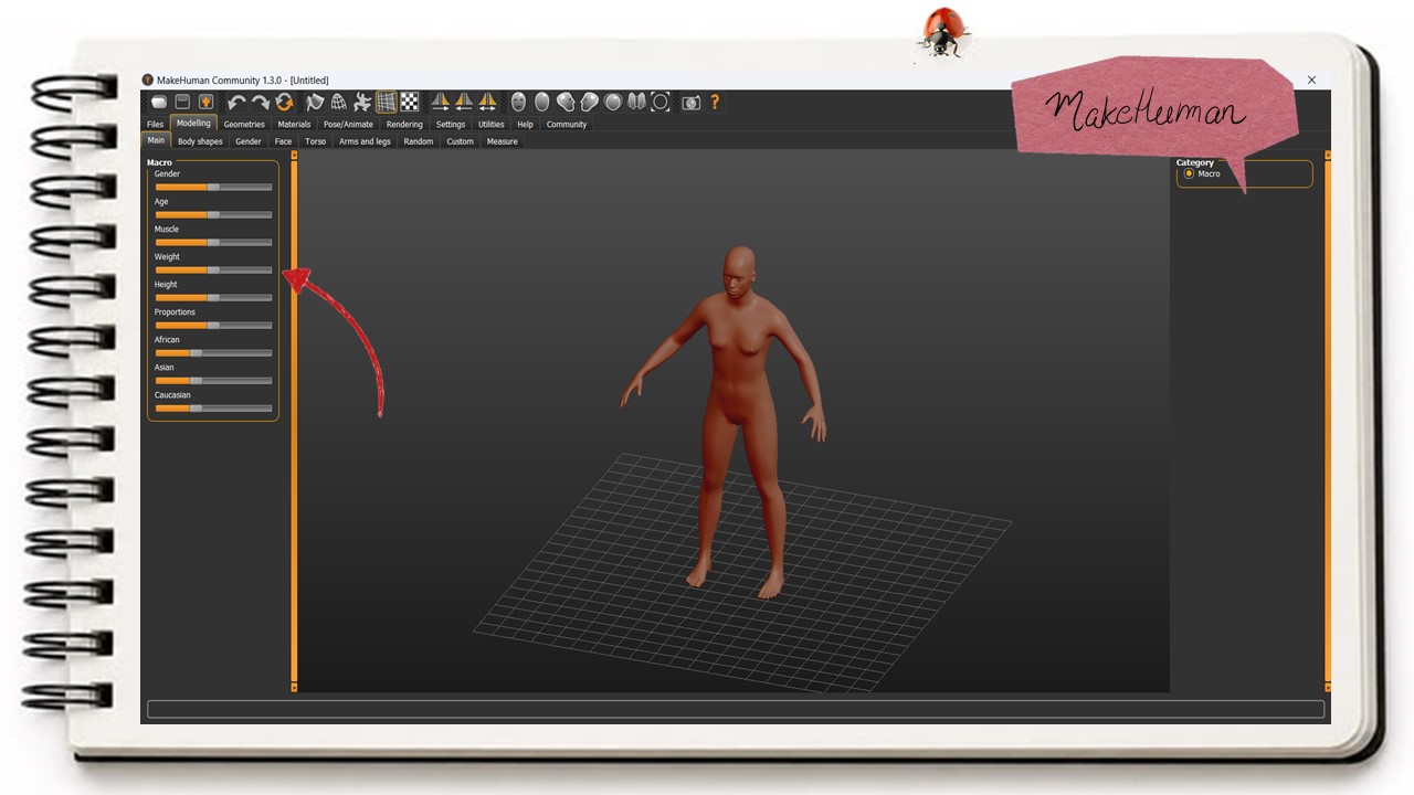
So, trying to approximate what the ancient inhabitants may have looked like, I created a human prototype that incorporated these characteristics. I then exported the model as an STL file.
Modify and edit
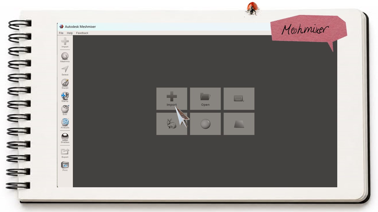
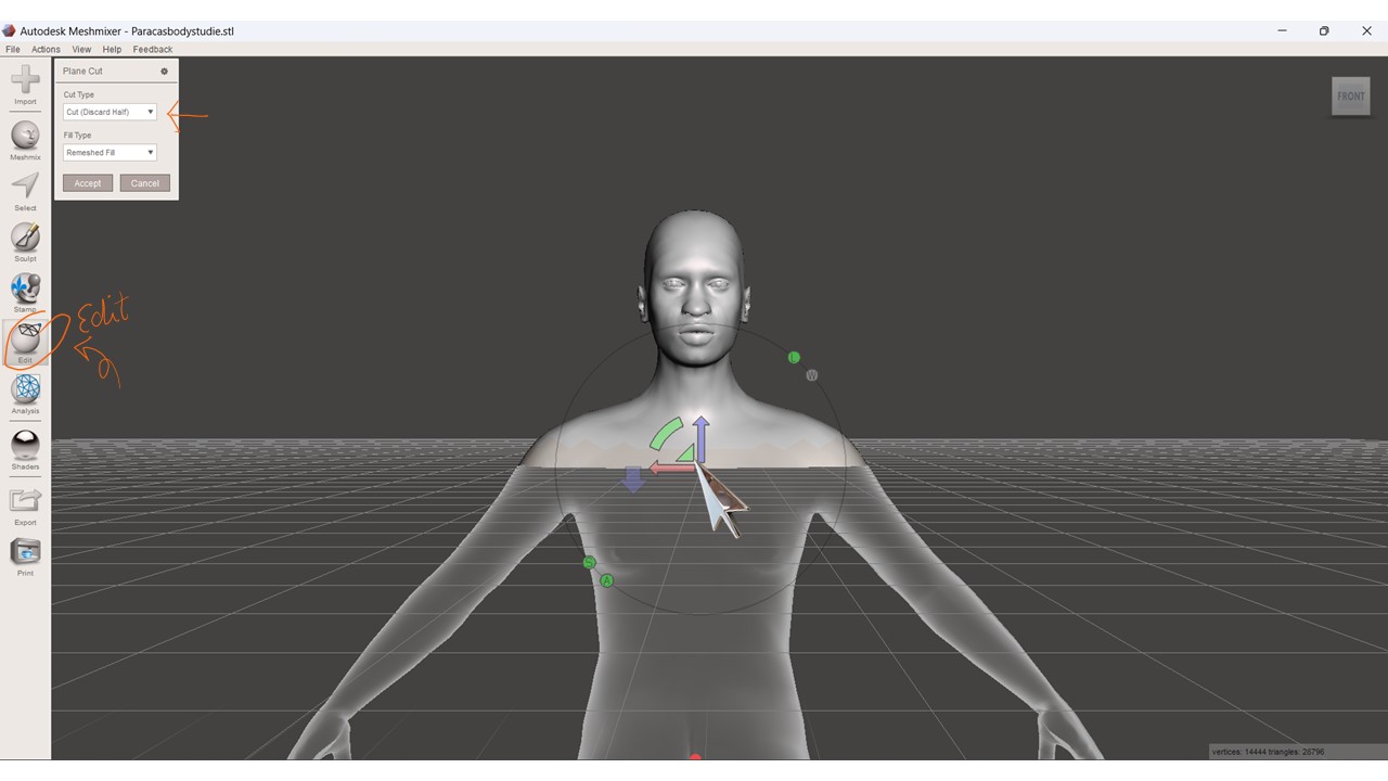
After that, I imported it into Meshmixer. Using the Edit tool, I created a cutting plane so that I was left only with the upper part of the body, from the neck up to the head. The head was the area that I was going to deform, so to speak.
Meshmixer has an option called Sculpt, which allows you to create organic deformations, almost as if you were sculpting clay. I used this tool to create an elongated volume around the head, trying to imitate the cranial deformation practiced by the people of the Paracas culture.
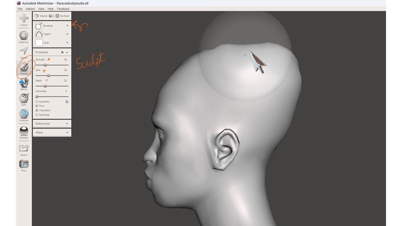
I mainly used the brush that adds volume, along with another brush that flattens certain areas. By combining both, I was able to shape the deformation and eventually obtained a fairly interesting result of what the skull of these people might have looked like.
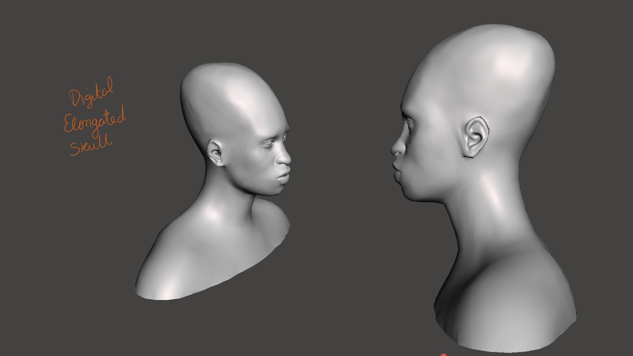
Surface variant
Continuing with the modification, I also wanted to relate the model to this whole idea of cosmic energy and spiritual forces. I wanted to give it a somewhat organic pattern, so the first thing I did was increase the number of triangles that made up the mesh: with CTRL + A > EDIT > REDUCE
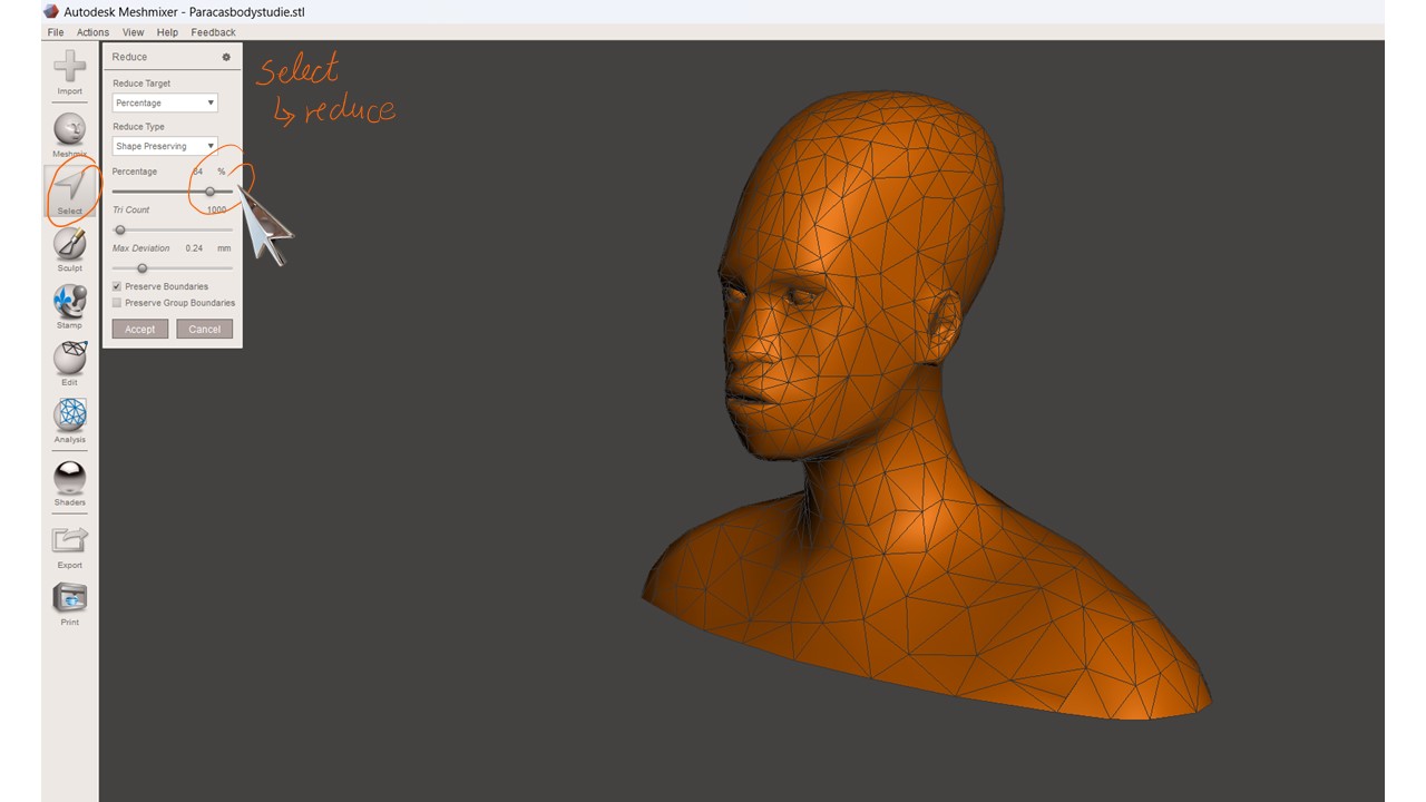
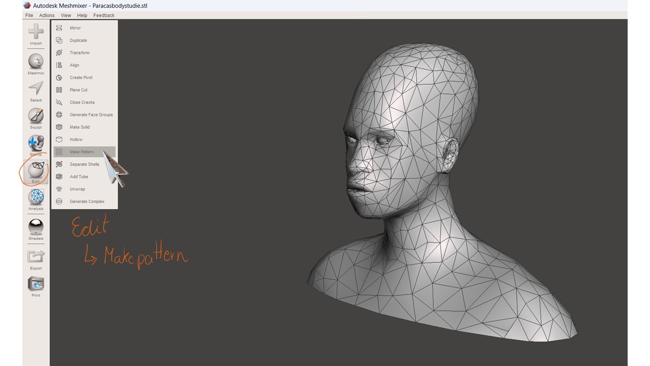
This allowed me to later apply a pattern, which in this case was the Dual Edges option. Using this pattern, which can be found under the Edit tool, I was able to create a kind of voronoid effect on the surface.
 Although there was an internal structure around the eyes and mouth, I tried to remove it, but it was not really possible because it was very connected to the outer structure. So, in the end, I decided to keep it. The effect did not look bad; in fact, it created something that resembled an X-ray, almost revealing the internal structure of the face.
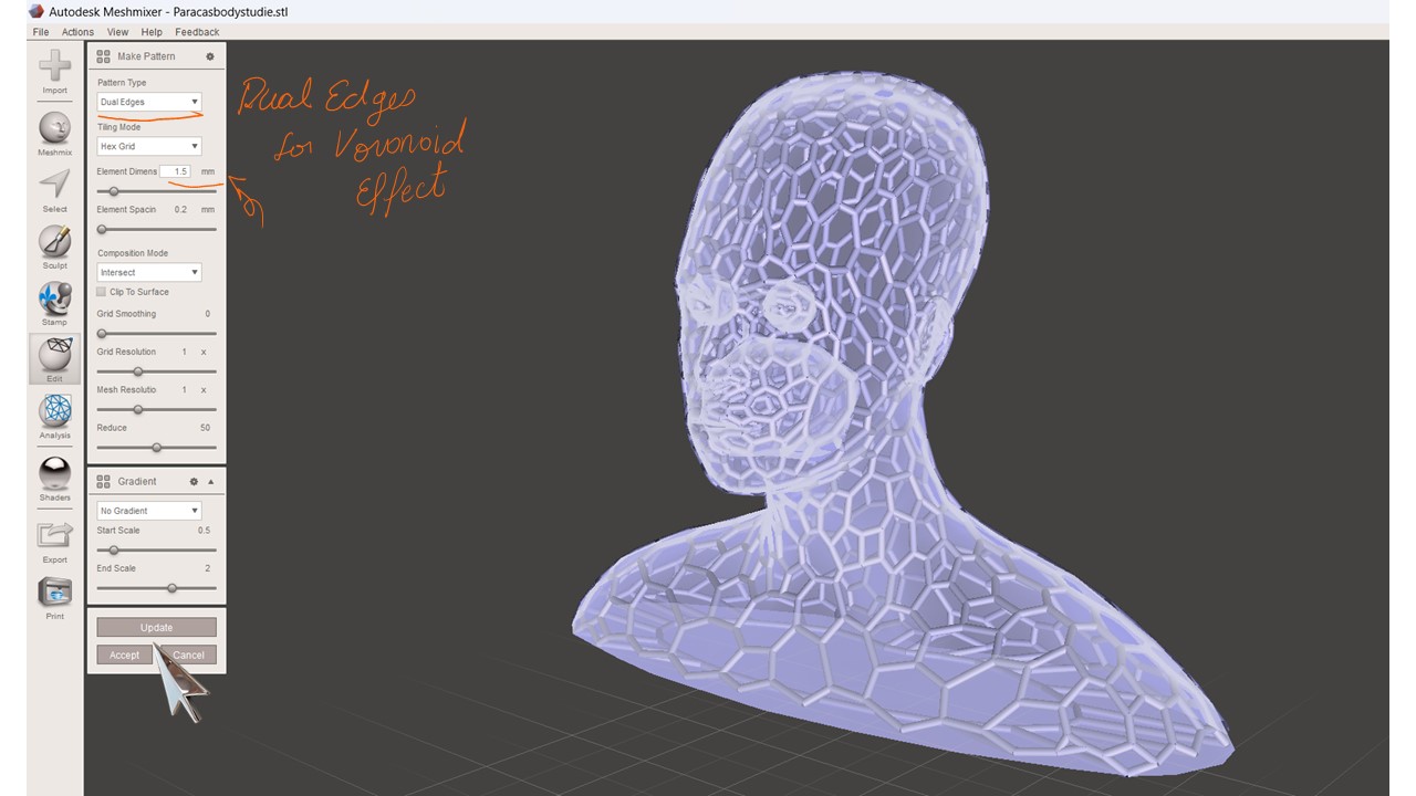
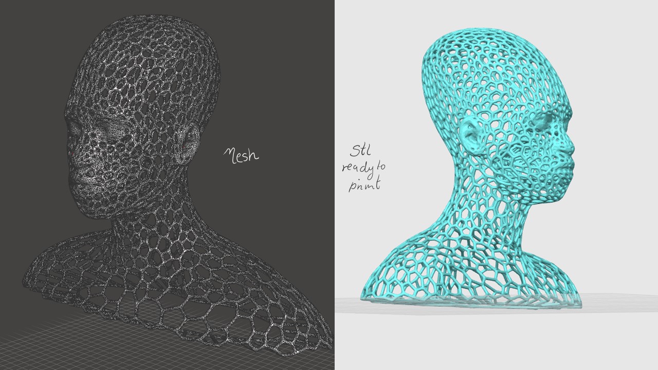
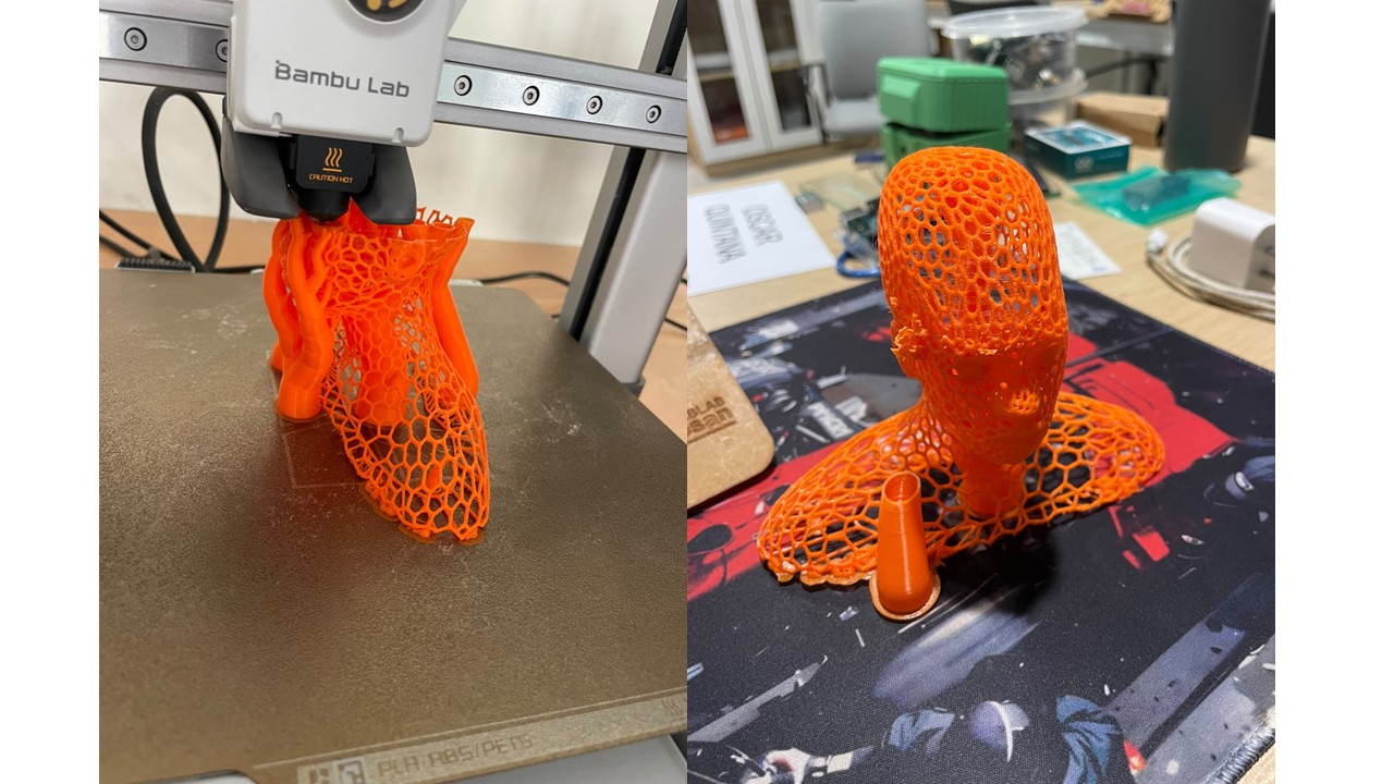
So, I ended up with this mesh, which was exported as an STL file and then materialized through 3D printing.
Prepare the files
With the first STL file I obtained from the elongated head, I opened it in the Slicer for Fusion 360 software, which I used to generate the 2D patterns.
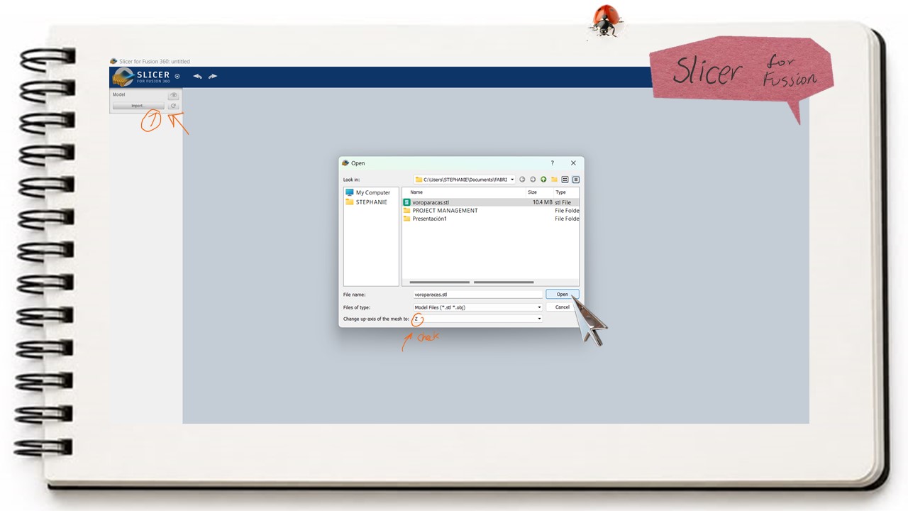 One important thing to consider here is the axis along which the model is going to be unfolded, since this determines the correct orientation. So I change it for Z axis and also check te measure of the object.
We also need to define the manufacturing parameters. In this case, for the material, we specified the units, length, width, and, most importantly, the thickness of the material we were going to work with.
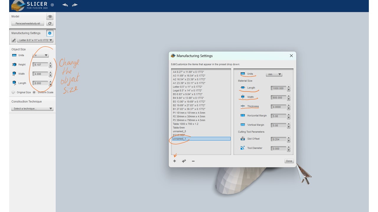
The software offers several construction options, each producing a different type of result. These results are also related to the overall size of the model, so the number of pieces generated will vary depending on the dimensions of the model being used.
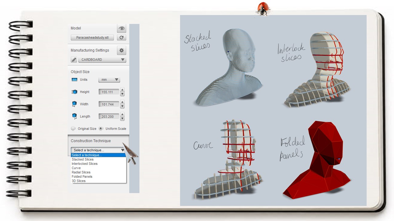
For this exercise, I chose the Radial Slices option because I felt that it allowed the construction of the head to be observed more clearly.
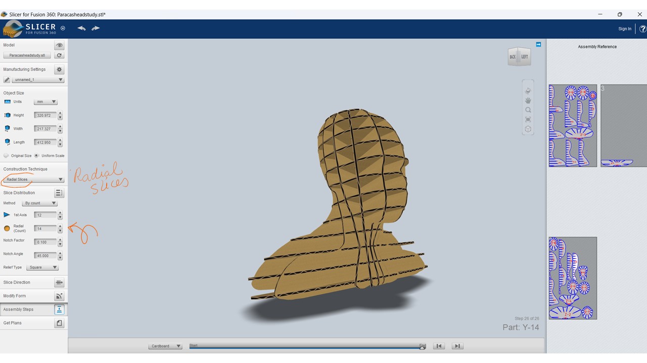
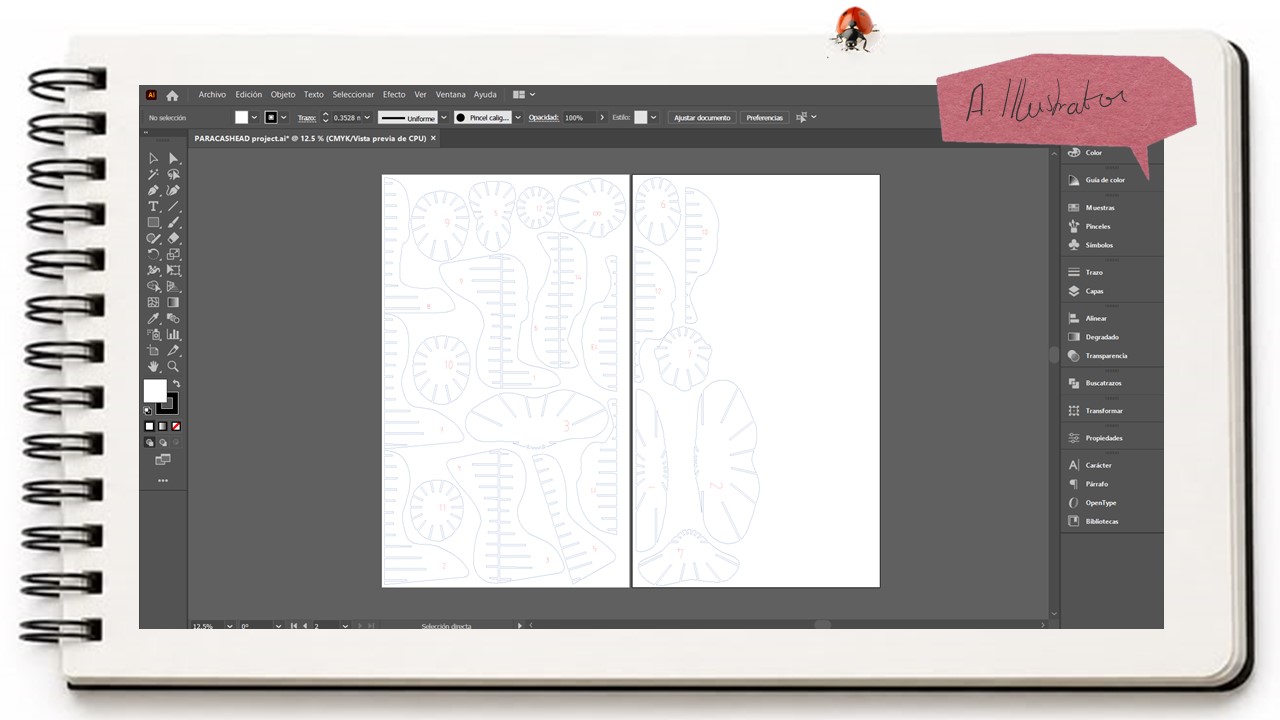
Finally, once the view and the cutting pieces were generated, they could be exported as DXF or PDF files. I chose to export them as a PDF and open the file in Illustrator, where I made some modifications. These mainly involved adjusting certain pieces that seemed to have very narrow margins, as well as editing the reference numbers that would indicate which pieces needed to be joined together.
Materialization
Moving on to the materialization stage at the Fab Lab ESAN, there are two laser cutting machines from Trotec. These machines have a cooling system and a ventilation duct, which make the operation safer by preventing the workspace from becoming filled with smoke.
It is important to understand how the machines work, as well as to use the appropriate personal protective equipment, especially safety glasses when monitoring the process.
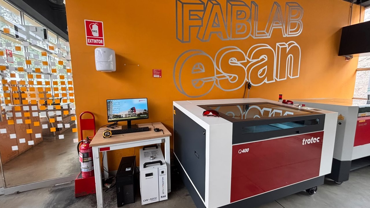
The software used with these machines is called Trotec Ruby. This is where the file is imported and we specify which lines are going to be cut and which ones are going to be engraved.
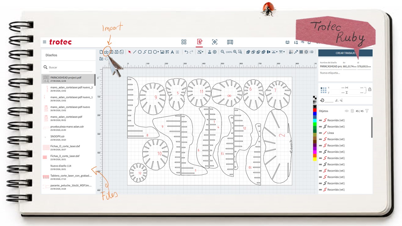
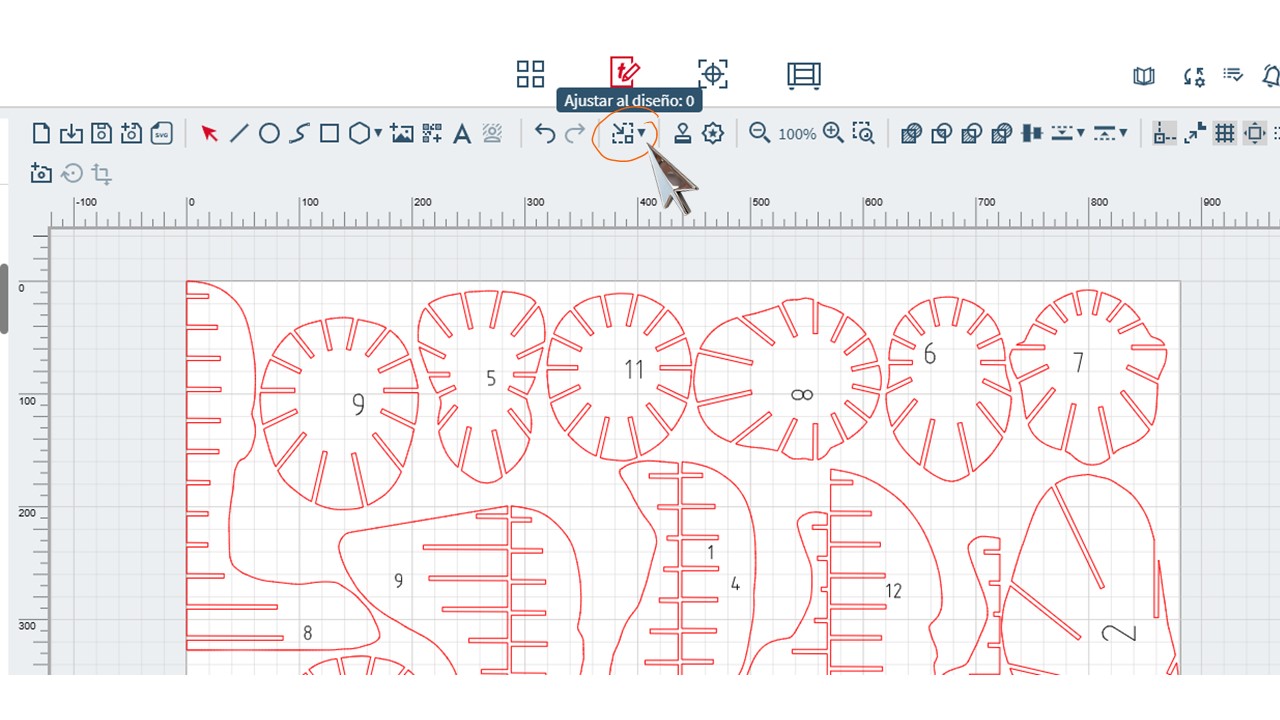
Once these settings have been defined, the design is adjusted so that the pieces are positioned as accurately and efficiently as possible within the material area. Finally, we go to the option called Create Job, where we can see the cutting parameters.
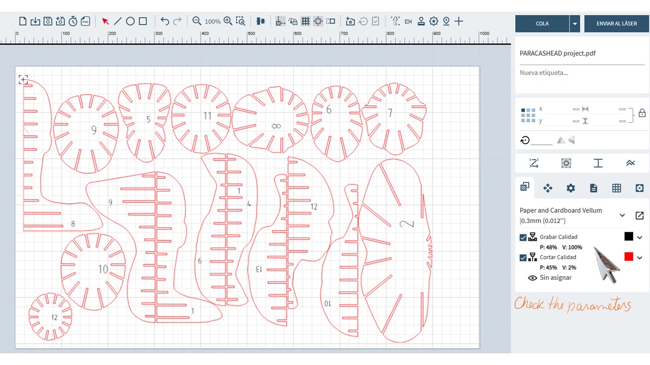
These parameters are directly related to the type of material, so it is very important to check them and, whenever possible, carry out some tests, especially if the laser cutter does not have predefined settings for that material.
In this case, there was already a predefined profile for 3 mm cardboard, with specific cutting and engraving parameters.
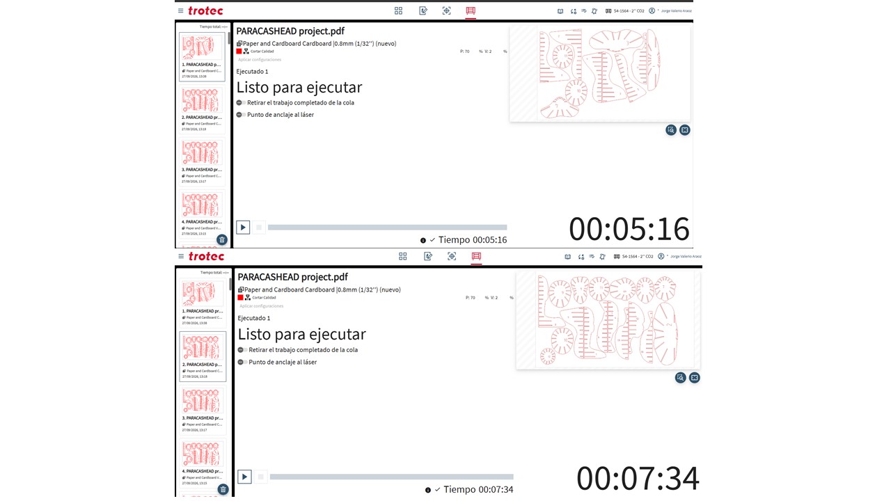
Finally, the job is sent to the machine, where we can see the estimated total processing time for each file.
Before sending the job to be cut, it is necessary to calibrate the distance between the laser head and the material. This is done using this small device, which allows us to raise or lower the material sheet. This way, we make sure that the laser is neither too high nor too low, so that the parameters we selected previously can work properly.
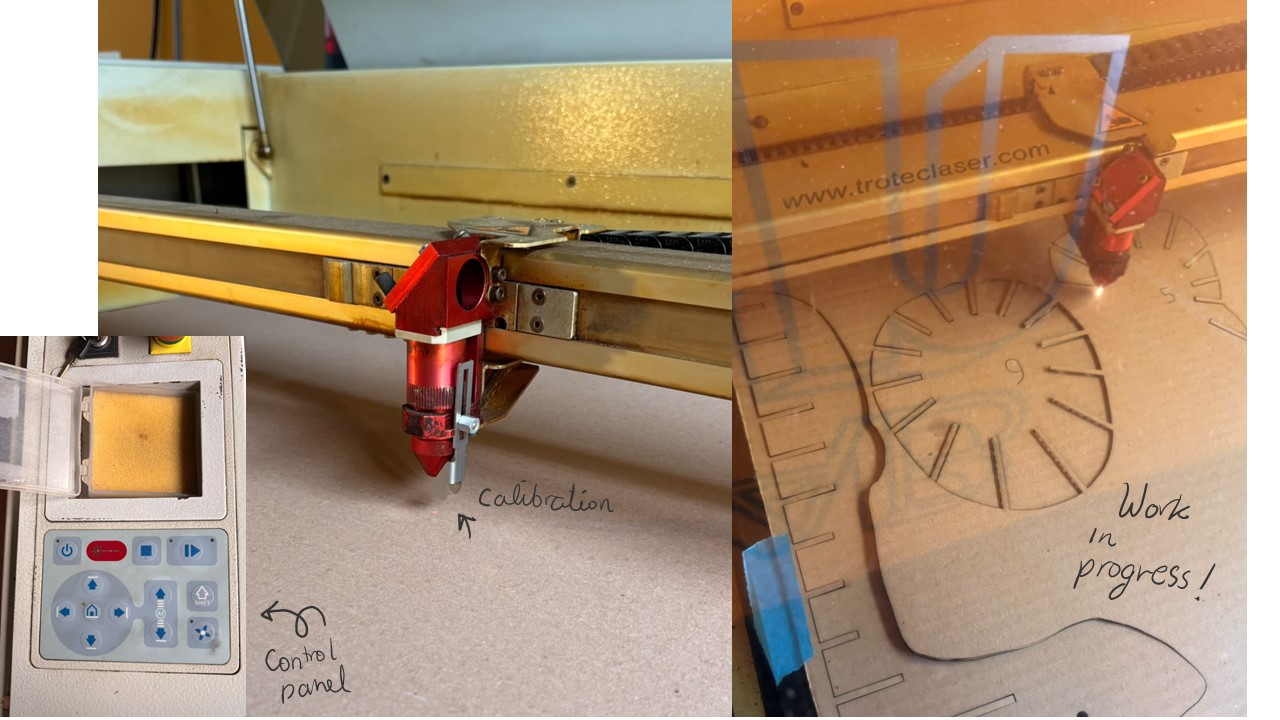
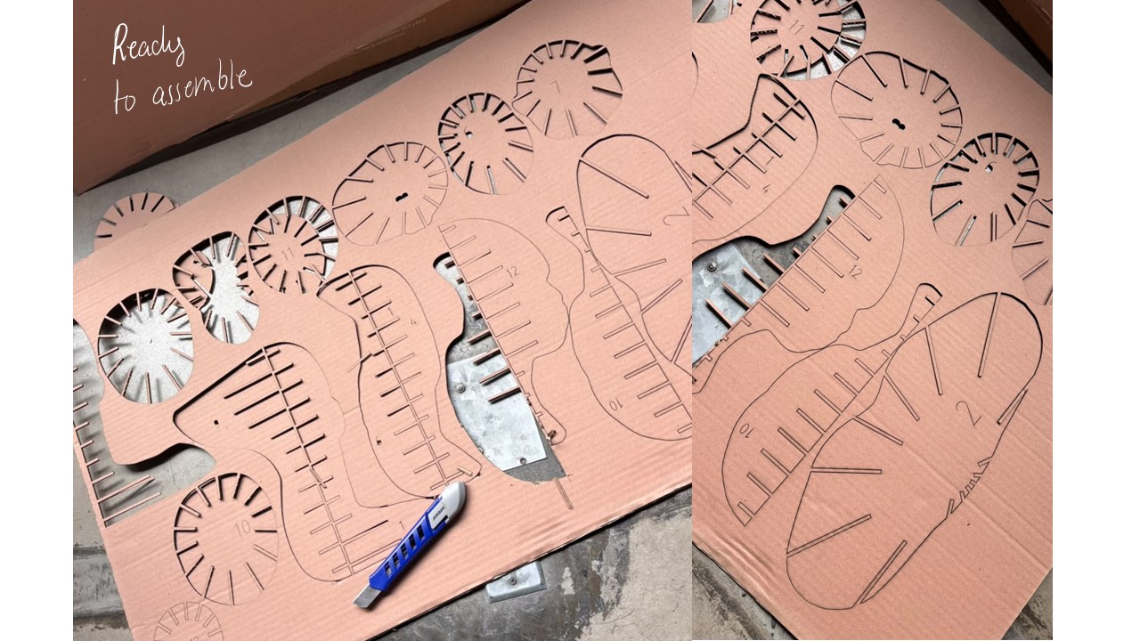 Finally, the cutting process is carried out, and we obtain all the pieces ready for the corresponding assembly.
5. Results
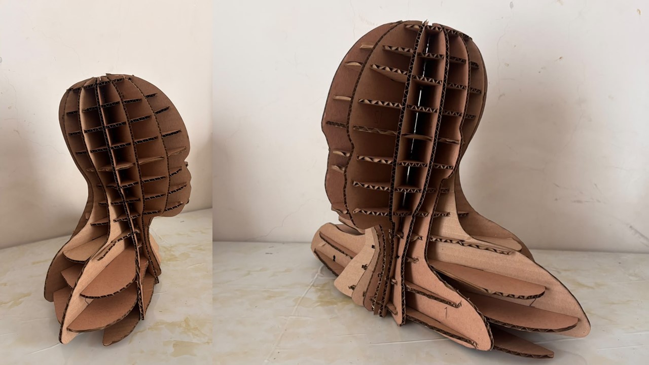
The pieces I obtained were 12 horizontal pieces and 13 vertical pieces, which were interconnected radially to create the final figure.
I do feel that I could have elongated the head a little more so that the elongated skull effect would have been more noticeable, but I think the concept worked well.
Assembly process steps
3D Model
Representation wth AI
Since we had also been exploring generative image tools, I used ChatGPT to give the figure a somewhat more translucent and golden appearance. I was thinking about the desert landscape of the territory where these people lived, and I wanted to use that visual language to provide some context for a possible complete human figure based on these construction patterns.
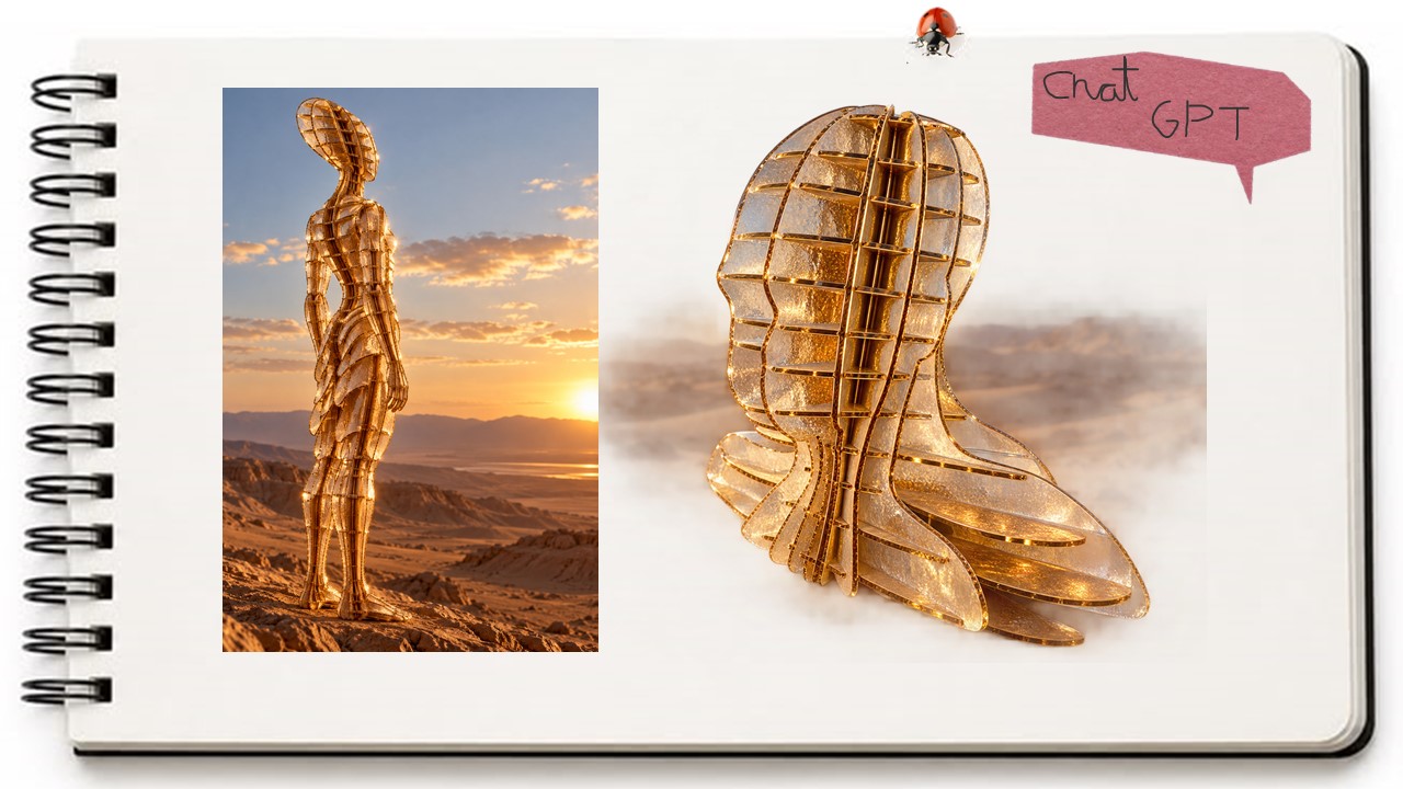
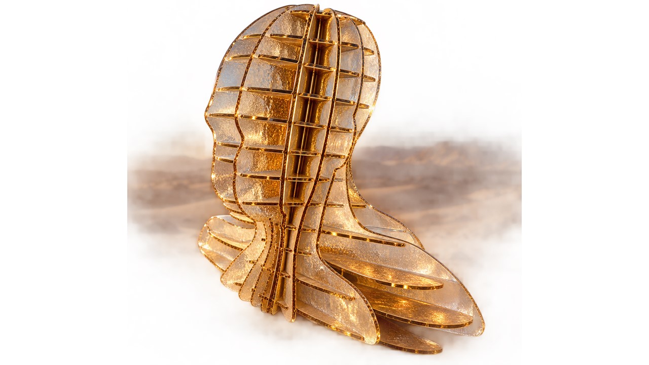 The result was very interesting. It conveyed this deep connection with the spiritual territory, and also explored how the presence of a person could be understood in relation to the territory and these more celestial entities. In a way, it represented the relationship between the earthly world and the celestial world.
To complement the exercise, I took this figure into an AI-based 3D modeling tool, in this case Tripo, which generated this 3D model for me.
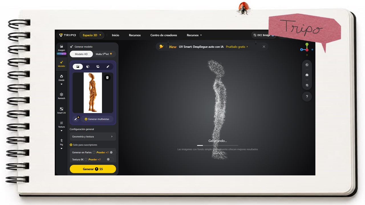
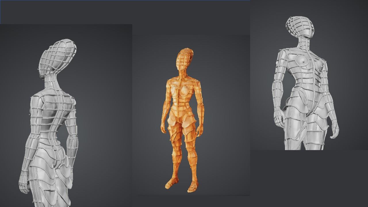
6. Weekly reflection & critical thinking
What I learned from this process was how we can take physical matter into the digital realm, edit and modify it, and then bring it back into the physical, material world. I find this iteration between the physical and digital realms very interesting, especially because there are so many different tools we can use, each giving us very varied and expressive results depending on how we approach them.
It would have been interesting, perhaps during the scanning stage, to scan myself, if that had been possible, and create some kind of bodily deformation that I could relate to a particular territory or deity that I personally feel connected to.
It also would have been good to experiment with other types of materials. Although I have worked with laser cutting before and I am familiar with its potential, applying it to this particular exercise was a very good opportunity to revisit the technique and gain a different perspective on what we can actually do with it.
I would also consider, whenever possible, using materials that do not cause unnecessary environmental harm or simply become waste after the process. In my case, I tend to keep many of the things I make. I actually have work that I have kept since childhood, because for me, everything we create comes with a responsibility. It is a very significant responsibility—we are responsible for the things we bring into the world and materialize.
In that sense, I plan to keep this work as a reference and find ways to give it another use in the future. Even the leftover cardboard pieces could potentially be reprocessed. Since the cutting process was done with as little waste as possible, these remaining pieces could perhaps be transformed into a new material that we could use for another cutting process.
So, for me, this process is not only about moving between the physical and digital worlds, but also about thinking about what happens to the material once the process is finished, and what other possibilities we can create from what remains.
7. Fabrication files & References
File: Laser sheets paracas head File: 3d modelling paracas head File: 3d modelling paracas head voronoid