Week 8 – Soft Robotics
Assignment
Design and fabricate a soft robotic system using flexible materials and pneumatic actuation.
Initial Design and First Trials
A first soft robotic design was planned.
Initial mold-making results were not successful, so this design was abandoned.
Reference Research and Model Selection
After reviewing previous Fabricademy works shared by Fabricademy 2024 alumna Aslı Aydı Aksan, a mold model originally created by Samson, a Fab Academy 2023 student, was selected.
To strengthen the research context beyond student references, I also reviewed external soft robotics precedents, especially pneumatic systems and flexible silicone actuators developed in research and bio-inspired robotics.
External references
- Harvard Soft Robotics Toolkit — open resources on pneumatic soft actuators and fabrication methods
- Festo Bionic Projects / Bionic Cobotics — examples of soft, bio-inspired actuation systems
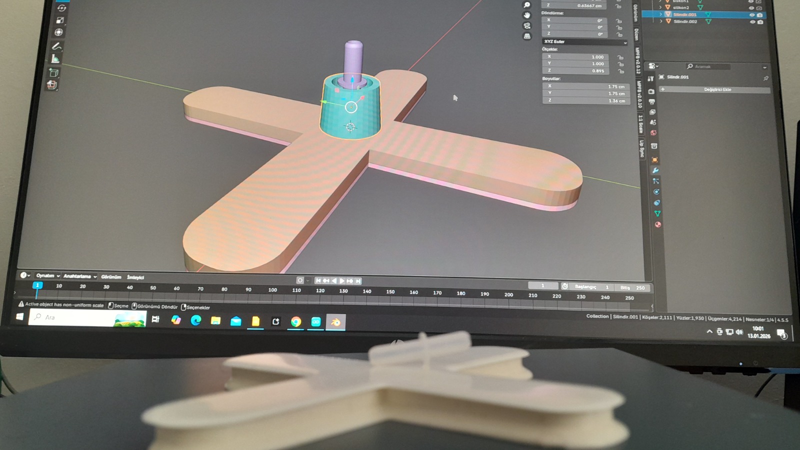
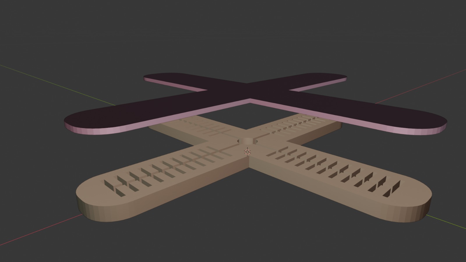
3D Modeling – Blender
The model was imported into Blender.
Without changing the main structure, a closure system and air inlet were designed.
Boolean operations were used to simulate silicone-filled areas between mold parts.
The final design was exported as an STL file.
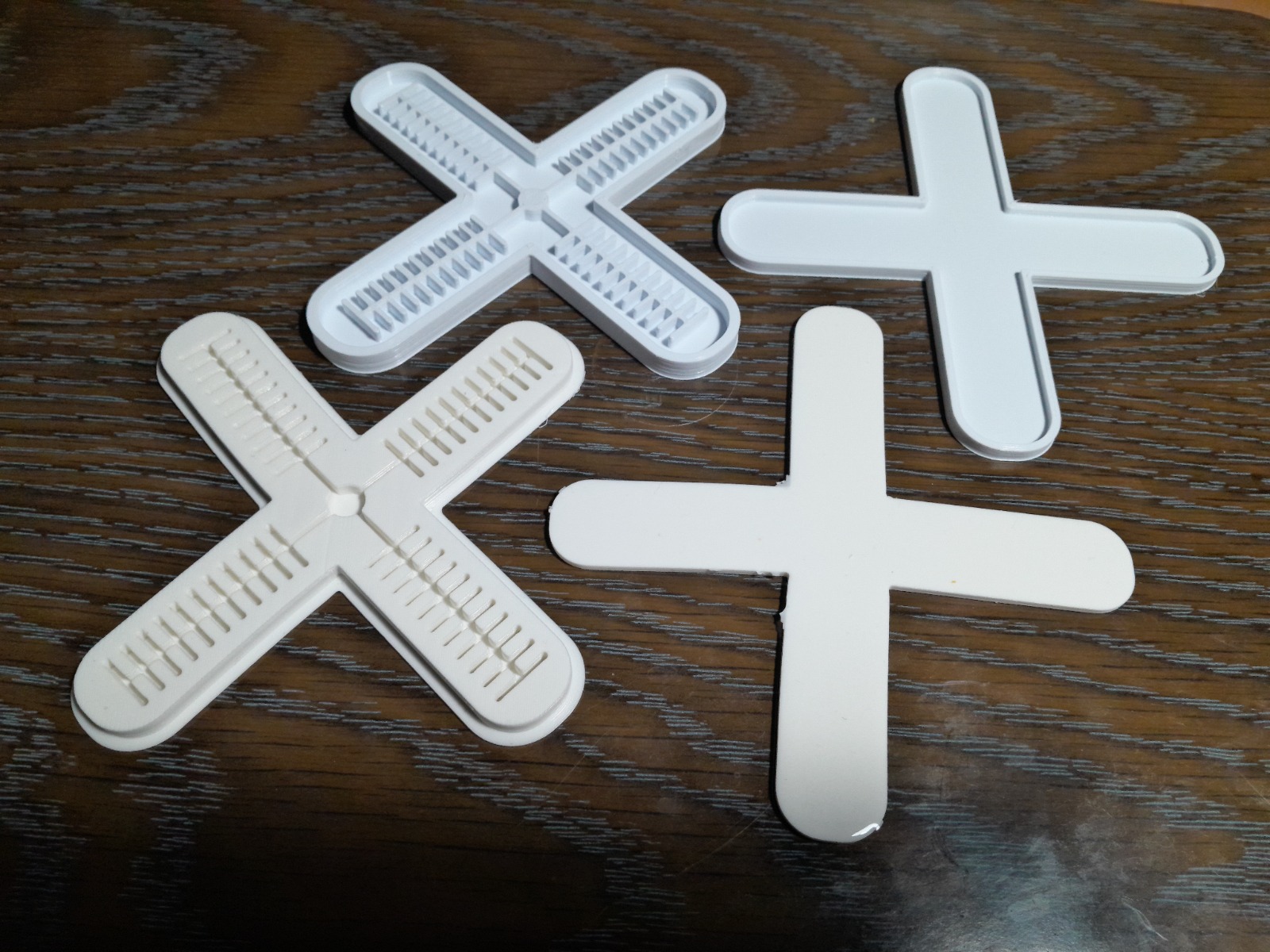
Mold Fabrication – 3D Printing
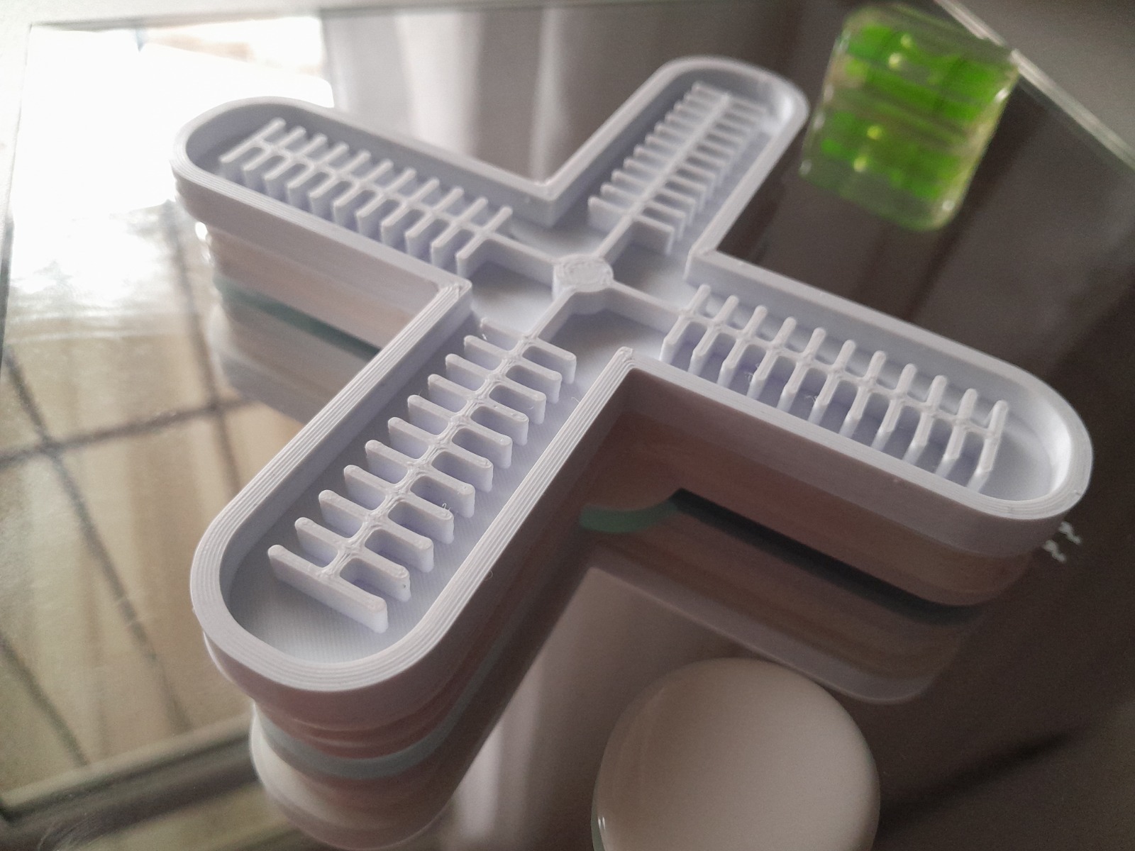
The mold was prepared for 3D printing on an Ultimaker printer.
Print settings
- Material: PLA
- Nozzle temperature: 200 °C
- Bed temperature: 60 °C
High acceleration was avoided to preserve mold surface quality for silicone casting.
Silicone Material
The silicone used in this project is RTV-2 silicone.
It is a two-component flexible silicone suitable for soft robotic and pneumatic systems.
For soft robotic applications, materials with low shore hardness, such as Ecoflex 00-30 or similar alternatives, are generally recommended to allow higher flexibility and deformation.
Safety Data Sheet (SDS)
The safety data sheet for the silicone material used in this project can be accessed here:
[Insert SDS link or PDF here]
Silicone Casting Process
Even with small quantities, accurate ratio measurement was critical.
Key observations
- Silicone must reach small details
- Air bubbles should be removed with a pin
- Casting surface must be completely level
- Full curing time must be respected
- Sharp tools are required for trimming excess silicone
- Continuous cleaning during casting is essential
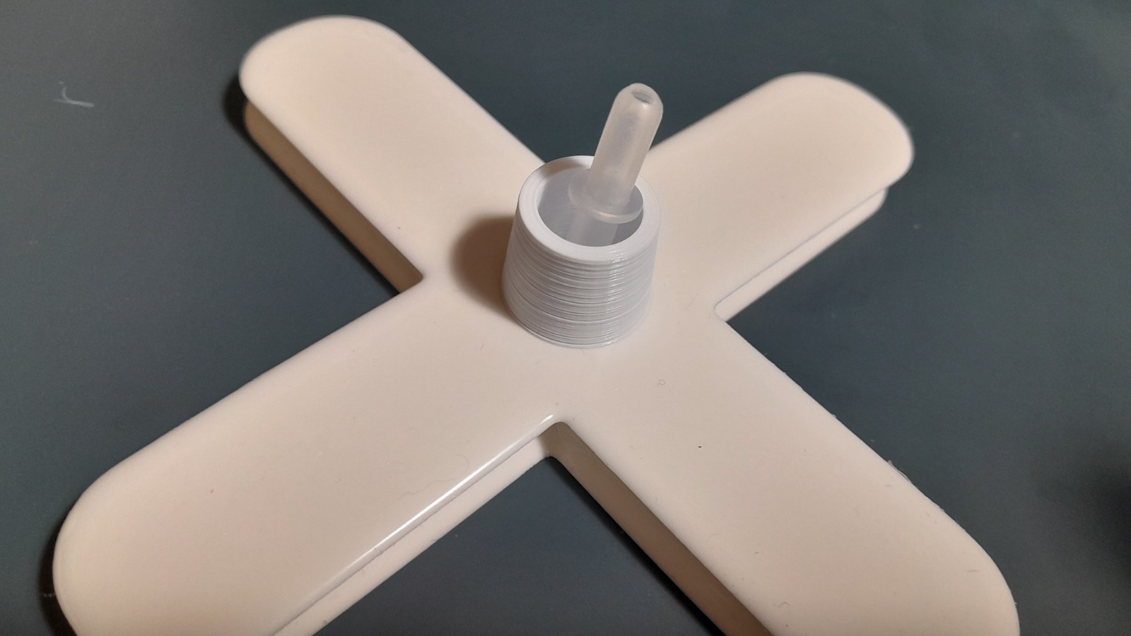
Assembly and Air Inlet Integration
After curing, the silicone parts were removed from the molds.
Two silicone parts were bonded together using freshly mixed silicone.
An additional small mold was used to reinforce the air inlet, ensuring a stronger pneumatic connection.
Equal silicone ratios were maintained to preserve uniform flexibility.
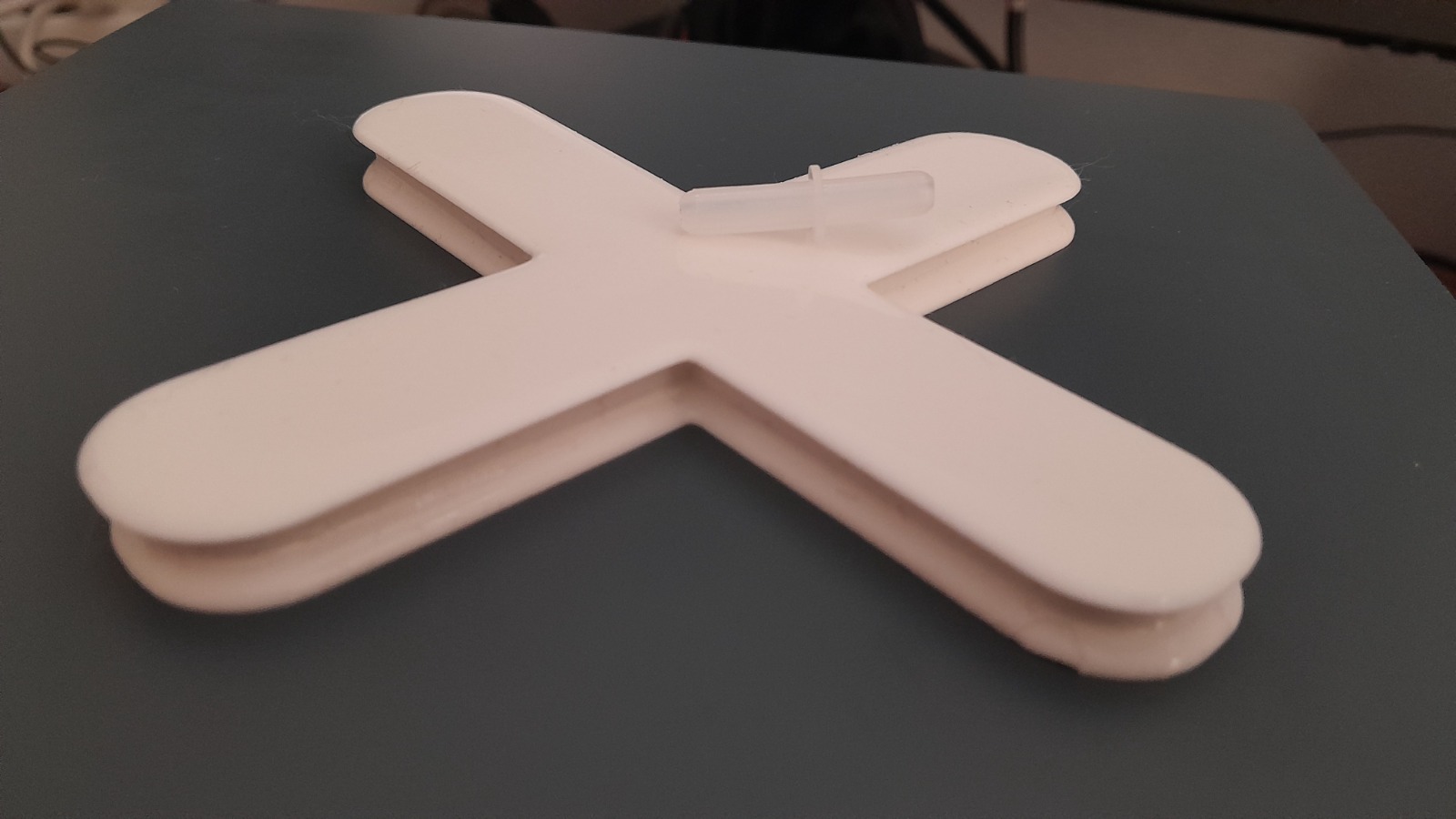
Final Soft Robotic Actuator

Initially, a wrist-wrapping soft robotic system actuated by a pear pump was planned.
Due to difficulties in achieving a sufficiently thin silicone structure, this concept was abandoned.
Instead, a previously tested soft robotic structure inspired by Fab Academy references was successfully fabricated.
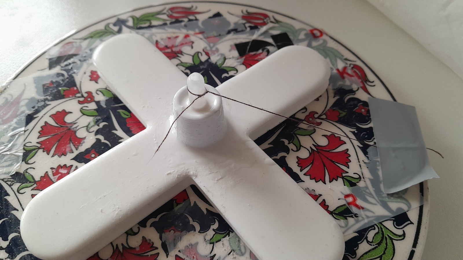
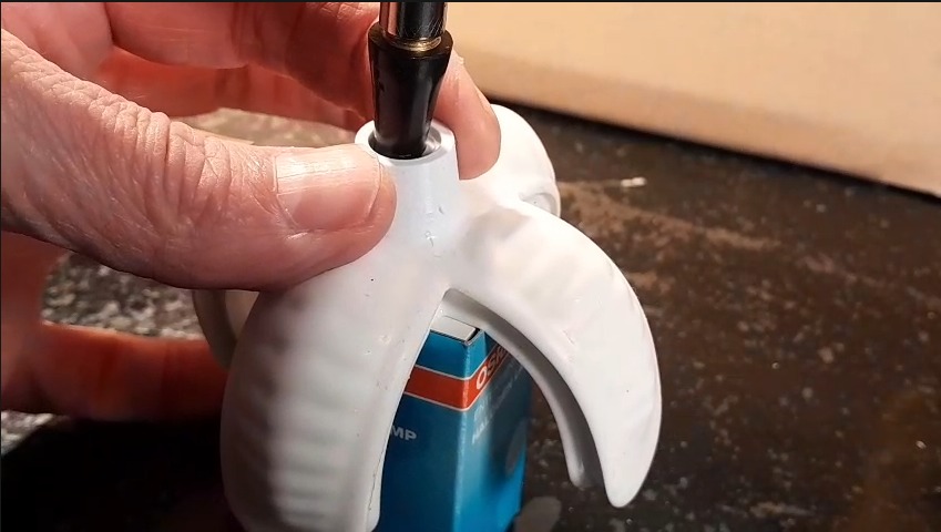
Inflation Process
The actuator was inflated using an external air source connected through a plastic tube.
Air pressure was introduced into the internal chamber, causing the thinner silicone wall to expand first.
Because the structure was designed with asymmetric wall thickness, this pressure difference generated bending motion.
This step was essential to test whether the actuator could successfully grip or curl under pneumatic activation.
Actuation Test
Step 1 — Initial inflation
The actuator began to inflate and showed the expected deformation pattern.
Step 2 — Pressure increase
As pressure increased, the pneumatic chamber expanded further, but structural weaknesses became more visible.
Step 3 — Failure analysis
The tests revealed two main issues:
- air leakage in the system
- weak adhesion between the plastic tube connector and the silicone body
In a later compressor-based test, the actuator inflated more strongly, but excessive pressure caused rupture at the weakest point.
Final Testing and Failure Analysis
During testing, several behaviors were observed:
- In the first inflation attempt, the actuator started to expand but did not continue because of air leakage
- Leakage increased as pressure rose, showing that the tube connector did not bond well to the silicone
- In a stronger test using a compressor, the actuator inflated successfully, but the silicone ruptured under excessive air pressure
These tests were still valuable because they clearly revealed the structural weaknesses of the system.
Structural Behavior Explanation
This actuator was designed with asymmetric wall thickness:
- Bottom layer: thick (structural support)
- Top layer: thin (designed to expand)
When air pressure enters the chamber, the thin side expands first.
This expansion bends the actuator toward the thicker side, creating a gripping / curling motion.
If both sides had equal thickness, this controlled bending behavior would not occur.
When inlet pressure and air release are properly regulated, the actuator’s gripping, opening, and releasing motion can be controlled more reliably.
Actuation Video
The video is stored directly in the GitLab documentation folder instead of an external platform.
Reflections and Learnings
- Silicone work requires patience, precision, and time
- Accurate ratio measurement is essential
- Mold surface quality directly affects silicone performance
- Boolean simulations in Blender are highly effective
- Air inlet design is a critical structural element
- Pressure control is as important as material choice
- Failure points provide valuable design feedback
Documentation Note
The process was originally documented in video form.
To make the documentation more sustainable and easier to maintain within GitLab, the key steps are also described here through images, written explanations, and a GitLab-hosted MP4 video.