10. Open Source Hardware - From Fibers to Fabric
Wool Picker Machine
A wool picker is a machine that separates and aligns raw wool fibers, making them suitable for further processing in the textile industry. It typically features a rotating drum with spikes to comb through the wool. A wool picker is a critical tool in the early stages of wool processing. After shearing, the machine's rotating drum with spikes combs through raw fleece, separating and aligning fibers while removing impurities. This automated process streamlines and cleans the wool, setting the stage for subsequent steps like carding and spinning in textile production. The wool picker significantly enhances efficiency, ensuring a consistent and high-quality output for the manufacturing of various woolen products.
Research & Ideation
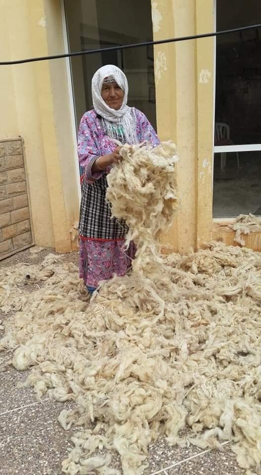
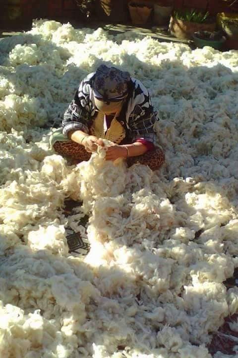
Our inspiration for developing a wool picker machine stemmed from the traditional practices observed in Jordan. Witnessing the meticulous and skillful techniques employed by these craftsmen in manually cleaning and picking wool from the raw fleece sparked an innovative idea within our team. Recognizing the labor-intensive nature of this process, we were motivated to streamline and modernize the method by creating a wool picker machine. This machine would automate the intricate task of separating and preparing wool fibers, drawing from the efficiency and precision of traditional practices while significantly reducing the time and effort required. In drawing inspiration from the rich heritage of wool craftsmanship in Jordan, we aim to blend tradition with technology, creating a tool that not only preserves cultural techniques but also enhances productivity in the textile industry.


The reference for these photos is Stages of Re-Mastering the Weaving Process
References & Inspiration
Honoring heritage and embracing technological progress.
Machine Anatomy
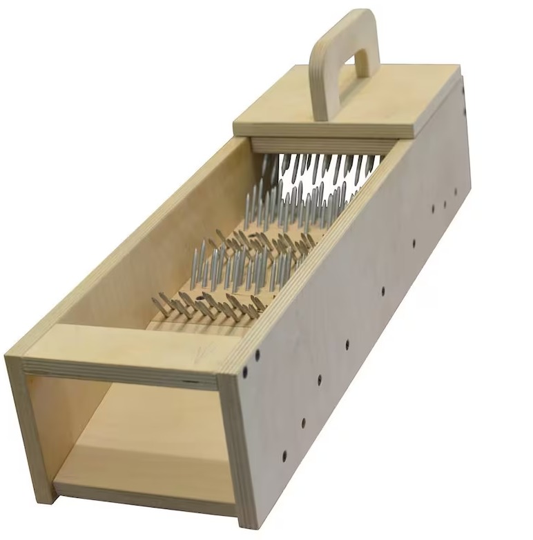
A DIY wool picker machine comprises a robust frame, and a picker drum with spikes for aligning wool fibers. A feeding mechanism introduces raw wool, while beaters or brushes aid in cleaning. The DIY nature allows for customization, making it an inventive solution for automating the labor-intensive process of wool preparation.
TOOLS AND SOFTWARE
- RHINO
- CURA
- JOB TROTEC
- ULTIMAKER S5-
-
Screwdriver
- Hand drill
- Hammer
- Clamps
- Grinder
- Bandsaw machine
- Power supply
Materials
| Qty | Description | Price | Notes |
|---|---|---|---|
| 20 | Nails | 2.00 $ | 50mm |
| 1 | MDF wood | 10 $ | 100x600x4mm |
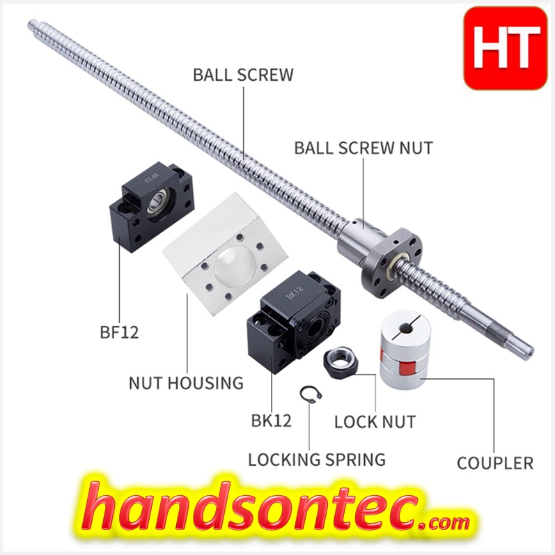
| 1 | Brass nut screwlead | 10 $ | 10mm |
| 1 | Leadroad | 5$ | 10mm |
| 20 | Screws | 2$ | M3 |
| 20 | Nuts | 2$ | M3 |
| 2m | Aluminum profiles | 22.00 $ | 20x20mm |
| 1 | PLA Spool | 25 $ | techworks |
| 1 | Arduino Uno | 25$ | Arduino board |
| 1 | Driver | 10$ | stepper driver |
| 1 | Stepper Motor | 10$ | 40x40mm |
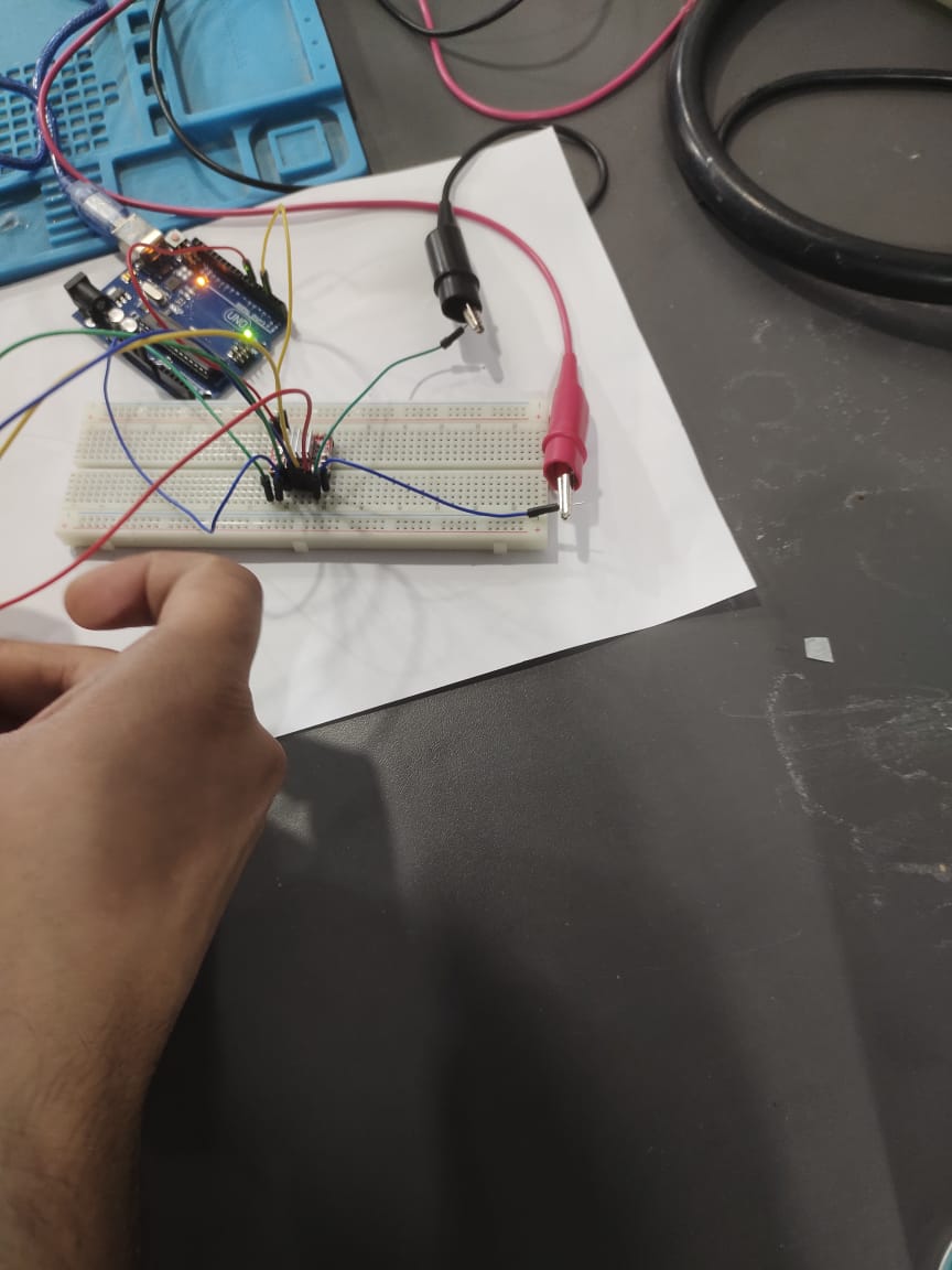
Electronics
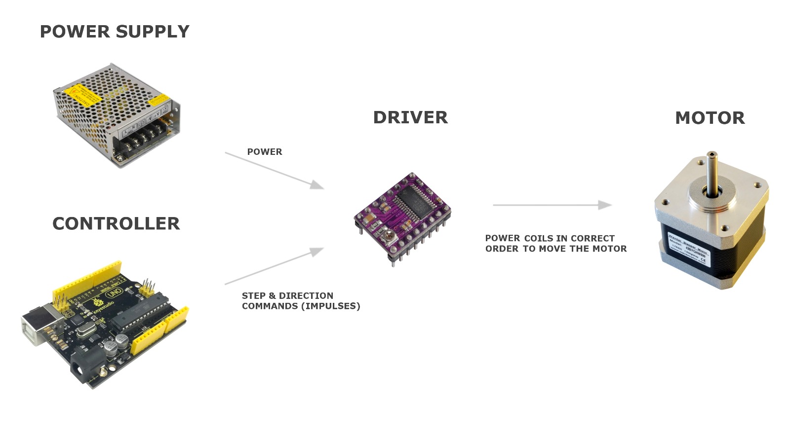
- Components needed to automate the wool picking machine with Stepper motor
Process
Designing the wool picker brush platforms involves creating a 3D-printed model with 45-degree angled nail holes. Simultaneously, a digital model for a laser-cut box is crafted for precise cutting and easy assembly. The 3D printer transforms the wool picker brush design into physical platforms, and nails are manually inserted. The laser cutter then processes the digital box model, producing flat pieces for assembly. This dual approach seamlessly combines 3D printing and laser cutting, optimizing the functionality of the wool picker brush and creating a precisely crafted box.
Steps
-
Design and Planning:
-
Define the specifications and requirements for your wool picker machine, including the size, capacity, and speed.
- Sketch a design that includes the frame, motor placement, picker drum, feeding mechanism, and any additional features.
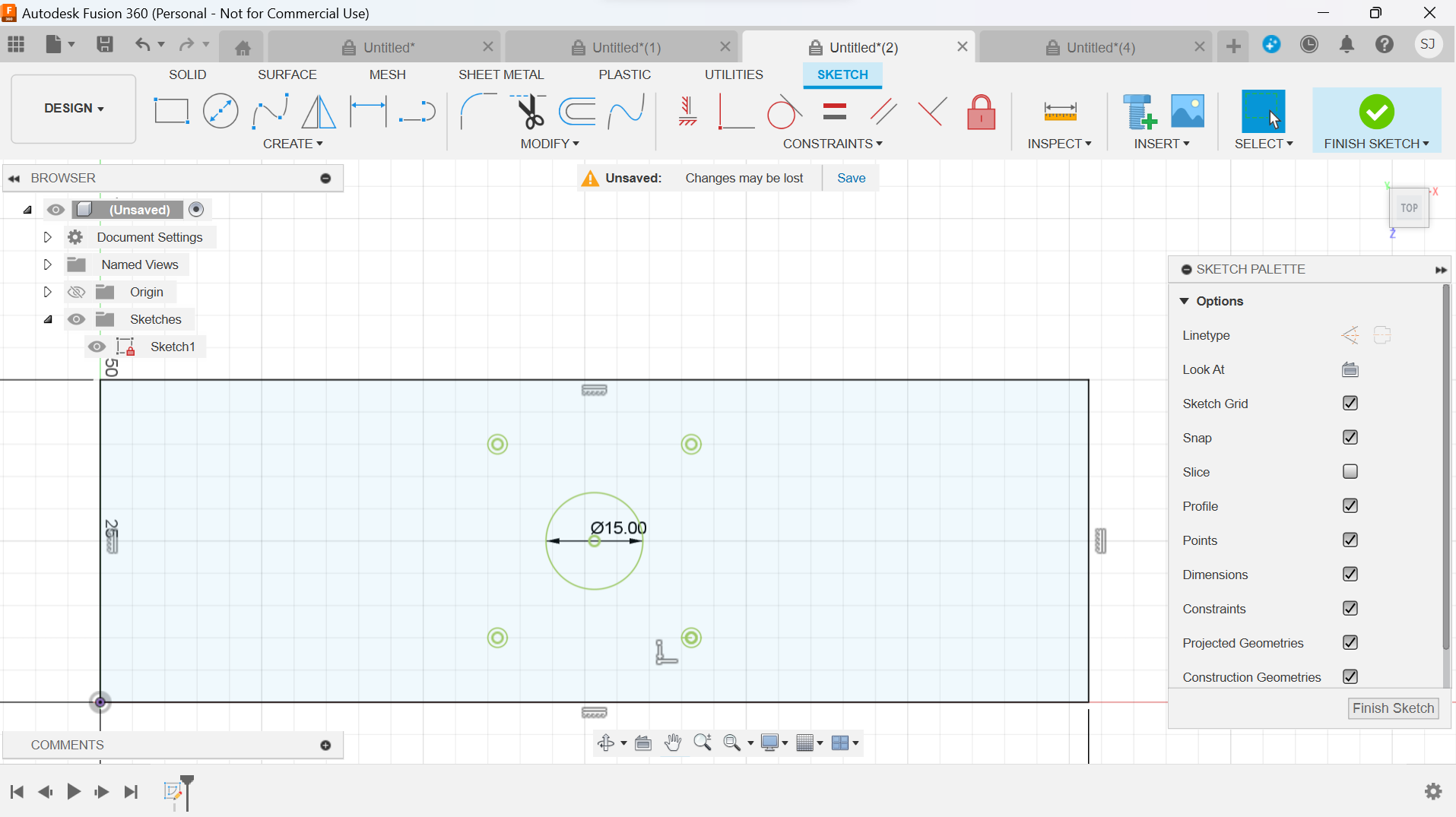
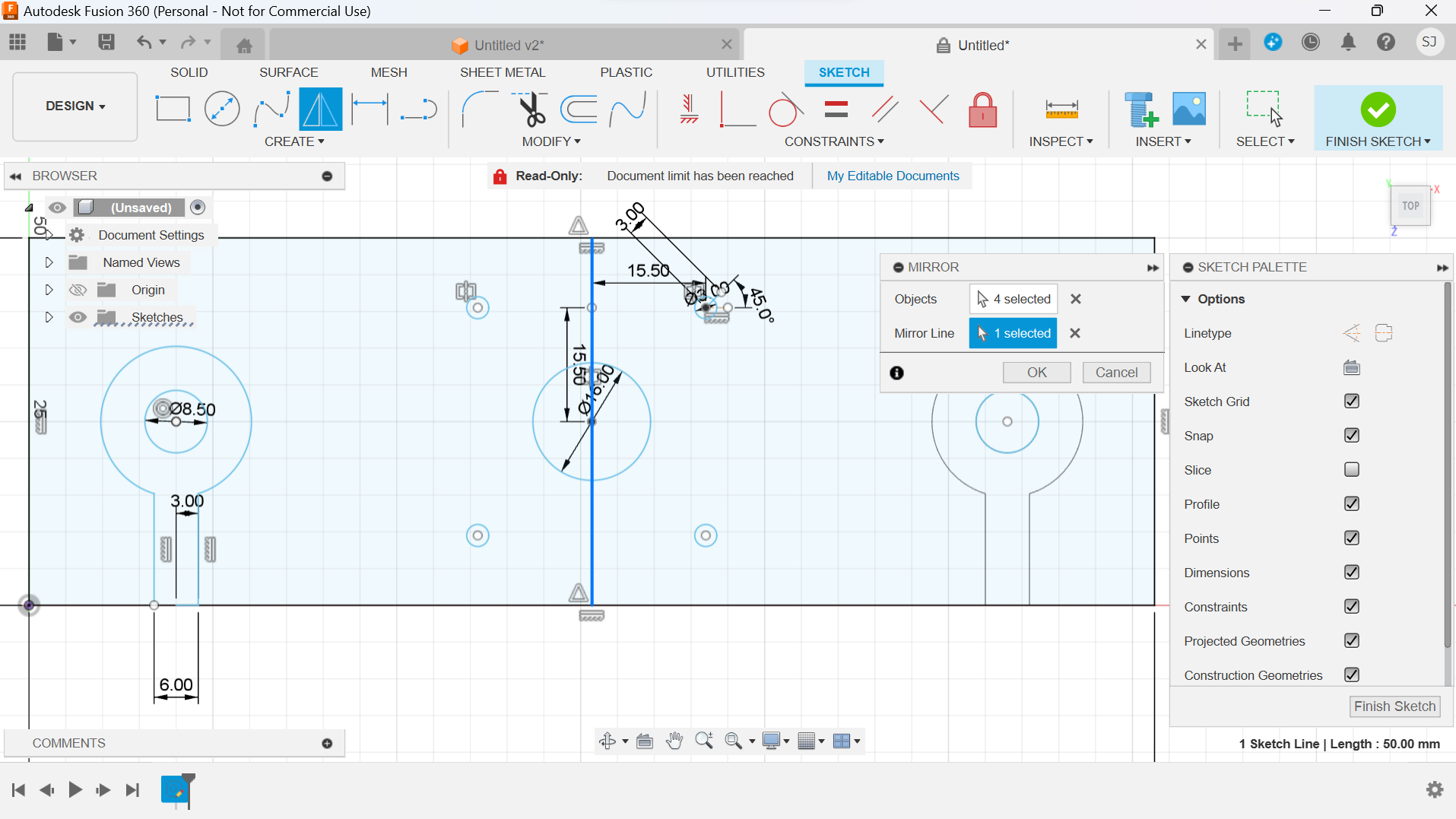
We designed the 2D model of the structure in Fusion 360 through sketch, lines and mirror commands, then we tested it with a lasercutter to see if the size fits each hole.
Laser cutting settings for MDF 3mm to test different diameters for screws and lead roads:
Power: 100 Speed: 0.2
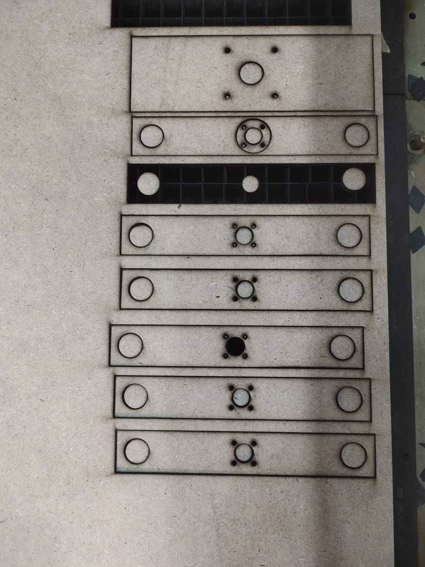
- We have the 3D shape of the test for the pieces of the machine for the lead road and brass nut screws. We glued the designed parts with wood glue and let it dry 3hours
- Assembly of structure and electronics together
3D Printed parts
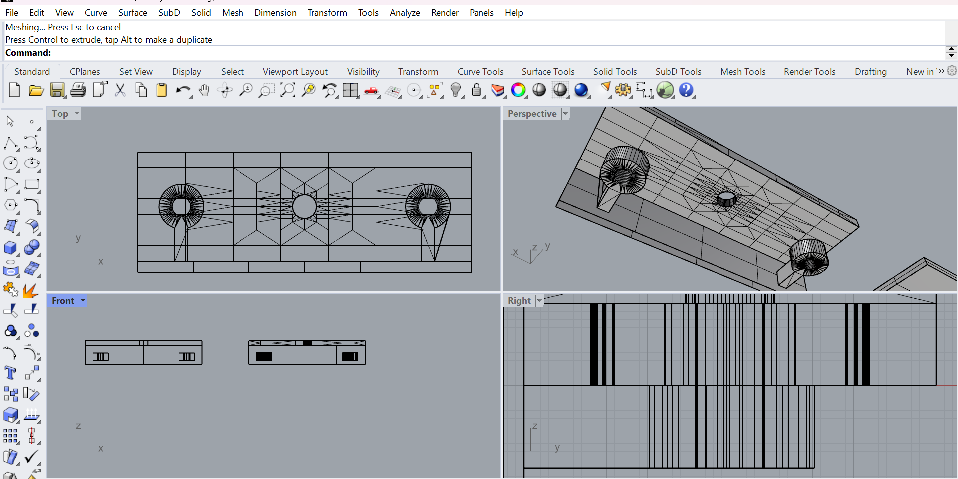
Design in Rhinoceros:
Once we agreed with the dimensions, we designed another version of the parts in Rhino creating extrusions and the holes for the electronics components.
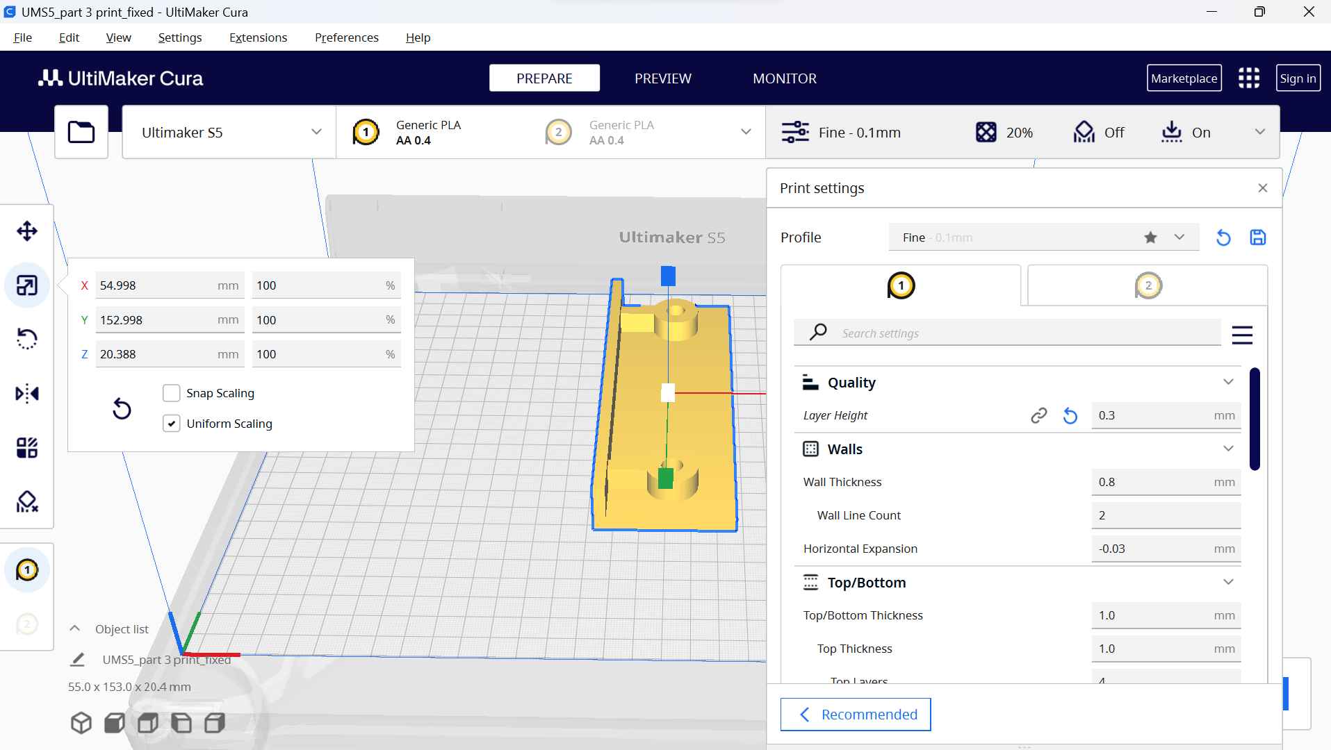
Then we exported as STL and upload the design in the Cura sofrware for 3d printing.
We printed all parts in white PLA.
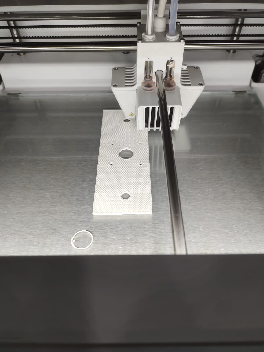
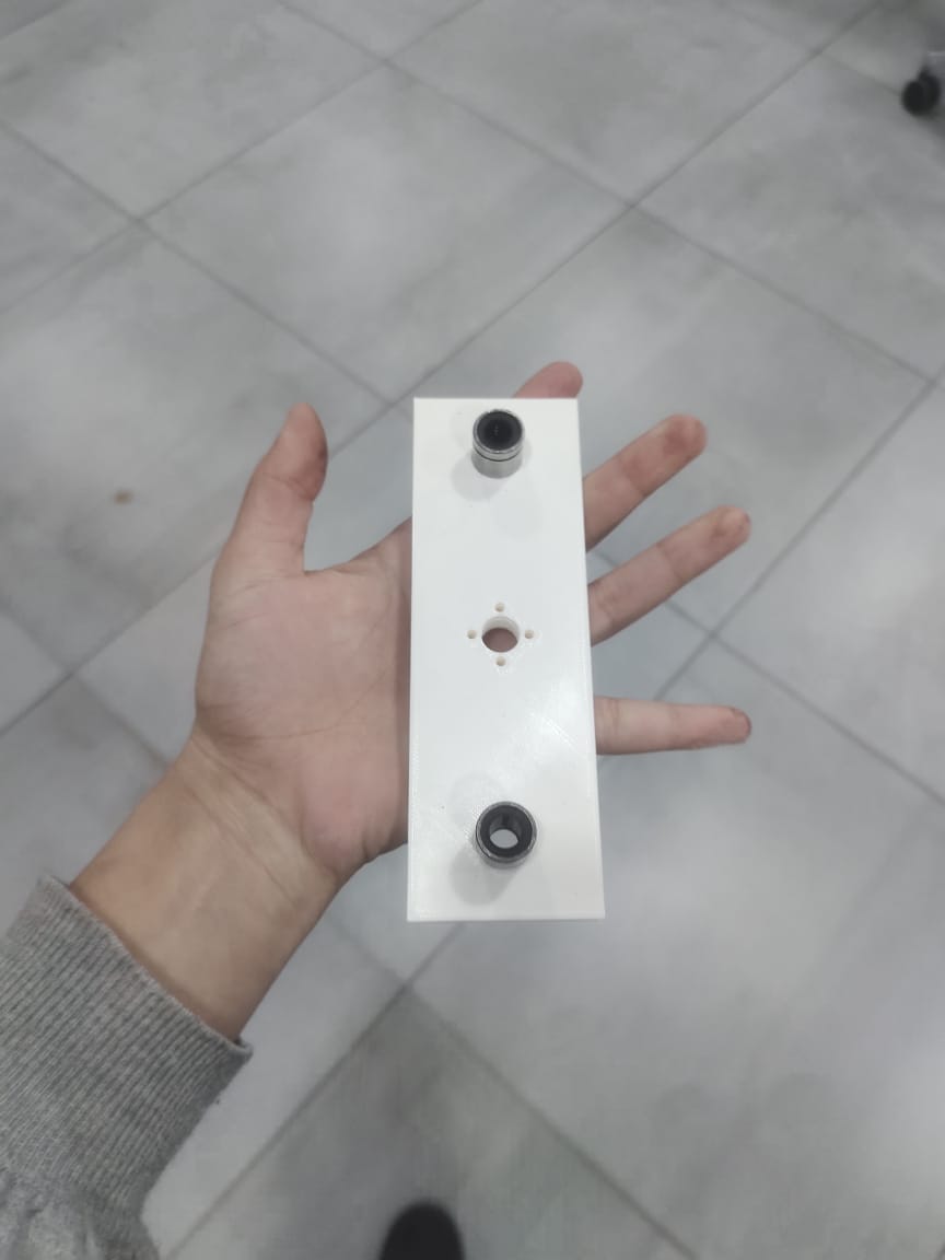
- Testing the printer part with screws, nuts and lead road. All good.

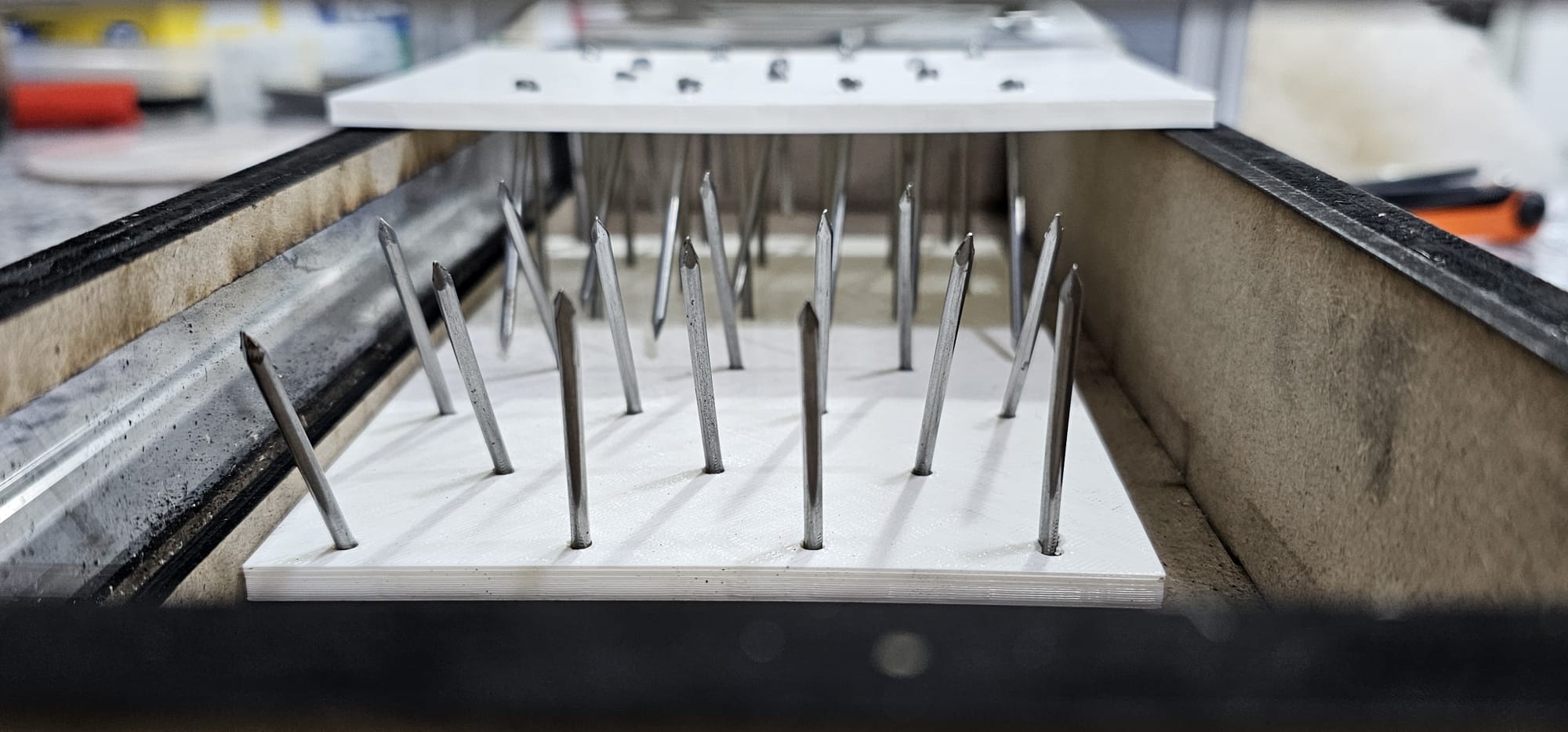
Meanwhile in Rhino we designed 2 small parts to include the nails that have to be oriented 45 degrees to be able to open the fibers of the wool when in action.
Creating a digital model with nail holes angled at 45 degrees. The 3D printer translates this design into physical platforms, incorporating the specified nail holes. Once the printing is complete, the next step involves inserting nails into the designated holes. This approach ensures precision in the placement of the nails, optimizing the functionality and effectiveness of the wool picker brush.
We followed the same workflow, exported the model in STL, then sliced and printed in PLA with the same settings.
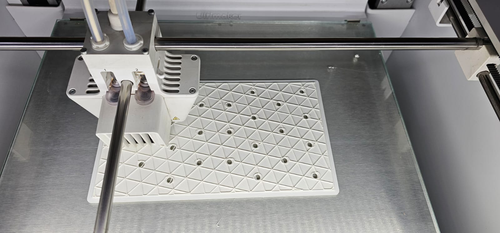
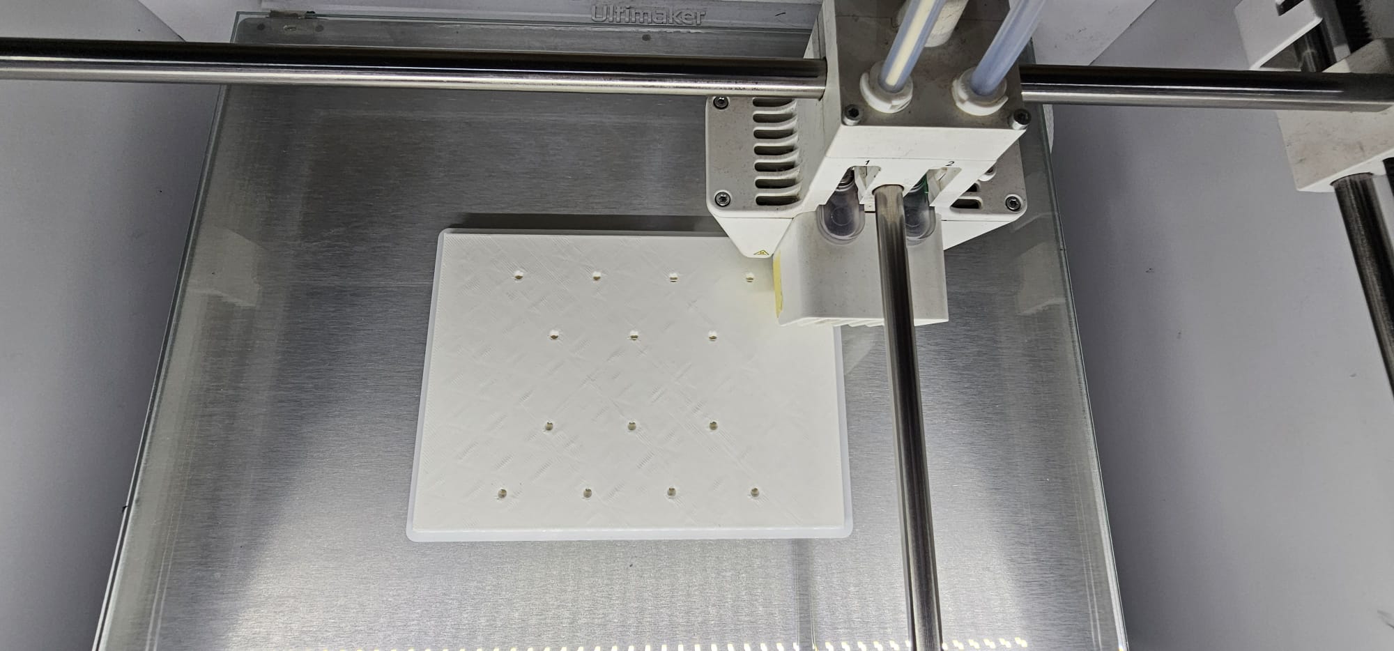
We inserted the nails in the holes with the help of hammer. The parts are ready to be tested.
Box
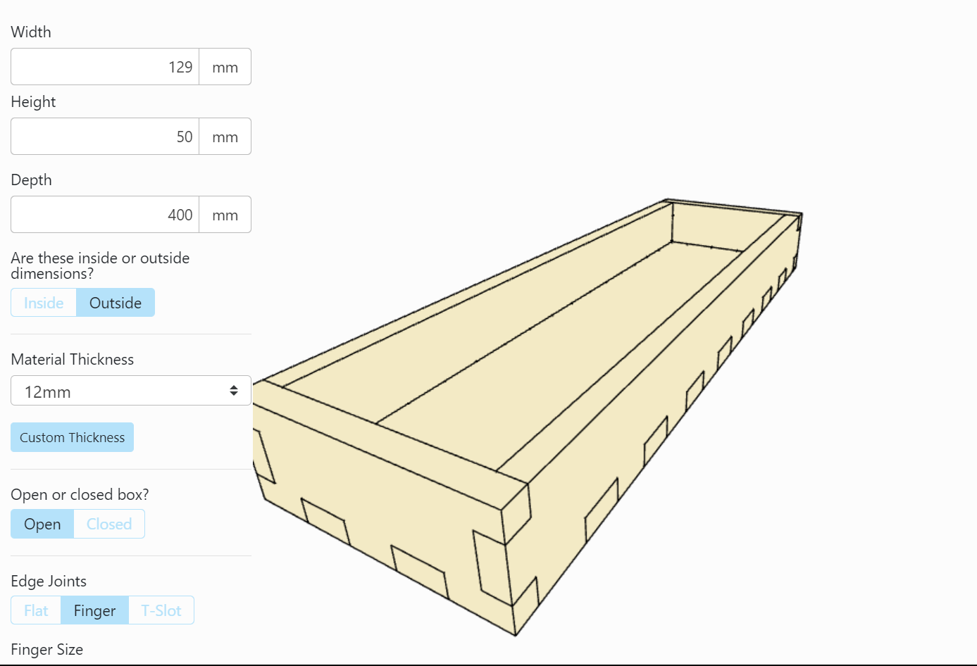
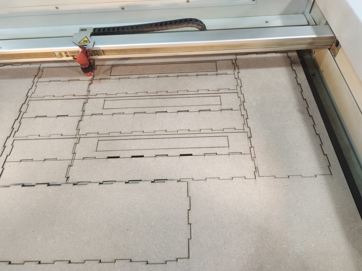
We decided to make a box to support the structure of the machine and collect some dirtiness from the wool with the box maker online software. We chose the sizes we needed: 129 mm in width, 50 mm in height, and 400 mm in depth. We then chose the finger joint we needed, and we had the out box of the machine. We printed it in the laser machine with the following settings on MDF wood.
Then we connect each piece together to give us the thickness we need with super glue.
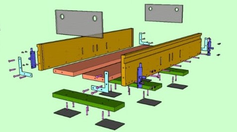
Aluminum structure
Gather Materials:
- Acquiring materials such as wood or metal for the frame, a motor with appropriate specifications, gears, a picker drum, spikes or teeth for the drum, bearings, and other necessary components.
Build the Frame:
- Construct a sturdy frame based on your design. Ensuring it provides stability and support for the moving parts. This is the foundational structure for your machine.
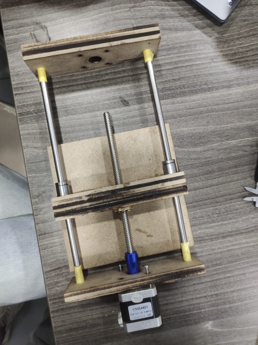
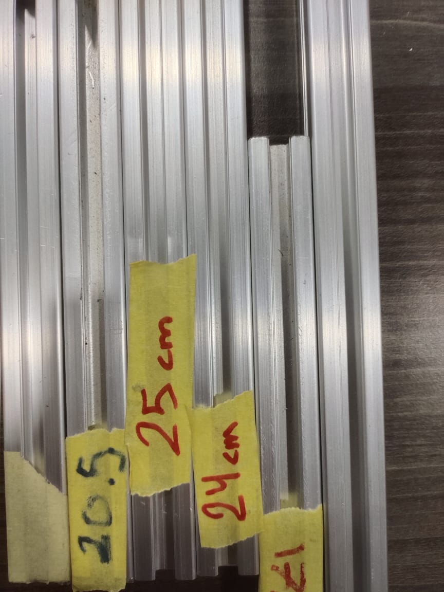
We use these aluminum parts we found in the lab for the wire frame to connect the structure.
We measure each one and connect it to the screw and the nut together with the corner and screwdriver to tighten each screw.
We cut each of them with the bandsaw machine of the lab and we assemble the parts together with screws and aluminum corners to keep the parts aligned.
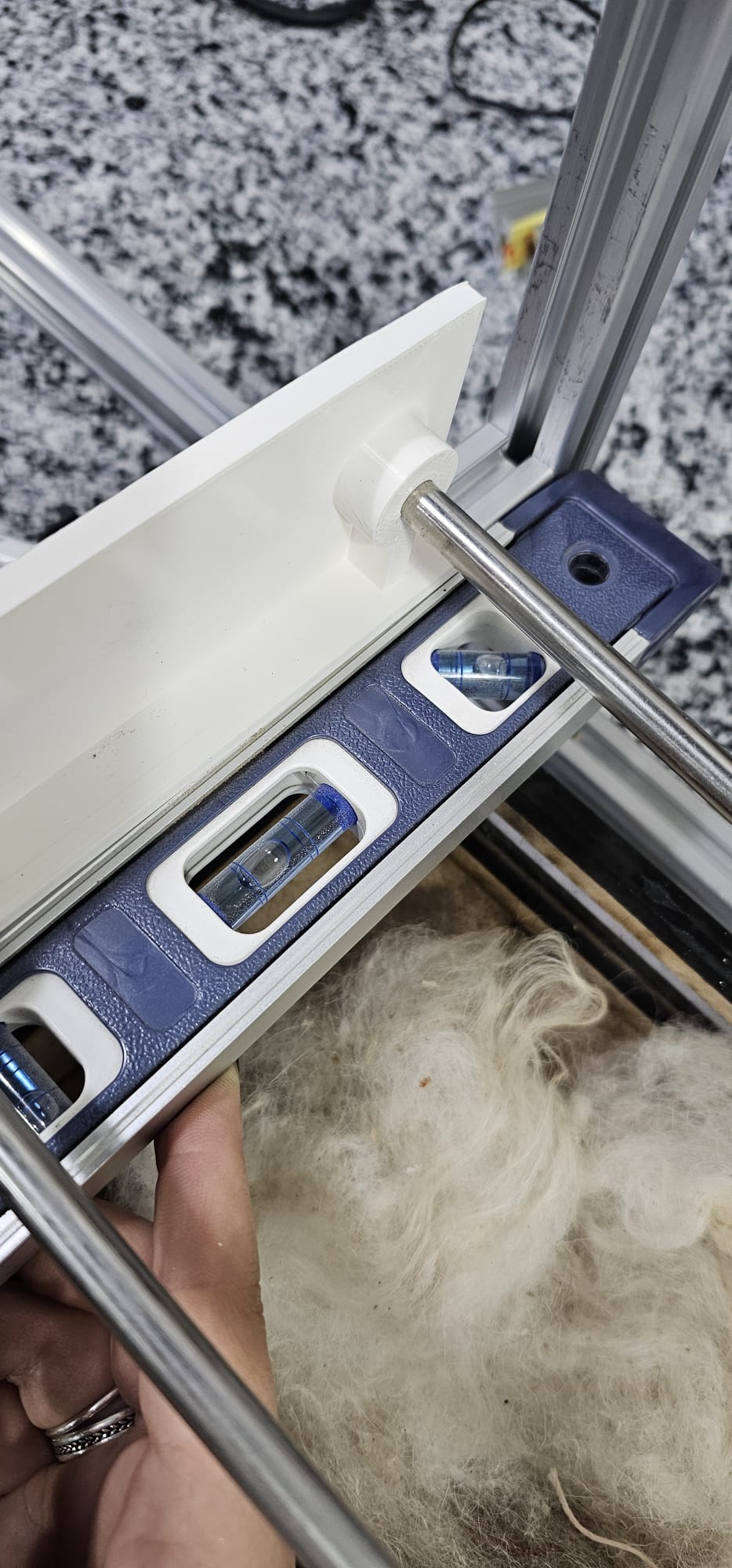
We used the levelling tool to check alignments.
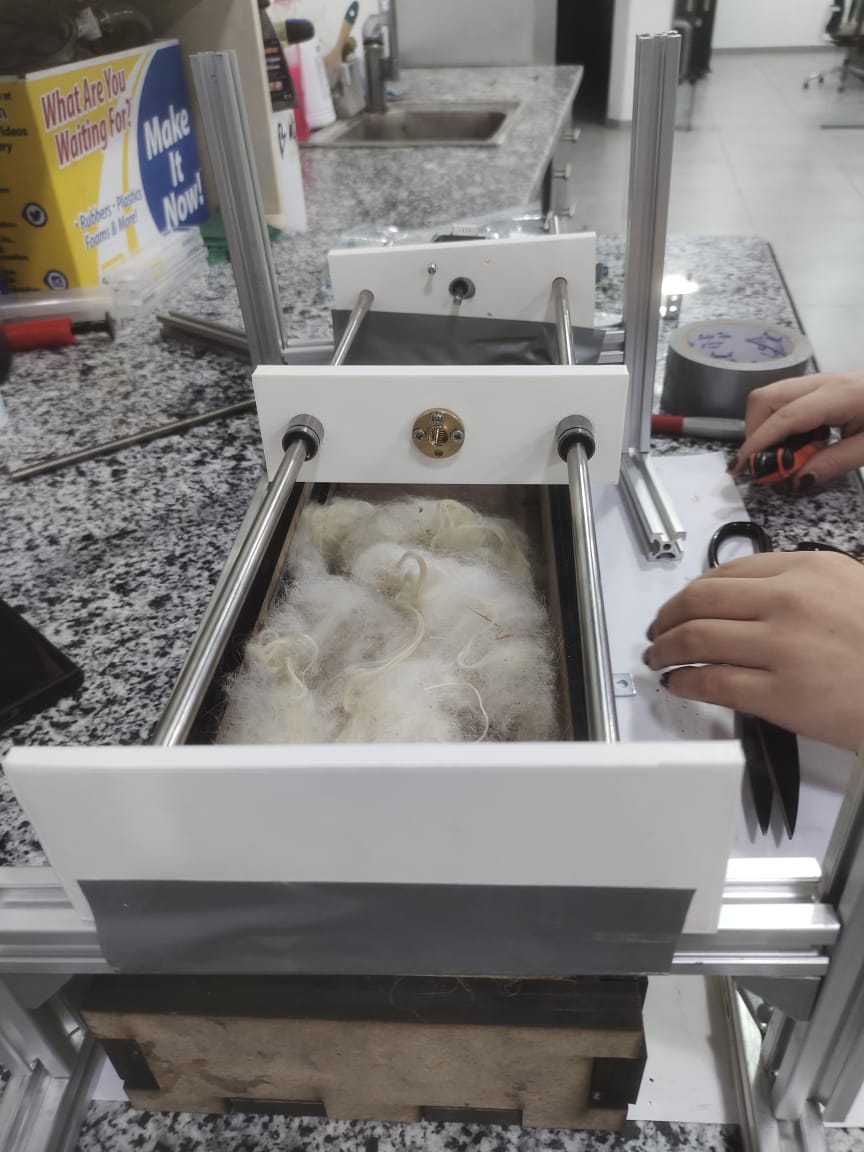
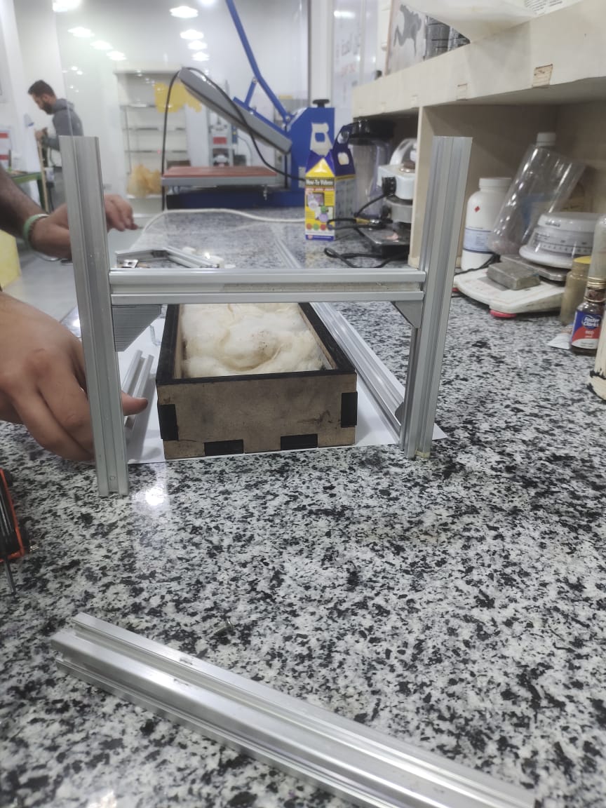
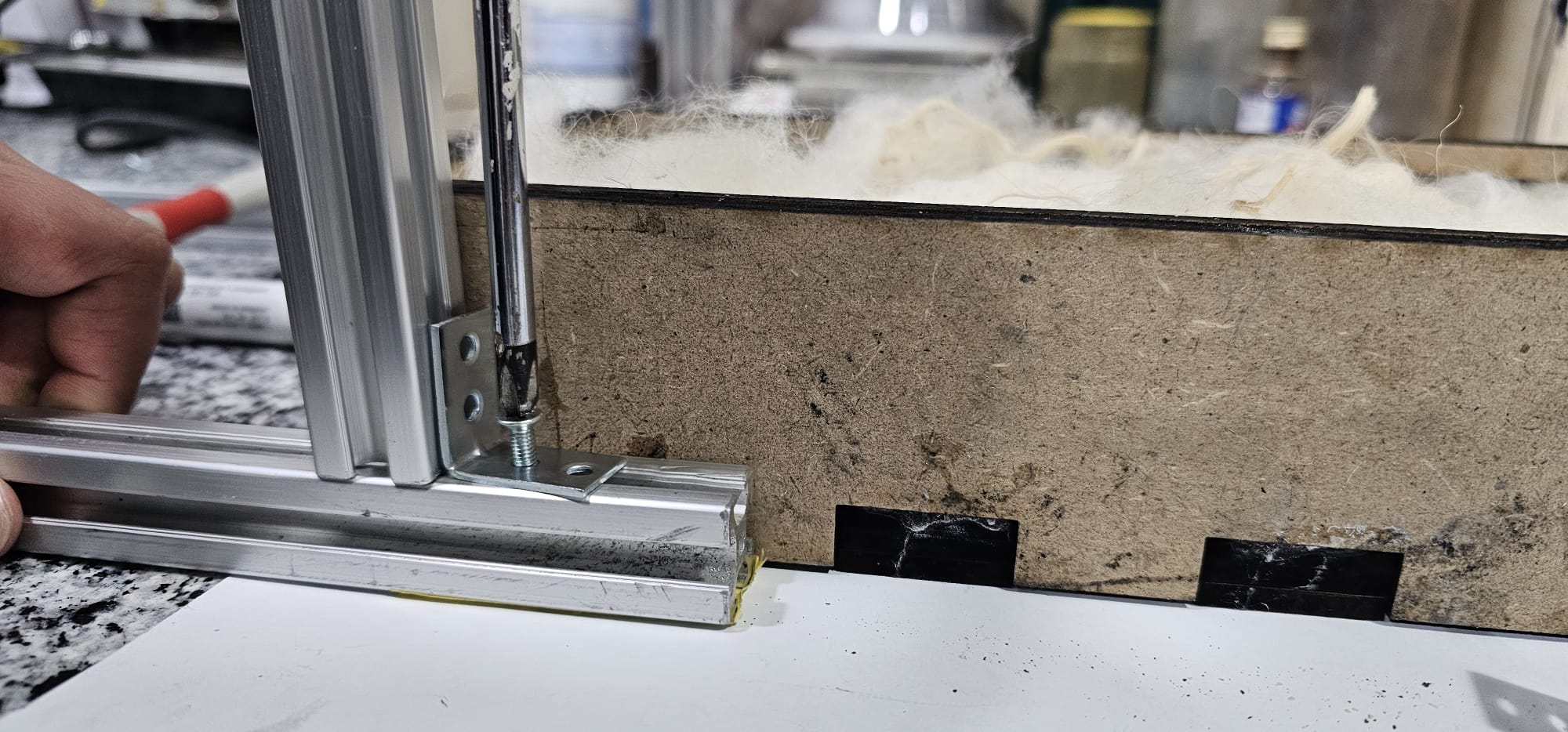
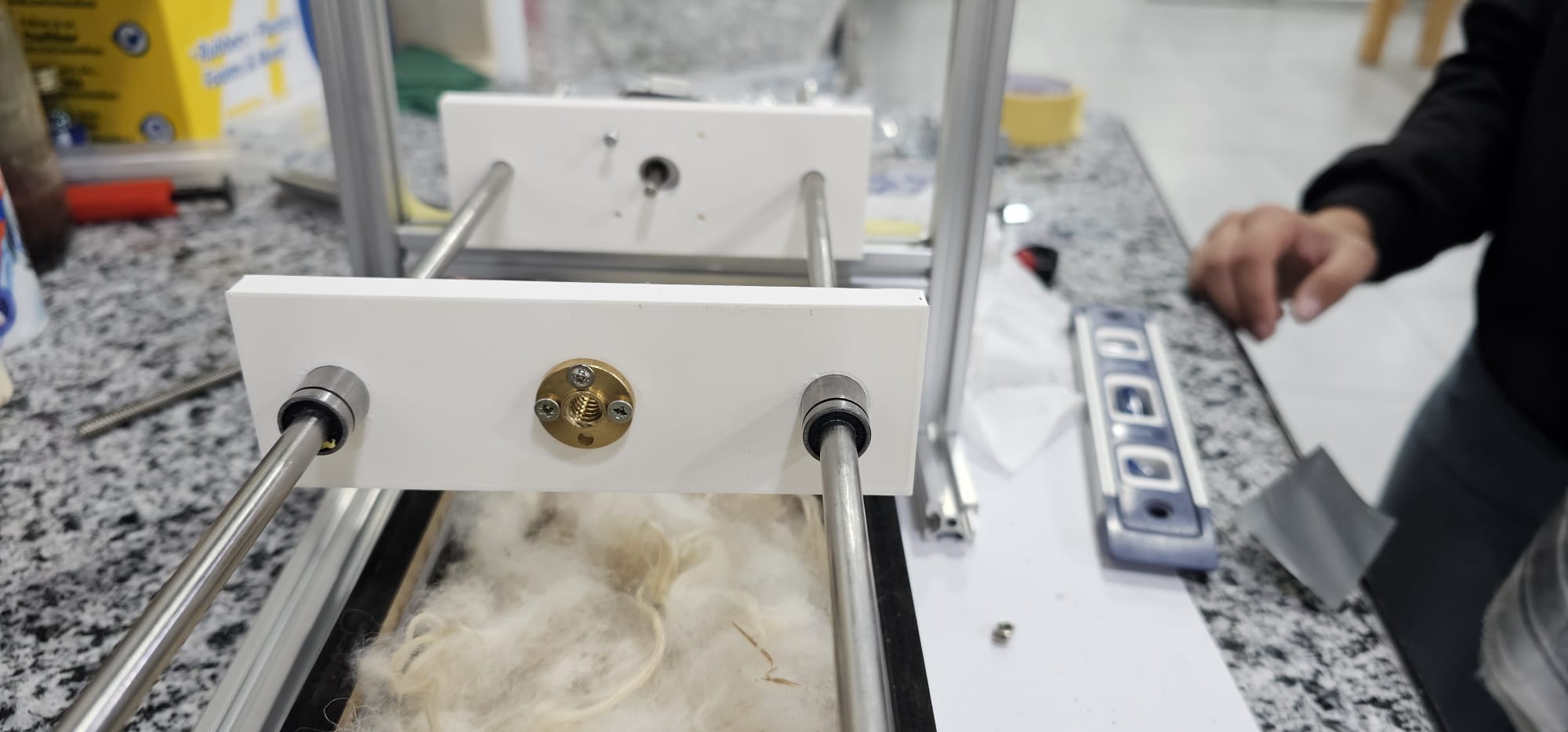
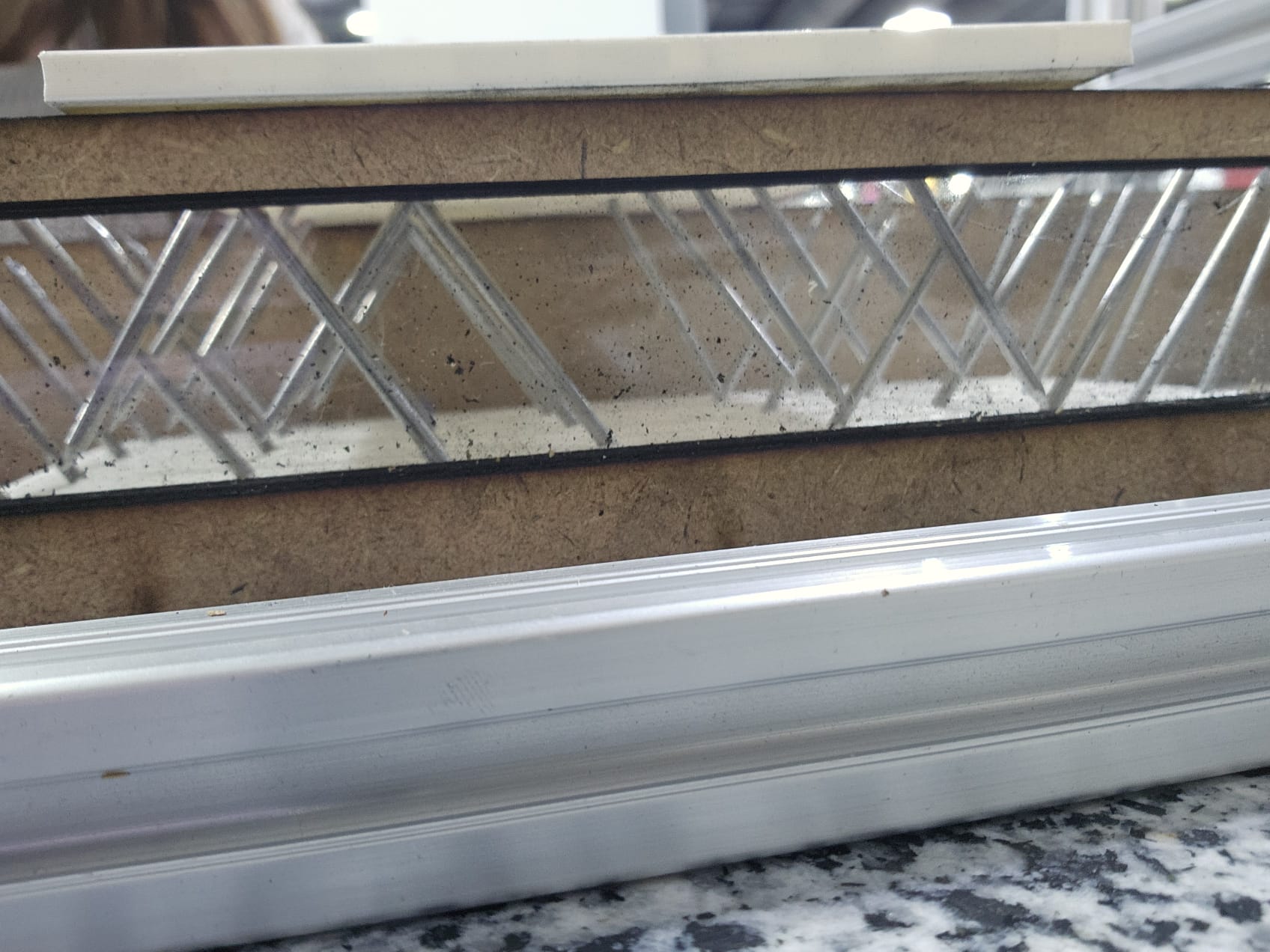
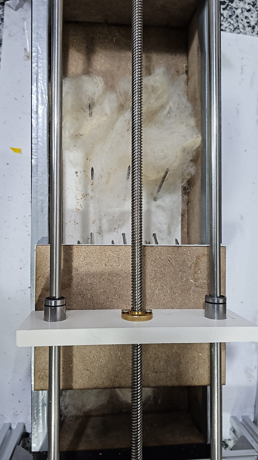
- Final asset of the machine with 3d printed parts and wooden box together for testing.
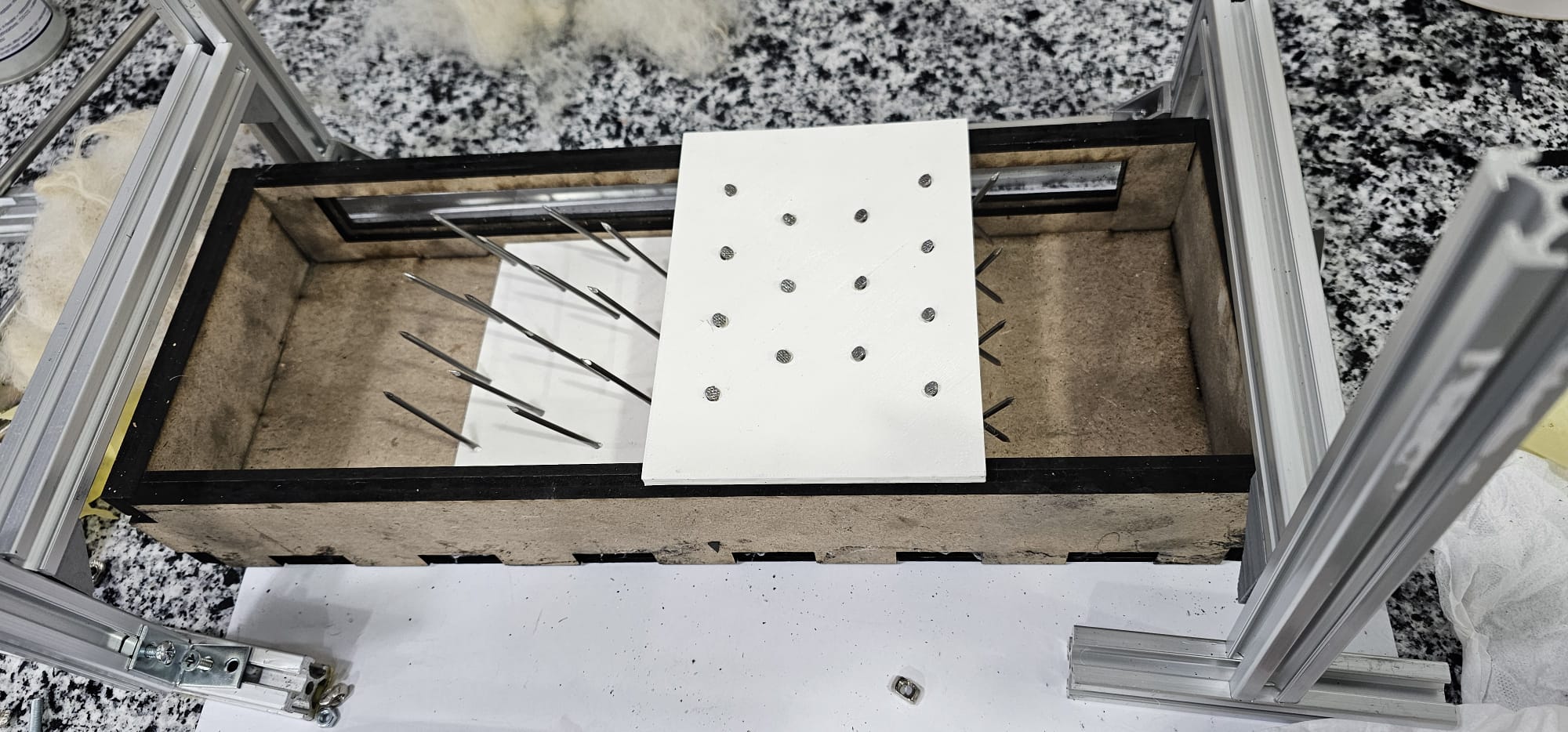
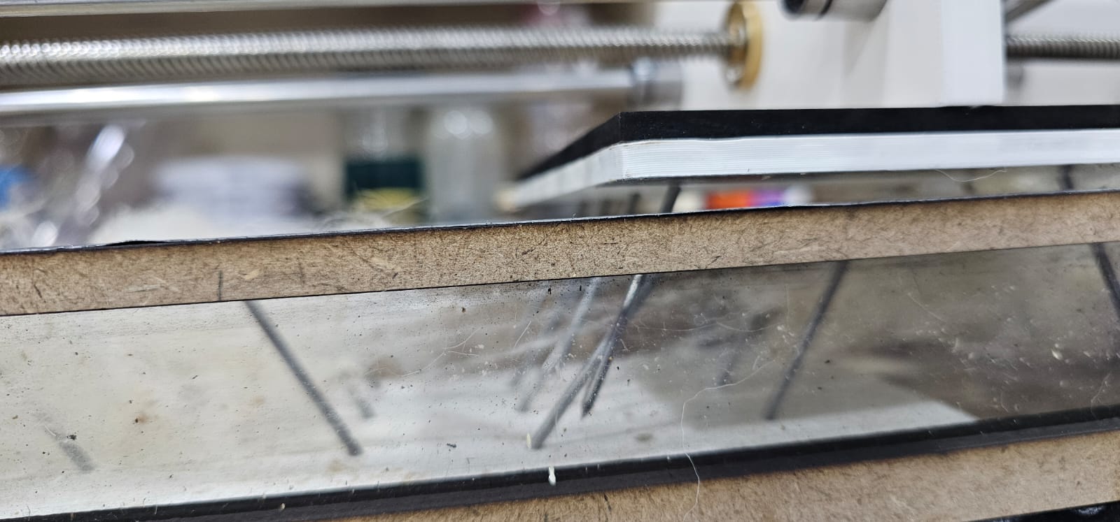
- Testing the gap between the 2 plates and the nails.
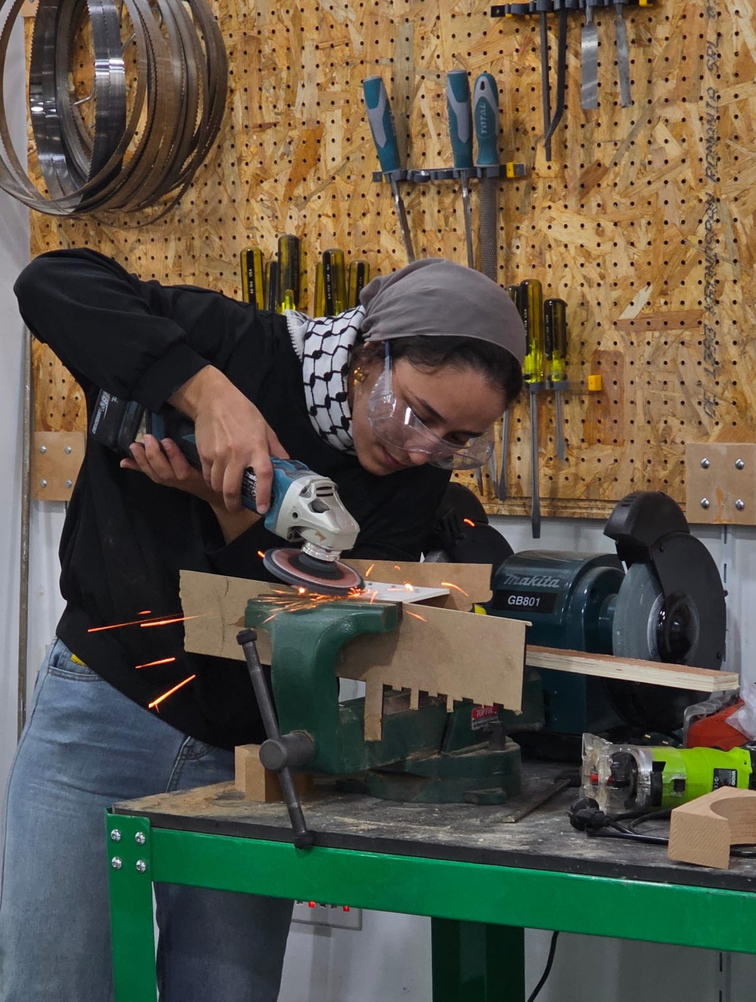
I used the grinder to polish the top of the nails to be flat.
Powering the machine by a drill
We replaced the stepper moto with the drill because of the higher power of the motor.
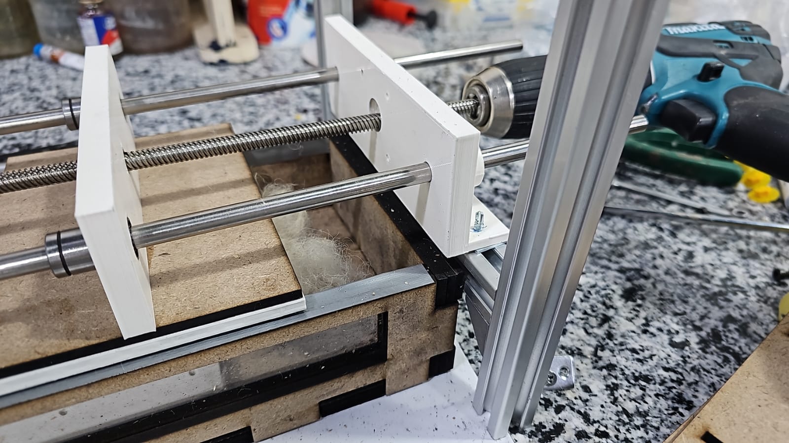
After testing the machine with the drill, we achieved a better result and a lot of dirtiness from the wool came out.


Final Result

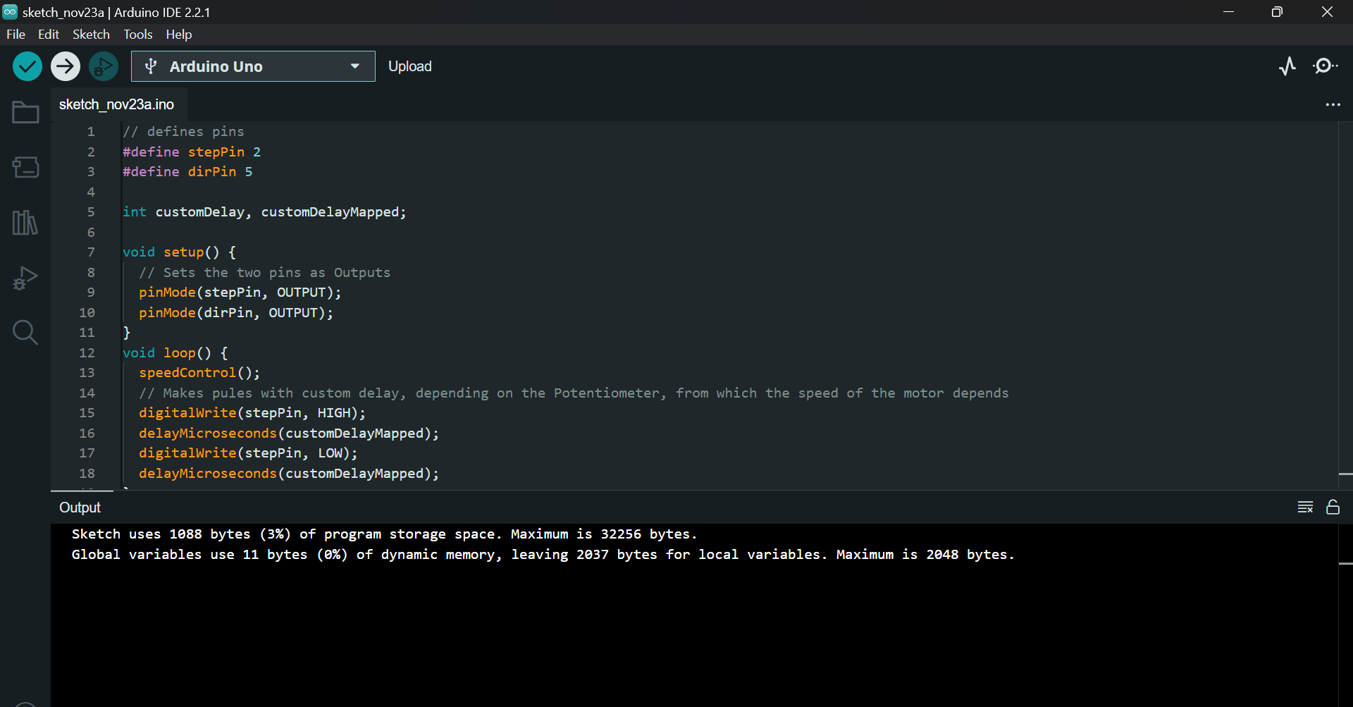
Code Example
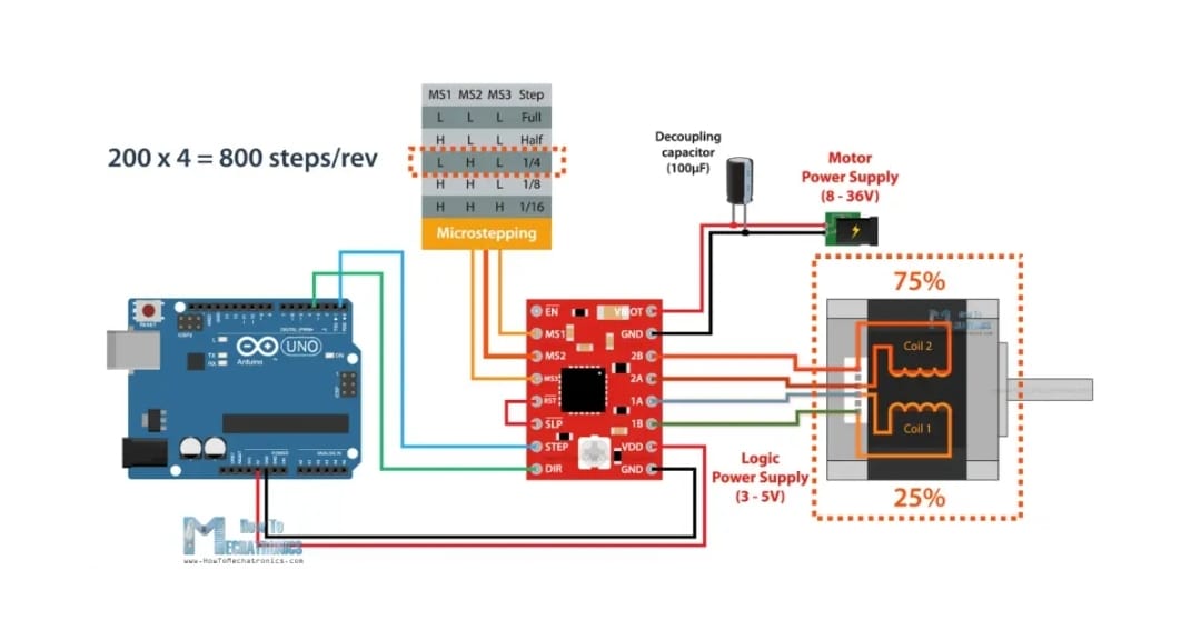
This is the code we use connecting the Arduino board to the stepper motor, the driver and power supply, according to the schematic below.

// the setup function runs once when you press reset or power the board
void setup() {
  // initialize digital pin LED_BUILTIN as an output.
  pinMode(LED_BUILTIN, OUTPUT);
}

// the loop function runs over and over again forever
void loop() {
  digitalWrite(LED_BUILTIN, HIGH);   // turn the LED on (HIGH is the voltage level)
  delay(1000);                       // wait for a second
  digitalWrite(LED_BUILTIN, LOW);    // turn the LED off by making the voltage LOW
  delay(1000);                       // wait for a second
}
3D STL PART OF THE MACHINE
Part A :
The 3D printing parts for the machine are:
Part B:
The box from MDF wood is 4 mm thick; we use a 12 mm total thickness; we put 3 layers together as.
This is the file attached as a PDF file for printing the box here.