7. Computational Couture
Research & Ideation
DEFEXTILES: is a rapid and low-cost technique to produce tulle-like fabrics on unmodified fused deposition modeling (FDM) printers.
mission
the assignment is to:
- learn how to use parametric design with the Grasshopper or other CAD software
- experiment with 3D printing, either on fabric, or printing a structure alone
parametric resources
3D printing resources
- What is 3D Printing?
- Digital Designs for Physical Objects
- 3D Models
- 3D Printing with living organisms - MIT video
- 3D Printing Forum
- Prepare file with CURA for printing
- Guide - 3D Printing on Fabric for Designers free download
- Easy tutorial by Sara Alvarez video
- 3D Printing on Fabric — Tips, Tricks, and Code
- How to 3D Print on Tulle Fabric instructable
- 3D Printing Troubleshooting
References & Inspiration
For me it remains an open question whether (this work) pertains to the realm of mathematics or to that of art.
M.C. Escher
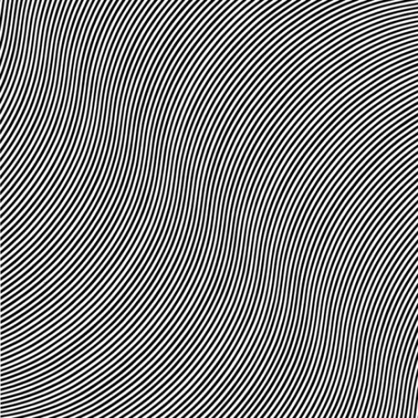
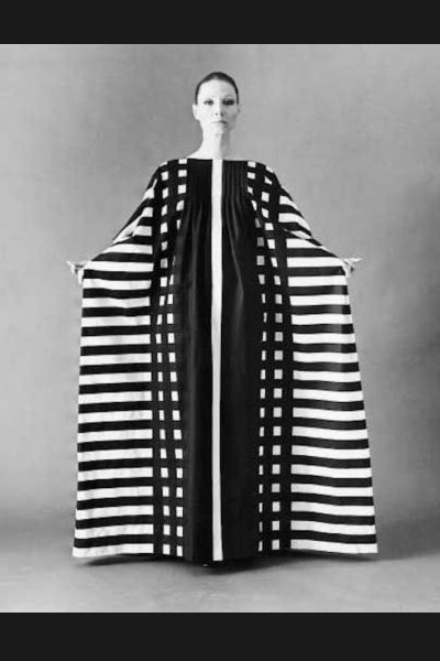
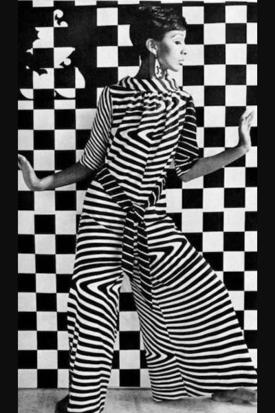
Op Art is an abbreviation of optical art, a form of geometric abstract art, that explores optical sensations through the use of visual effects such as recurring simple forms and rhythmic patterns, vibrating colour-combinations, moiré patterns and foreground-background confusion. A type of abstract Art that exploits certain optical phenomena to cause a work to seem to vibrate, pulsate, or flicker. It flourished mainly in the 1960s; the term was first used in print in the American magazine Time in October 1964 and had become a household phrase by the following year, partly through the attention given to the exhibition ‘The Responsive Eye’ held at the Museum of Modern Art, New York, in 1965. Formally, all Op Art paintings and works employ tricks of visual perception like manipulating rules of perspective to give the illusion of three-dimensional space, mixing colours to create the impression of light and shadow.
Key period: late 1950s and 1960s Key words: visual illusion, illusion of movement, repetitive forms, checkerboard patterns, tension, complementary colours, kinetic arts Key artists: Victor Vasarely, Bridget Riley, Richard Anuskiewicz, François Morellet, Jesús Rafael Soto, Julio Le Parc, Gianni Colombo, Peter Kogler, M.C.Escher, Josef Albers
Art Inspirations

Fashion Tech Reference
about the images..
from left to right, top to bottom:
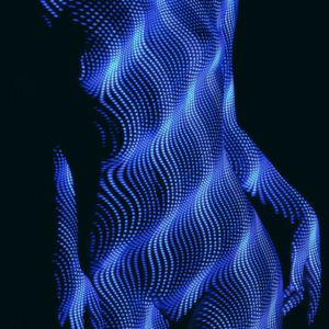
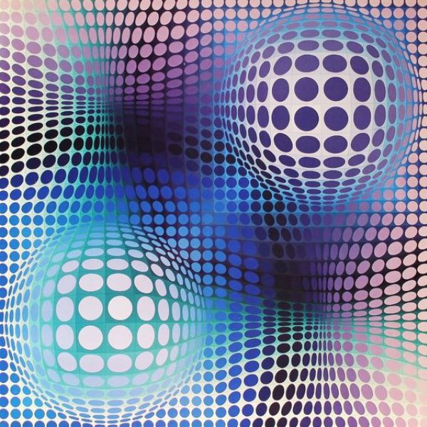
- Victor Vasarely
- Sofie di Bartolomeo - A Matter of Tactility - Sensorial Fabrics,2018
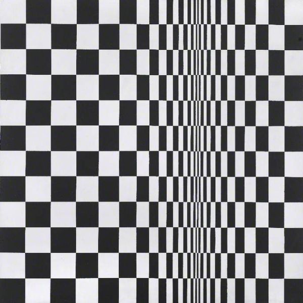
- Bridget Riley - Movement in Squares, 1961
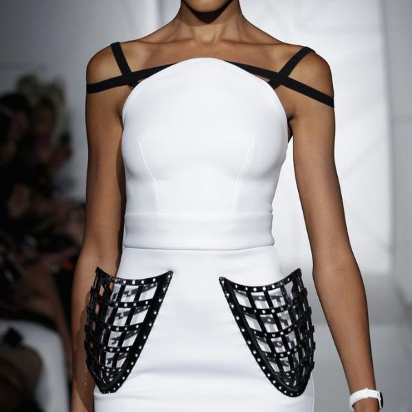
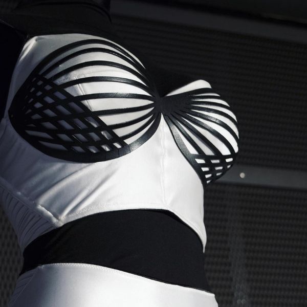
- Chromat Formula 15 Collection- SS'15, 3D printed
- Bridget Riley - Over, 1966
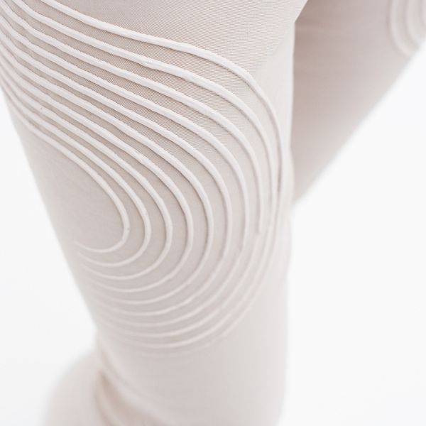
- Lidewij van Twillert - Contour Bustier, 2019
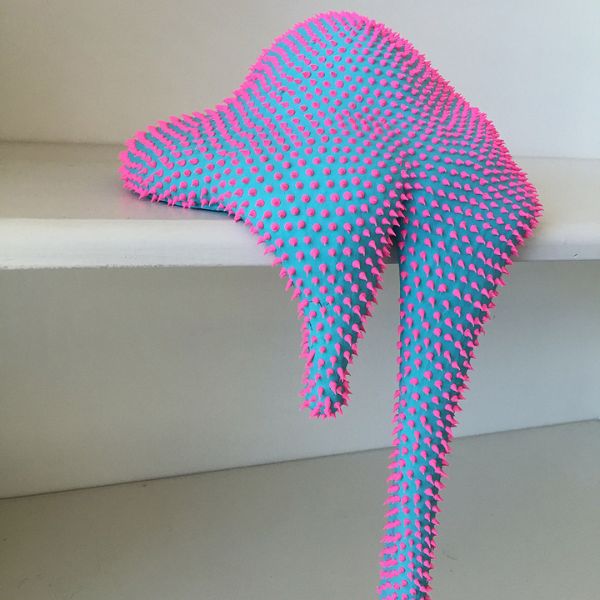
- Dan Lam - Oozing sculpture, 2016
- Victor Vasarely - Sharing Shapes, 1976
Tools & Software Resources
- Grasshopper - How to install Plugins
- Parametric House - Grasshopper Tutorials
- Grasshopper Glossary & How-tos
- Tutorials for Basic Exercices in Grasshopper
- Tinkercad - CAD free software online
- SketchFab - 3D viewer online
Process and Workflow
Parametric modelling
Parametric modeling is a modeling process with the ability to change the shape of model geometry as soon as the dimension value is modified. There are several CAD (computer aided design) softwares available: open-source and/or online. I dove into the odyssey of trying to figure out how Grasshopper works. It's a very complex software and will take a lot of time and practice to realize its capabilities and functions. Meanwhile I made a quick search and found plenty of nice tutorials and guides for beginners. I started by getting to know Grasshopper's interface and basic operations.
Learning the basics
In order to create a pattern I had to understand some basics of parametric modeling and the right steps to make it.
- UNIT CELL: if the cells are colored in, this means they are a surface and can be baked
- GRID: the design of the tile uses a grided array of elements
- ARRAY: is a group of similar elements or data items of the same type collected at contiguous memory locations
- TILING:
- EXTRUDING:
- MESH: is a collection of quadrilaterals and triangles that represents a surface or solid geometry. This structure is simply a collection of points which are grouped into polygons. The points of a mesh are called vertices, while the polygons are called faces. It is possible to convert breps and surfaces into meshes
- SURFACE: it consists of a single smooth area but may have custom edges. If a surface is just a (deformed) rectangle and it has no custom edges, it is called an 'untrimmed' surface. Surfaces with custom edges or holes punched into it is called a 'trimmed' surface
- BREP: is one or more surfaces joined together. If a brep only contains a single face, then it is the same thing as a surface. For surfaces to be joined together into a brep, they need to share some of their edges
- PANELING: can be define as ways to shuffle grid point locations or. distribute variable components based on attractors. Paneling in the context of PanelingTools plugin refers to the process of mapping geometry or modules to a rectangular grid. Paneling can be either along one grid to generate 2D patterns or between 2 bounding grids to generate 3D patterns
- ATTRACTORS: can be points, curves, surface curvature or other methods. Attractor components calculate the weights of corresponding input grid and output.
So based on this concepts I defined my workflow to design a pattern to 3D print. There are several ways to design a pattern but the basic steps include:
1. create a unit CELL/shape
2. array the shape so it creates a tile pattern
3. extrude it
or
1. create a grid pattern according to attractor curve
2. extrude it
It's all about practice so I made some exercices following these nice examples that I found online:
- DOMAIN BASICS (construct, bound and deconstruct a domain, remap number, gradient an input, custom preview)
- PARAMETRIZATION (remap numbers to a set of fixed target values and to shuffle the results utilizing the Jitter Strength input)
- USE ATTRACTORS (using multiple points and curves attractor to build a parametric pattern)
- COLLIDE LINES (grasshopper kangaroo plugin to make a parametric pattern using the sphere collide and length(Line) component)
- VENATION PATTERN (build a venation pattern produced by random points and or defining multiple point attractors with Shortest Walk Plugin)
- MAGENTIC FIELD (making magnetic field lines).
- GRID DISTORTION (drawing a geometric grid and extruding it)
- PATTERN GENERATION (generate a pattern on Grasshopper)
This grid was my favourite:
Grid Distortion in Grasshopper Using Tensors
Step 1: Create a Pattern to Print
The first step of 3D printing typically starts on a computer. You must create your design using a 3D design software, typically a CAD (computer-aided design) software. If you are unable to create the design yourself, you can also find many free resources, above I list some of them:
Resources to Find a Design
- Youmagine
- Cults 3D
- Thingiverse
- CG Trader
- My Mini Factory
- PinShape
- NIH 3D
- 3DExport
- SketchFab
- 3D Warehouse
- Instructables
Design with Grasshopper
This model 1 was obtained by.. The paramteric model 2 was created using.. it allows the user to follow, shape, adapt, increase, mimic.
Step 2: 3D Printing Workflow
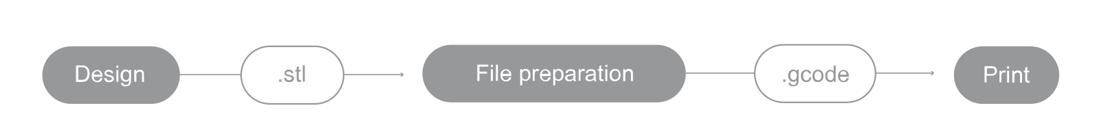
Depending on the specific print you are planning to do there could be more or fewer steps in your process. But in general, 3D printing involves the following actions:
-
Export the STL File Once you have created or chosen a design, you must either export or download the STL file. The STL file is what stores the information about your conceptual 3D object. Learn how to do it in Grasshopper here
-
Choose the filament There are many different materials available and you can find them on this materials guide) for 3D Printing and a filaments properties table. I'll be working with flexible filament TPU - Thermoplastic polyurethane.
-
Choose your parameters The next step is then deciding on the different parameters of your object and the printing process. This includes deciding on the size and placement of your print.
-
Create the Gcode You will then need to import the STL file into a slicing software, like BCN3D Cura or Ultimaker Cura. The slicing software will convert the information from the STL file into a Gcode, which is a specific code containing exact instructions for the printer.
-
Print This is when the magic happens! The printer will create the object layer by layer - additive method.
Tips for printing with TPU Filament
  1. Properly store the TPU to prevent it from absorbing moisture from the air and causing printing problems.

  2. Reduce the printing speed of the TPU to 25mm/s or less.

  3. Avoid retractions and reduce the retraction speed.

  4. Use 0.8 or 1mm hotends to ensure part stability during printing

  5. Reduce the wall line count and the infill percentage for more flexible parts

  6. For flexible prints chose: Concentric, cross, or cross 3D infill patterns
Tips for Infill and Shell
When it comes to 3D Printing, knowing the terminology is important. Two of the most important terms to know are Infill and Shell. While the shell of a part defines its shape and accuracy, infill is incredibly important in determining its performance. Infill is optimized for strength and print quality, and is always made up of a tessellating shape distributed over the area of a layer.
My final model for printing is ...
The STL model 3 was obtained by..
Print with file [^4] was created using..
footnote fabrication files
Fabrication files are a necessary element for evaluation. You can add the fabrication files at the bottom of the page and simply link them as a footnote. This was your work stays organised and files will be all together at the bottom of the page. Footnotes are created using [ ^ 1 ] (without spaces, and referenced as you see at the last chapter of this page) You can reference the fabrication files to multiple places on your page as you see for footnote nr. 2 also present in the Gallery.
3D Models
upload the 3d models of MakeHuman, Final 3d modelled body, 3D Scans, etc use the fabrication files at the bottom of the page to link and upload models, referencing them with a footnote
Videos
learn how to add video tutorials, inspirational videos and movies etc
From Vimeo
Sound Waves from George Gally (Radarboy) on Vimeo.