Table of Contents
12. Skin Electronics
References & Inspiration
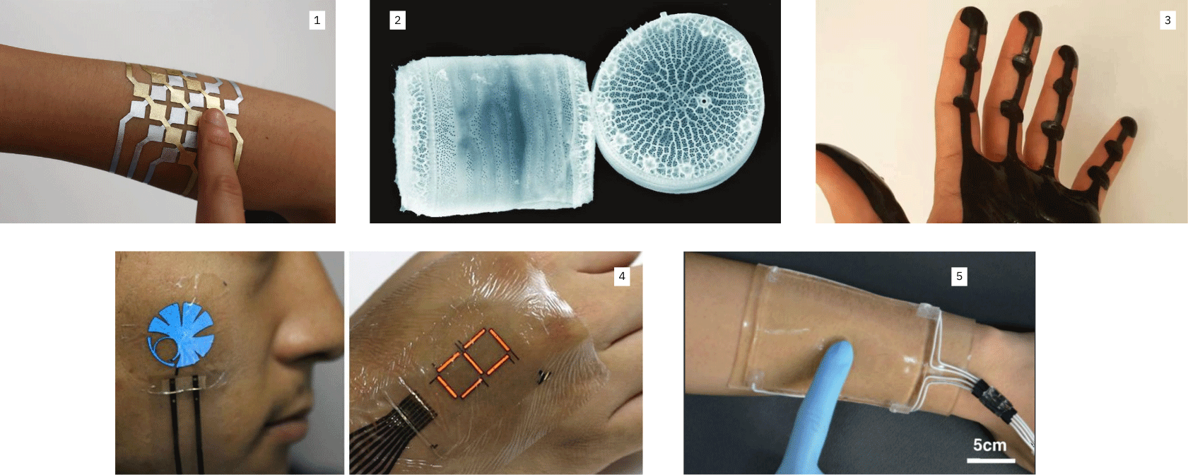
- DuoSkin is a metallic temporary tattoo material that serves as an on-skin interface with connected devices.
- A biosensor made of fluorescent proteins embedded in the shell of microscopic marine algae called diatoms that could help detect chemicals in water samples. (Sciencedaily)
- Magnetic skin that can be used to control a variety of devices using a simple magnetic sensor. (hackster.io)
- Ultra-thin flexible electronics with a display. (MHealthSpot)
- A new stretchable transparent touchpad can be used to write words and play electronic games. (Futuristech)
Tools
- Processsing
- alligator clips
- copper film
- gold leaf
- vinyl
- breadboard
- jumper wires
- ESPXIAO_S3
NFC
We tested the Near-field communication (NFC), which is is a set of communication protocols that enables communication between two electronic devices over a distance of 4 cm (1+1⁄2 in) or less. In the side video you can see me uploading the url on the NFC through the NFC Tools app.
- Open your application: Read > Scan your NFC
- Menu > Write > Add a record > URL / URI (Add a URL record) > paste your URL > OK
- Write > Write / 24 Bytes
Sensitive Matrix
We already prepared our Sensitive *Matrix for the afternoon workshop.
A matrix is a grid whose intersection nodes are sensors. In our application, pressure sensors. It allows you to use fewer pinouts but still have many pressure points.
Resistor → an electric component that can impede the amount of current. The analog sensor can act as a valuable resistor
| Resistors | what is it | Unit of measure | Testing | Voltage devider |
|---|---|---|---|---|
| ---------------- | an electric component that can impede the amount of current | Ohm | multimeter in resistance-measurement mode two resistors in a series | |
| can act as a valuable resistor | ---------------- | ---------------- | Vout = [ R2/ (R1 + R2)] x Vin |
Pull-up resistor → present in the pin of the microcontroller. To use it, you need to specify it in the code.
You can use a pin as an output, but you need to specify it in the code
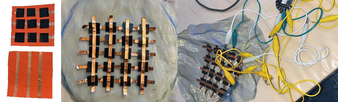
I first tried building my matrix on textile but the visuals I was obtaineing where not really clear. So I attempted again with paper, it was slighlty more reliable but not 100% working,
Arduino IDE
Sensitive Matrix 3r x 3c Arduino code 2
int row0 = A0;  //first row pin
int row1 = A1;  //second row pin
int row2 = A2;  //third row pin

int col0 = 9;    //first column pin
int col1 = 8;    //second column pin
int col2 = 7;    //third column pin


int incomingValue0 = 0; //variable to save the sensor reading
int incomingValue1 = 0; //variable to save the sensor reading
int incomingValue2 = 0; //variable to save the sensor reading

int incomingValue3 = 0; //variable to save the sensor reading
int incomingValue4 = 0; //variable to save the sensor reading
int incomingValue5 = 0; //variable to save the sensor reading

int incomingValue6 = 0; //variable to save the sensor reading
int incomingValue7 = 0; //variable to save the sensor reading
int incomingValue8 = 0; //variable to save the sensor reading

void setup() {

  // set all rows to INPUT (high impedance):
    pinMode(row0, INPUT_PULLUP);
    pinMode(row1, INPUT_PULLUP);
    pinMode(row2, INPUT_PULLUP);

 //set the firt column as output
  pinMode(col0, OUTPUT);
  pinMode(col1, OUTPUT);
  pinMode(col2, OUTPUT);


  //open serial communication
  Serial.begin(9600);

}

void loop() {

  // FIRST BLOCK OF READINGS----------------------------
  //set the col0 to low (GND)
  digitalWrite(col0, LOW);
  digitalWrite(col1, HIGH);
  digitalWrite(col2, HIGH);

  //read the three rows pins
    incomingValue0 = analogRead(row0);
    incomingValue1 = analogRead(row1);
    incomingValue2 = analogRead(row2);
  // --------------------------------------------------

  //set the col1 to low (GND)
  digitalWrite(col0, HIGH);
  digitalWrite(col1, LOW);
  digitalWrite(col2, HIGH);

    incomingValue3 = analogRead(row0);
    incomingValue4 = analogRead(row1);
    incomingValue5 = analogRead(row2);

  //set the col2 to low (GND)
  digitalWrite(col0, HIGH);
  digitalWrite(col1, HIGH);
  digitalWrite(col2, LOW);

    incomingValue6 = analogRead(row0);
    incomingValue7 = analogRead(row1);
    incomingValue8 = analogRead(row2);

  // Print the incoming values of the grid:

    Serial.print(incomingValue0);
    Serial.print("\t");
    Serial.print(incomingValue1);
    Serial.print("\t");
    Serial.print(incomingValue2);
    Serial.print("\t");
    Serial.print(incomingValue3);
    Serial.print("\t");
    Serial.print(incomingValue4);
    Serial.print("\t");
    Serial.print(incomingValue5);
    Serial.print("\t");
    Serial.print(incomingValue6);
    Serial.print("\t");
    Serial.print(incomingValue7);
    Serial.print("\t");
    Serial.println(incomingValue8);

delay(10); //wait millisecond
}
Processing
Processing is a free graphics library and integrated development environment (IDE) built for the electronic arts, new media art, and visual design communities with the purpose of teaching non-programmers the fundamentals of computer programming in a visual context. (reference). Processign interface is similar to Arduino IDE.
To find the number of your serial port you can upload this code[1^]:
/*
You use this code to identify the USB port
*/

import processing.serial.*;

Serial myPort; // The serial port

void setup () {
size(100, 100); // set up the window to whatever size you want

printArray(Serial.list()); // List all the available serial ports
String portName = Serial.list()[5]; // set the number of your serial port!
myPort = new Serial(this, portName, 9600);


}
Sensitive Matrix 3r x 3c Processing Code3
/*
The sensors values are not calibrated.

*/

/*
Code based on Tom Igoe’s Serial Graphing Sketch
>> http://wiki.processing.org/w/Tom_Igoe_Interview
Reads X analog inputs and visualizes them by drawing a grid
using grayscale shading of each square to represent sensor value.
>> http://howtogetwhatyouwant.at/
*/

import processing.serial.*;

Serial myPort; // The serial port
int rows = 3;
int cols = 3;
int maxNumberOfSensors = rows*cols;
float[] sensorValue = new float[maxNumberOfSensors]; // global variable for storing mapped sensor values
float[] previousValue = new float[maxNumberOfSensors]; // array of previous values
int rectSizeX = 0;
int rectSizeY = 0;
int rectY;


void setup () {
  size(1000, 1000); // set up the window to whatever size you want
  rectSizeX = width/rows;
  rectSizeY = height/cols;


  println(Serial.list()); // List all the available serial ports
  String portName = Serial.list()[7]; // set the number of your serial port!
  myPort = new Serial(this, portName, 9600);
  myPort.clear();
  myPort.bufferUntil('\n'); // don’t generate a serialEvent() until you get a newline (\n) byte
  background(255); // set inital background
  smooth(); // turn on antialiasing
  rectMode(CORNER);
}

void draw () {
  for (int i = 0; i < maxNumberOfSensors; i++) {
    fill(sensorValue[i]);
    rect(rectSizeX * (i%rows), rectY, rectSizeX, rectSizeY); //top left
    if((i+1) % rows == 0) {
      rectY += rectSizeX;
    }
  }
  rectY=0;
}


void serialEvent (Serial myPort) {
  String inString = myPort.readStringUntil('\n'); // get the ASCII string
  if (inString != null) { // if it’s not empty
    inString = trim(inString); // trim off any whitespace
    int incomingValues[] = int(split(inString, "\t")); // convert to an array of ints

    if (incomingValues.length <= maxNumberOfSensors && incomingValues.length > 0) {
      for (int i = 0; i < incomingValues.length; i++) {
        // map the incoming values (0 to 1023) to an appropriate gray-scale range (0-255):
        sensorValue[i] = map(incomingValues[i], 000, 900, 0, 255); // stretch 5×5
        sensorValue[i] = constrain(incomingValues[i], 0, 255);
        //println(sensorValue[i]); // print value to see
        //println(incomingValues[i]);
      }
    }
  }
}

This is the code we used during the tutorial Capacitive Sensing and Pressure Matrix Tutorial Electronics given by Emma Pareschi.
You should see a grid made up of nine squares. When you press on one of the touch sensors or slide your finger across the textile matrix, the corresponding squares on the screen will gradually change from white to grey to black, depending on the amount of pressure you apply.
Sensitive tattoo
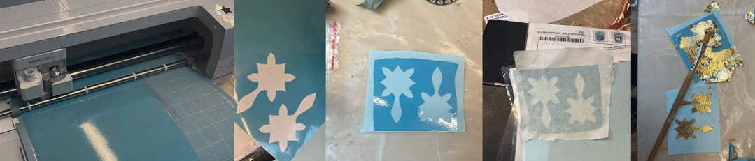
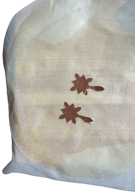
 I decided to work with sensitive tattoo. I designed this model on Adobe Illustrator. 4
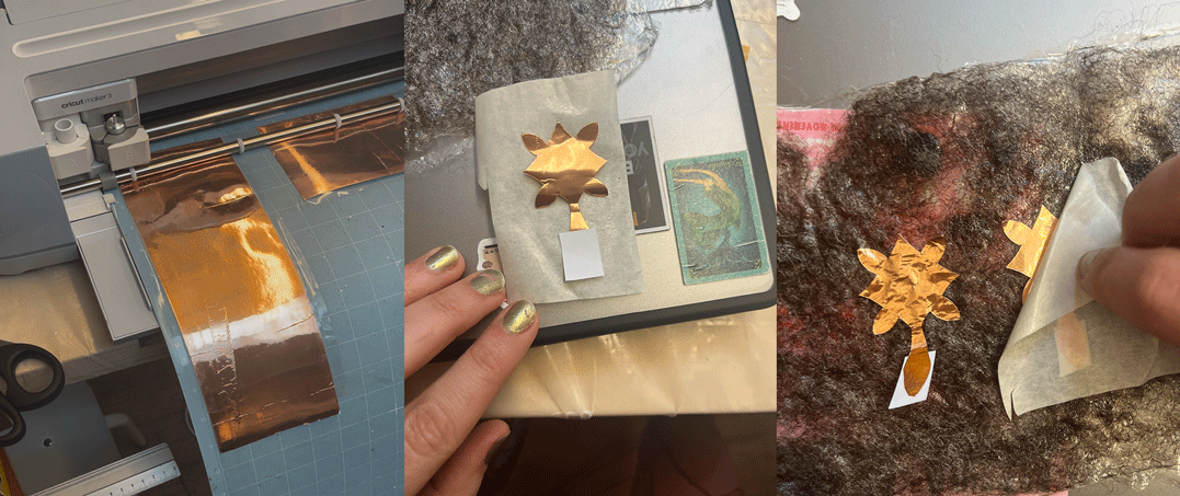
I first use the Cricut to cut the design. I connected the cutting maching via cable and I already had the softaware installed in my laptop. I saved the file ans an .svg and I uploaded it. I attached these pieces to the bioplastics I made during the Textile as Scaffold week.
I also tried making a gold leaf tattoo, but it didn’t go very well. At first, I applied the gold leaf to the wrong side of the transferable tattoo paper. When I tried a second time, the glue wouldn’t stick to the other side because it has a waterproof surface. I wasn’t able to complete this part. Perhaps I should try using a different type of glue next time.
Coding
Visuals
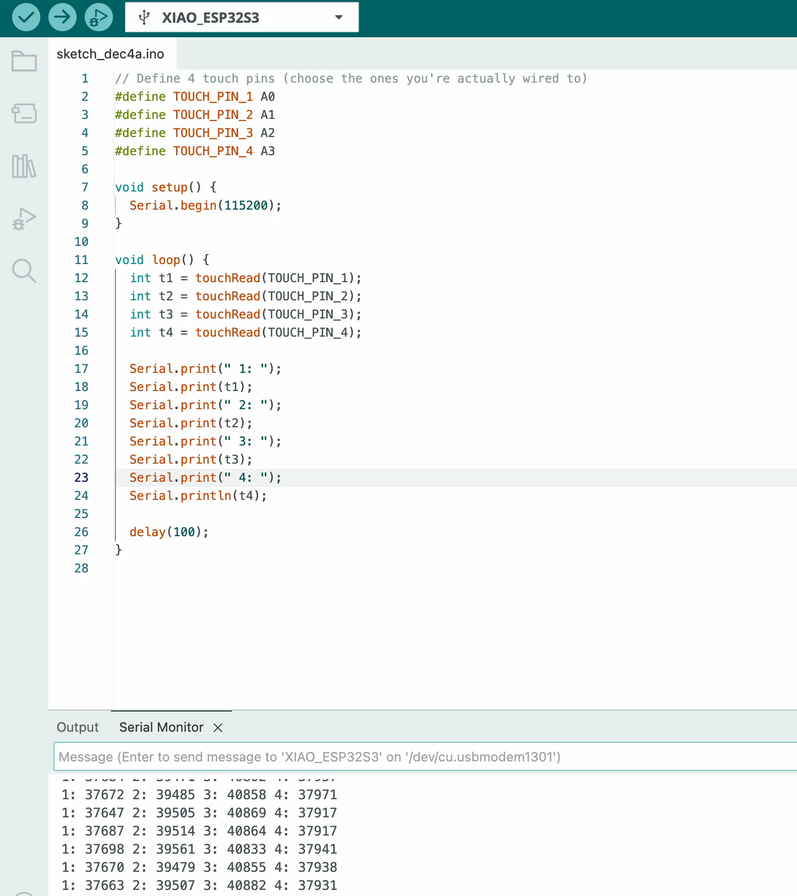
I used this code to obtain values that I couls use in processing to obtain visual (screen fading from white to black)
#define TOUCH_PIN_1 A0
#define TOUCH_PIN_2 A1
#define TOUCH_PIN_3 A2
#define TOUCH_PIN_4 A3

void setup () {

Serial.begin (115200);

}

void loop() {

int t1 = touchRead (TOUCH_PIN_1);
int t2 = touchRead (TOUCH_PIN_2);
int t3 = touchRead (TOUCH_PIN_3) ;
int t4 = touchRead (TOUCH_PIN_4) ;

Serial.print(" 1: ");
Serial.print(t1);
Serial.print(" 2: ");
Serial.print(t2);
Serial.print(" 3: ");
Serial.print(t3);
Serial.print(" 4: ");
Serial.println(t4);

delay (100);
Processing
We tried adapting the Matrix code to my 4 copper stickers. Sadly it did not work quite right.
import processing.serial.*;

Serial myPort; // The serial port
int rows = 1;
int cols = 4;
int maxNumberOfSensors = rows*cols;
float[] sensorValue = new float[maxNumberOfSensors]; // global variable for storing mapped sensor values
float[] previousValue = new float[maxNumberOfSensors]; // array of previous values
int rectSizeX = 0;
int rectSizeY = 0;
int rectY;


void setup () {
  size(1000, 1000); // set up the window to whatever size you want
  rectSizeX = width/rows;
  rectSizeY = height/cols;


  println(Serial.list()); // List all the available serial ports
  String portName = Serial.list()[3]; // set the number of your serial port!
  myPort = new Serial(this, portName, 9600);
  myPort.clear();
  myPort.bufferUntil('\n'); // don’t generate a serialEvent() until you get a newline (\n) byte
  background(255); // set inital background
  smooth(); // turn on antialiasing
  rectMode(CORNER);
}

void draw () {
  for (int i = 0; i < maxNumberOfSensors; i++) {
    //fill(sensorValue[i]);
    //rect(rectSizeX * (i%rows), rectY, rectSizeX, rectSizeY); //top left
    //if((i+1) % rows == 0) {
      //rectY += rectSizeX;
    //}
  }
  //rectY=0;
}


void serialEvent (Serial myPort) {
  String inString = myPort.readStringUntil('\n'); // get the ASCII string
  if (inString != null) { // if it’s not empty
    inString = trim(inString); // trim off any whitespace
    int incomingValues[] = int(split(inString, "\t")); // convert to an array of ints

    if (incomingValues.length <= maxNumberOfSensors && incomingValues.length > 0) {
      for (int i = 0; i < incomingValues.length; i++) {
        // map the incoming values (0 to 1023) to an appropriate gray-scale range (0-255):
        //sensorValue[i] = map(incomingValues[i], 70000, 180000, 0, 255); // stretch 5×5
        if (sensorValue[i] > 100000){
          fill(0,0,0);
        }
        else {fill(255,255,255);
        }
        rect(rectSizeX * (i%rows), rectY, rectSizeX, rectSizeY); //top left
    if((i+1) % rows == 0) {
      rectY += rectSizeX;
        //sensorValue[i] = constrain(incomingValues[i], 0, 255);
        println(sensorValue[i]); // print value to see
        println(incomingValues[i]);
      }
    }
    rectY=0;
  }
}
}
MP3
I tested the copper stickers with this code to test to obtain some values from the serial monitor
#define TOUCH1 4
#define TOUCH2 5

void setup() {
  Serial.begin(115200);
  delay(500);
  Serial.println("Touch test on GPIO4 & GPIO5...");
}

void loop() {
  int v1 = touchRead(TOUCH1);
  int v2 = touchRead(TOUCH2);

  Serial.print("Pad1: ");
  Serial.print(v1);
  Serial.print("   Pad2: ");
  Serial.println(v2);

  delay(150);
}
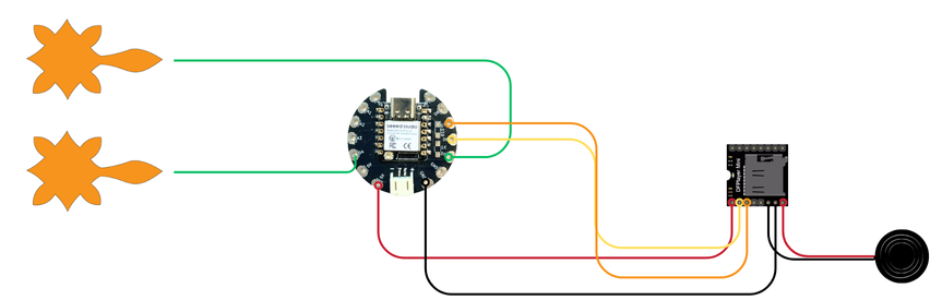
I tried connecting my sensor to an MP3, above you can find the diagram I used.
- copper stickers -> D4 - D5
- TX -> D7 (RX)
- RX -> D6 (TX)
- MP3 VCC -> 5V
- MP3 GRD -> GRD
- SPK_1 and SPK_2 -> buzzer
This is the code I used
#define TOUCH_PIN1 4
#define TOUCH_PIN2 5

int threshold1 = 200000;
int threshold2 = 100000;

HardwareSerial MP3(1);   // use UART1

void setup() {
  Serial.begin(115200);

  MP3.begin(9600, SERIAL_8N1, 6, 7);

  Serial.println("Touch + MP3 ready");
}

void loop() {
  int val1 = touchRead(TOUCH_PIN1);
  int val2 = touchRead(TOUCH_PIN2);

  Serial.print("Pad1: "); Serial.print(val1);
  Serial.print("   Pad2: "); Serial.println(val2);

  if (val1 > threshold1) {
    Serial.println("Pad 1 touched → play 0001.mp3");
    playTrack(1);
    delay(500);
  }

  if (val2 > threshold2) {
    Serial.println("Pad 2 touched → play 0002.mp3");
    playTrack(2);
    delay(500);
  }

  delay(50);
}

void playTrack(uint8_t track) {
  uint8_t cmd[10] = {0x7E,0xFF,0x06,0x03,0x00,0x00, track, 0x00, 0x00, 0xEF};
  MP3.write(cmd, 10);
}
Directly on skin
I tried attaching directly the copper tattoo on my skin but the values I was obtaining on my serial monitor where not really usable. They would onky oscillate between 39000 and 42000 being only kind of stable around 42000 when I'd touch the copper
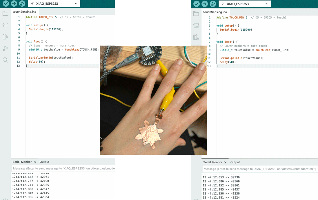
#define TOUCH_PIN 5  // D5 → GPIO5 → Touch1

void setup() {
  Serial.begin(115200);
}

void loop() {
  // Lower numbers = more touch
  uint16_t touchValue = touchRead(TOUCH_PIN);

  Serial.println(touchValue);
  delay(50);
}
Results
At the end, I attached copper tape to cling film and used it as a simple touch sensor connected to a microcontroller. The board reads changes in capacitance when I touch the copper. The printed values are sent to Processing, where they are mapped to control movement and speed of the visual dots on screen. The code was developed with the help of AI.
Arduino code
#define TOUCH_PIN_1 T1  // e.g. GPIO1 (check mapping!)
#define TOUCH_PIN_2 T2  // e.g. GPIO2

void setup() {
  Serial.begin(115200);
}

void loop() {
  uint16_t touch1 = touchRead(TOUCH_PIN_1);
  uint16_t touch2 = touchRead(TOUCH_PIN_2);

  // Send as CSV: value1,value2
  Serial.print(touch1);
  Serial.print(",");
  Serial.println(touch2);

  delay(200);
}
Processing code 5
import processing.serial.*;

Serial myPort;

// touch
float t1 = 0;
float t2 = 0;

float s1 = 0;
float s2 = 0;

// particles
int NUM = 600;
PVector[] pos = new PVector[NUM];
PVector[] vel = new PVector[NUM];

void setup() {
  size(800, 600);
  pixelDensity(1);
  background(10);

  myPort = new Serial(this, "/dev/cu.usbmodem1201", 115200);
  myPort.bufferUntil('\n');

  for (int i = 0; i < NUM; i++) {
    pos[i] = new PVector(random(width), random(height));
    vel[i] = new PVector(0, 0);
  }
}

void draw() {
  // softer fade = longer trails (brighter feel)
  noStroke();
  fill(0, 25);
  rect(0, 0, width, height);

  s1 = lerp(s1, t1, 0.1);
  s2 = lerp(s2, t2, 0.1);

  float touch1 = 1.0 - norm(s1);
  float touch2 = 1.0 - norm(s2);

  // BIGGER forces = more visible motion
  float fx = (touch1 - touch2) * 6.0;
  float fy = (touch2 - touch1) * 6.0;

  for (int i = 0; i < NUM; i++) {

    // swirling field + touch force
    float angle = noise(pos[i].x * 0.003, pos[i].y * 0.003) * TWO_PI * 3;

    vel[i].x += cos(angle) * 0.6 + fx;
    vel[i].y += sin(angle) * 0.6 + fy;

    // damping (keeps it fluid, not exploding)
    vel[i].mult(0.92);

    pos[i].add(vel[i]);

    // wrap edges
    if (pos[i].x < 0) pos[i].x = width;
    if (pos[i].x > width) pos[i].x = 0;
    if (pos[i].y < 0) pos[i].y = height;
    if (pos[i].y > height) pos[i].y = 0;

    // 🔥 BRIGHT COLOR MAPPING
    float brightness = (touch1 + touch2) * 255;

    float r = 80 + touch1 * 200;
    float g = 100 + brightness;
    float b = 200 + touch2 * 200;

    stroke(r, g, b, 180);
    strokeWeight(2); // makes it MUCH more visible

    point(pos[i].x, pos[i].y);
  }
}

// normalize touch range
float norm(float v) {
  return constrain((v - 18000) / (65000 - 18000), 0, 1);
}

// serial
void serialEvent(Serial p) {
  String data = trim(p.readStringUntil('\n'));
  if (data == null) return;

  String[] v = split(data, ',');
  if (v.length != 2) return;

  try {
    t1 = float(v[0]);
    t2 = float(v[1]);
  } catch (Exception e) {}
}