5. E-textiles
Research
E-textiles are fabrics that can do more than just cover the body — they can sense, react, and even communicate. This is possible because tiny electronics like sensors, wires, and chips are built into the fabric, but the textile stays soft and comfortable.
E-textiles is uded in smart clothes, fitness trackers, in furniture or art. Researchers are working on making them stronger, washable, and more eco-friendly.

- Screen dress by Anrealage, nytimes.com
- Flying Dresses And The Future Of Fashion, The Creators Project, youtube.com


- E-Traces by Lesia Trubat González, 2014, makezine.com
- a softwear collage, Nadia Campo Woytuk, 2020, nadiacw.github.io


- Conductive Kombucha, credits: Giulia Tomasello, 2015 – 2016, etextile-summercamp.org
- Liquid MIDI Fabric Controllers by Esteban de la Torre and Judit Karpati, weburbanist.com

- No Input Textiles In Blonduos, E-Textiles as musical interfaces, by Sophie Skach iil.is
- E-Textile Swatch Book, by Olivia Prior Olivia Prior Website
 * Sew Wearable Soft Speakers makezine.com
* Soft Speakers: Digital Embroidering of DIY Customizable, Fabric Actuators dl.acm.org
* Sew Wearable Soft Speakers makezine.com
* Soft Speakers: Digital Embroidering of DIY Customizable, Fabric Actuators dl.acm.org

- Bare Conductive Paint https://inhabitat.com/
- Drawdio adafruit.com
🧪 1. Conductive Ink / Dye
✅ Goal:
A liquid or paste that conducts electricity.
📦 Basic DIY Ingredients:
- Fine graphite powder (from soft pencils or purchased)
- Distilled water or isopropyl alcohol (70–90%)
- (Optional) Binder – to make it thicker and stick better:
PVA glue / glycerin / Sodium silicate (Na₂xSiᵧO₂ᵧ₊ₓ)
🥣 Basic Recipe:
1. Mix 2–3 teaspoons of graphite with water or alcohol to create a smooth paste.
2. Add a drop of glue or glycerin for better adhesion.
3. Stir until consistent and apply to your surface.
🧪 Result:
- Can be used to draw simple circuits, touch sensors, or flexible conductive traces.
- Typical resistance: 10–1000 Ω/cm, depending on thickness and graphite quality.
⚠️ Notes:
- Not suitable for high current.
- Conductivity decreases if the layer is too thin or cracked.
Inspiration
-
Vibrating Coil - [Claire Williams, 2016] (https://etextile-summercamp.org/swatch-exchange/vibrating-speaker/)
-
Soft tools - Stephanie Vilayphiou - GreenLab
-
Booklet & veggie moisture sensors - Kae Nagano - FabLab Kamakura
-
Felted Digital Touch Sensor - Carolina Beirao - TextileLab Amsterdam Waag FutureLab
-
Knitted samples - Alice Sowa - Icelandic Textile Center
-
Final project trajectory - Ieva Maria Dautartaite
References & Inspiration
 E-textiles Inspiration Moodboard by Carlotta Premazzi
Transductors Connections - 2009

"Physical computing and Arduino were the things that sparked my passion for multimedia and digital art during my studies at the Academy of Fine Arts — which also became the base for our working group, Transductors Connections (TC), founded with a few classmates and our professor. We dreamed of starting a fablab and continuing our experiments together.
Unfortunately, we were very few, and over time we all went our separate ways. But the passion we discovered during that period is something that still connects us — and always will."
Transductors Connections logo by Massimo Cittadini, 2009
Transductors Connections (TC) 2009
- Transductors Connections (TC) was founded in December 2009 in Carrara, in partnership with the Academy of Fine Arts, the School of New Art Technologies, and the Biennium of Net Art and Digital Cultures, as a non-profit center for documentation, research, experimentation, and artistic development. Its purpose is to promote conscious knowledge and applications of technology in fields common to contemporary arts, interaction design, and physical computing.
- TC aims to be an open reference hub, a supportive and driving network within the fields of art, science, and research connected to the open software and open hardware movements, ecological practices of Reduction, Reuse, (meta)Recycling, and exploitation of “clean” renewable energies, creative uses of electricity and electronics (both analog and digital), developments in virtual reality and augmented reality on mass-market devices, studies on innovative web and physical interfaces, and analyses of social and cultural changes driven by the pervasiveness of communication, control, and mass production technologies within a global landscape undergoing deep crisis and transformation.
- TC’s goal is to create an open space for reflection, dialogue, and exchange that allows showcasing significant experiences in the indicated fields of interest, discussing and presenting educational and extracurricular projects, sharing information and knowledge, techniques and tools, resources and contacts, and developing artistic projects and strategies focused on interpretations and transductions of original and innovative cognitive and physical realities based on “active” recycling, technological hybridization, and ecologically sustainable energies.
Figli di un utero artificiale - 2008
During this times I create an interactive installation using Arduino, leds and ultrasonic sensor.


- Circuit Sheet, Figli di un utero artificiale- 2008- Interactive Installation with Arduino and Ultrasonic Sensor. [Interactive, plug&play] by Carlotta Premazzi
- Figli di un utero artificiale 2009, Feedback Festival-Interactive Arts Festival, San Casciano Val di Pesa, Firenze, by Carlotta Premazzi
Fduua CODE
// Ultrasonic Sensor + Dual LED Example
// Uses an HC-SR04 ultrasonic sensor to measure distance and controls
// two LEDs (red and blue) based on the reading.
// Figli di un utero artificiale - 2008 code by Carlotta Premazzi

// declare pins and variables
int ledPinR = 3;       // red LED with 220Ω resistor on pin 3
int ledPinB = 6;       // blue LED with 220Ω resistor on pin 6
int valR;              // value for reading red LED state
int valB;              // value for reading blue LED state
int x = 0;
unsigned long echo = 0;
int ultraSoundSignal = 9; // ultrasound signal pin
unsigned long ultrasoundValue = 0;

// the setup function runs once when you press reset or power the board
void setup() {
  Serial.begin(9600);
  pinMode(ultraSoundSignal, INPUT);
  pinMode(ledPinR, OUTPUT);
  pinMode(ledPinB, OUTPUT);
}

// function to send and receive ultrasonic pulse
unsigned long ping() {
  pinMode(ultraSoundSignal, OUTPUT);       // switch signal pin to output
  digitalWrite(ultraSoundSignal, LOW);     // send low pulse
  delayMicroseconds(2);                    // wait for 2 microseconds
  digitalWrite(ultraSoundSignal, HIGH);    // send high pulse
  delayMicroseconds(5);                    // wait for 5 microseconds
  digitalWrite(ultraSoundSignal, LOW);     // holdoff
  pinMode(ultraSoundSignal, INPUT);        // switch signal pin to input
  digitalWrite(ultraSoundSignal, HIGH);    // turn on pullup resistor

  echo = pulseIn(ultraSoundSignal, HIGH);  // listen for echo
  ultrasoundValue = (echo / 58.138);       // convert to cm
  return ultrasoundValue;
}
Electricity & Electrical Circuits – Basics
🔌 Electricity
Electricity is the flow of electrons through a conductive material, called electric current.
⚙️ Fundamental Quantities
| Quantity | Symbol | Unit | Description |
|---|---|---|---|
| Voltage | V | Volt (V) | The “push” that moves electrons |
| Current | I | Ampere (A) | The amount of electrons flowing per second |
| Resistance | R | Ohm (Ω) | How much a material resists the flow of current |
📐 Ohm’s Law
V = I × R (Voltage = Current × Resistance)
🔋 Electrical Circuit
An electrical circuit is a closed path through which electricity can flow. It includes: - A power source (e.g., battery or Arduino 5V) - A conductor (wire, copper tape, conductive fabric) - A load (LED, motor, sensor, etc.) - (Optional) switches, resistors, or sensors
🔁 Types of Circuits
- Series: One path only. If one component fails, all stop working.
- Parallel: Multiple paths. Each component can work independently.
💡 LEDs and Polarity
LEDs are polarized components:
- Anode (+): long leg → connect to positive
- Cathode (–): short leg → connect to GND
🔸 Always use a resistor in series with an LED (e.g., 220 Ω) to avoid burning it out.
🧩 Common Components / Functions
| Component | Function Description |
|---|---|
| Battery | Supplies DC power (direct current) to a circuit |
| Resistor | Controls or limits the electrical current flow |
| LED | Emits light when current passes through it |
| Button | Opens or closes a circuit — used as input |
| Potentiometer | Varies resistance by rotation or pressure |
| Sensor | Detects changes (light, temperature, pressure…) |
| Capacitor | Stores and releases small amounts of energy |
| Transistor | Works as an electronic switch or amplifier |
Practical Tips
- ❌ Never connect an LED without a resistor
- ❌ Never connect 5V directly to GND → short circuit!
- ✅ Use a multimeter to test voltage, resistance, and continuity
- ✅ Always check the polarity of components
- ✅ For prototyping: use a breadboard or jumper wires
Tools
🔧 Multimeter
Source: Wikipedia
A multimeter is a measuring instrument used to measure multiple electrical properties, such as voltage (voltmeter), resistance (ohmmeter), and current(ammeter).
Useful for testing circuits, debugging, and verifying connections.
Jumper Wires
Flexible wires for connecting components on breadboards or linking microcontrollers to sensors/LEDs.
Types: M-M, M-F, F-F.
Used for fast prototyping without soldering.
Alligator Clip Test Leads
Wires with alligator clips at both ends for quick connections.
Good for conductive materials or temporary circuit tests.
Soldering Iron
Tool for melting solder to join electronic components.
Used for: Creating permanent connections, Repairing circuits, Electronics assembly.
⚡ Battery / Power Supply
Provides electricity to circuits.
Common voltage levels:
- 3 V – for sensors, LEDs, low-power circuits
- 5 V – standard for Arduino, logic components
- 220 V – household mains voltage (⚠️ use with caution)
💡 LED – Light Emitting Diode
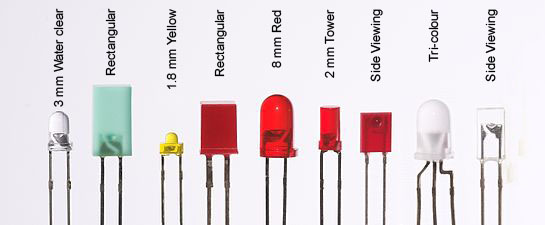

- Source: mini led
- Source: Common Anode vs Cathode – Full Guide
Source: Wikipedia
An LED (Light-Emitting Diode) is a semiconductor device that emits light when current flows through it.
- How it works:
Electrons in the semiconductor recombine with electron holes, releasing energy as photons (light). - Color of light:
Determined by the band gap of the semiconductor — different materials produce different colors. - White light:
Achieved using multiple semiconductors or a layer of light-emitting phosphor. - LED Polarity:
LEDs are polarized components, which means they only work in one direction: - Anode: (+) Long leg, Connect to positive (VCC)
- Cathode: (–) Short leg, Connect to ground (GND)
🧵 LEDs in E-Textiles


- E-Textile Led Twisted: codingireland.ie
- E-Textile Led Twisted and conductive thread by Carlotta Premazzi
Source: Beginner’s Guide to E-Textiles / Soft Circuits*
“Flatten the legs of the LED and twist one wire to create a loop large enough for a sewing needle to pass through.” Perfect for wearable electronics or soft circuit projects.
Tips for Using LEDs
- Always use a resistor (e.g. 220 Ω) in series to prevent burning the LED
- Check polarity before powering the circuit
- Use multimeters or continuity testers to identify LED orientation if unclear
- For prototyping, use a breadboard with jumper wires
Resources
- 📘 Wikipedia – Light-emitting diode
- 🧑🏫 Anode vs Cathode LED Guide
- ✂️ Beginner’s Guide to E-Textiles / Soft Circuits
Resistor

- Resistor Color Code: sparkfun.com_
- Types of Resistors mechatronicsforu.com/
Source: Wikipedia
A resistor is a passive, two-terminal electronic component that introduces electrical resistance into a circuit.
In electronic circuits, resistors are used to:
- 🔻 Reduce current flow
- 🎚️ Adjust signal levels
- ⚡ Divide voltages
- 🔋 Bias active components (like transistors)
- 📶 Terminate transmission lines
- 💡 Protect LEDs and other components
🔗 SparkFun Resistor Calculator & Guide
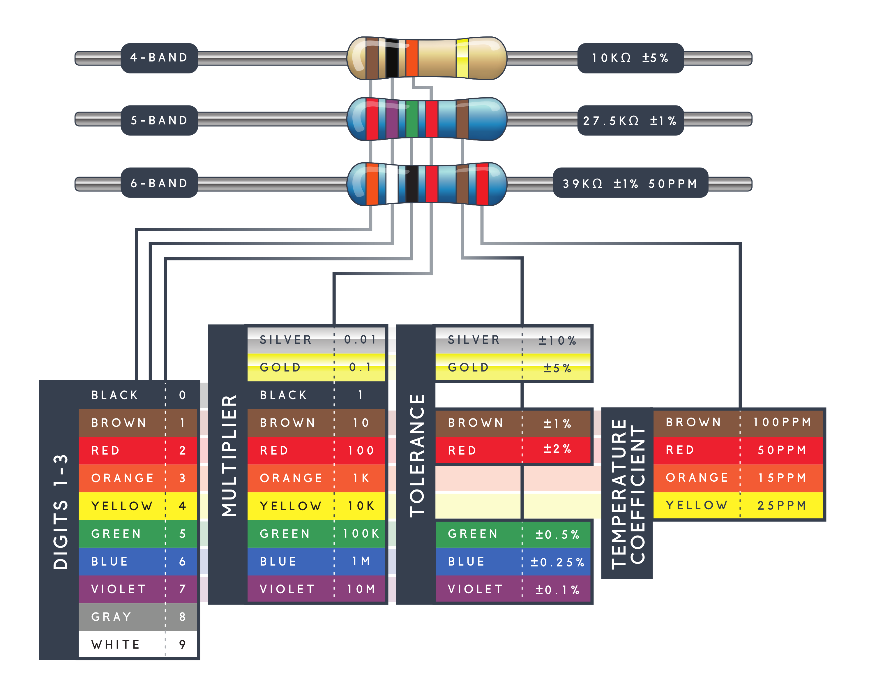
Resistor Color Code Table
Resistors are often marked with colored bands that indicate their resistance value.
| Color | Digit | Multiplier | Tolerance |
|---|---|---|---|
| Black | 0 | ×1 | — |
| Brown | 1 | ×10 | ±1% |
| Red | 2 | ×100 | ±2% |
| Orange | 3 | ×1,000 | — |
| Yellow | 4 | ×10,000 | — |
| Green | 5 | ×100,000 | ±0.5% |
| Blue | 6 | ×1,000,000 | ±0.25% |
| Violet | 7 | ×10,000,000 | ±0.1% |
| Gray | 8 | ×100,000,000 | ±0.05% |
| White | 9 | ×1,000,000,000 | — |
| Gold | — | ×0.1 | ±5% |
| Silver | — | ×0.01 | ±10% |
| None | — | — | ±20% |
💡 Example:
A resistor with bands Red – Violet – Brown – Gold means:
→ 2 (Red), 7 (Violet), ×10 (Brown) = 270 Ω, ±5% (Gold)
🌞 LDR – Light Dependent Resistor
 Photo cell CdS photoresistor Adafruit.com
A photoresistor (LDR) is a passive electronic component whose resistance decreases as the intensity of light increases.
- In the dark: resistance up to several MΩ
- In the light: resistance can drop to a few hundred Ω
Used in:
- Light-sensitive detectors
- Daylight switches
- Automatic brightness controls
💡 Flexible LED Filament
 nOOds - Flexible LED Filament, Adafruit.com
Made of dozens of LED diodes bonded together on an ultra-flexible metal backing and coated in colorful silicone.
As the LEDs are in parallel, powering them directly from 3V can draw up to 200 mA.
⚠️ It is not recommended to drive them in voltage mode.
Use a current-limiting resistor to allow max 50 mA.
Treat them as:
- If = 50 mA
- Vf = 3 V
E-Textile Conductive Materials
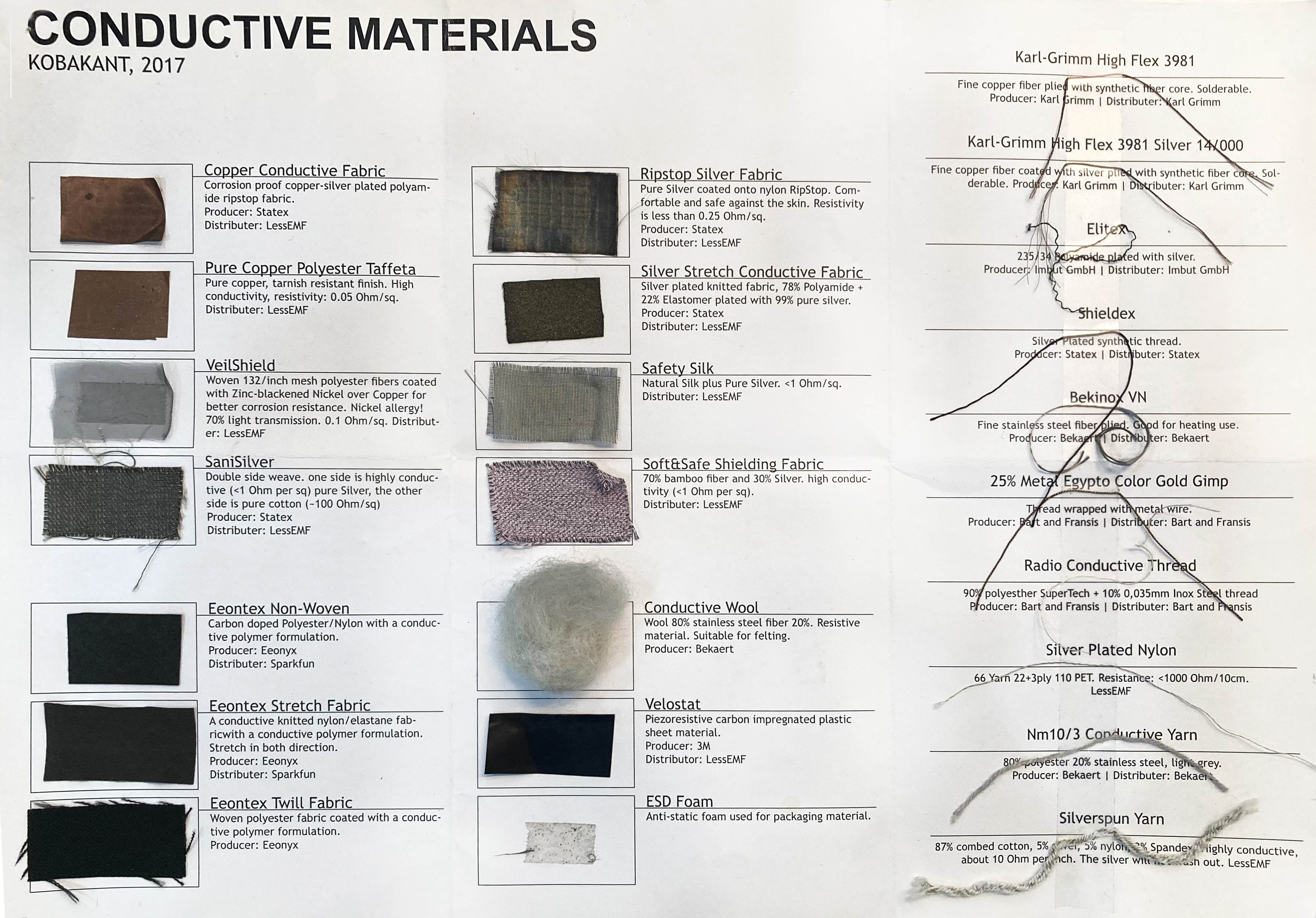 Source kobakant
🧵 Stainless Thin Conductive Thread
 Adafruit.com
- Material: 316L stainless steel
- Structure: 2-ply, thicker than cotton/polyester thread
- Resistivity: ~16 ohms/foot
- Usage: Suitable for powering LEDs and components under ~50 mA
📏 Pressure-Sensitive Conductive Sheet (Velostat / Linqstat)
 Velostat (Linqstat), Adafruit.com
From Wikipedia
A piezoresistive polymer foil (polyolefins + carbon black) that becomes more conductive when pressed or flexed — resistance drops from ~9 kΩ to ~1 kΩ.
Used for:
- DIY pressure or flex sensors
- Light-up wearables
- Voltage divider circuits to detect force
🔘 Tactile Switch Buttons
 Adafruit.com
- 12mm square, 6mm tall
- Medium-sized momentary push buttons
- Provide tactile click
- Used as digital input for user interaction
📡 Ultrasonic Distance Sensor – HC-SR04
 Source: Adafruit
📘 Overview
The HC-SR04 is an ultrasonic distance sensor that measures distance using sound waves. It operates in a similar way to how bats and dolphins navigate: by emitting a sound and detecting its echo.
"Ultrasonic" refers to sound waves above the range of human hearing — typically above 20 kHz.
🔍 How It Works
- The transmitter emits a high-frequency ultrasonic pulse (≈40 kHz).
- The sound wave travels through the air.
- When it hits an object, it bounces back toward the sensor.
- The receiver detects the reflected wave.
- The Arduino measures the time taken for the sound to return.
- Using that time and the speed of sound, it calculates the distance.
🔌 Pinout
The HC-SR04 has 4 pins:
| Pin | Description |
|---|---|
| VCC | Connect to 5V (or 3.3V with logic level shifting) |
| GND | Ground |
| Trig | Trigger pin – Sends ultrasonic pulse |
| Echo | Echo pin – Listens for reflected pulse |
Use any digital pins on the Arduino for Trig and Echo.
⚙️ Technical Specifications
| Specification | Value |
|---|---|
| Operating Voltage | 5V DC |
| Operating Current | 15 mA |
| Operating Frequency | 40 KHz |
| Minimum Range | 2 cm (≈ 1 inch) |
| Maximum Range | 400 cm (≈ 13 feet) |
| Accuracy | ±3 mm |
| Measuring Angle | < 15° |
| Dimensions | 45 × 20 × 15 mm |
🧪 Learn More
🔳 Breadboard


- Breadboard exterior and interior Adafruit.com
Source: Wikipedia
A breadboard is a construction base used to build semi-permanent prototypes of electronic circuits.
Unlike perfboards or stripboards, breadboards: - 🧷 Do not require soldering - 🔁 Are reusable - 🧪 Allow quick changes and experimentation without damaging components
For these reasons, breadboards are widely used in: - 👩🎓 Education - 👨🔬 Electronics prototyping - 🧪 Arduino and physical computing projects
🔗 Learn with Adafruit: Breadboards for Beginners
🔧 Arduino Uno Rev3
📚 Overview


- Arduino Uno Rev3, Arduino Uno Rev3 Pinout Diagram arduino.cc
The Arduino Uno Rev3 is one of the most popular boards in the Arduino ecosystem. Developed by Arduino, an open-source hardware and software platform, it is widely used for creating interactive electronic projects.
Arduino is a company, project, and global user community that designs and manufactures open-source single-board microcontrollers and kits.
🧩 Hardware licensed under CC BY-SA, 💻 Software licensed under GNU LGPL or GPL, allowing anyone to manufacture boards and distribute software
Boards include digital and analog I/O pins for connection to: Expansion boards (shields), Breadboards (for prototyping),Other electronic circuits.
They support serial communication, often via USB, which is also used for uploading code.
Arduino programs are written in C/C++ (Embedded C) using a standard API known as the Arduino Programming Language, based on Processing, and written using the Arduino IDE or Arduino CLI (Go-based).
⚙️ 🔩 Arduino Uno (R3) – Key Features
- Microcontroller: ATmega328P
- 14 Digital I/O Pins
↪ 6 can be used as PWM outputs - 6 Analog Input Pins
- 16 MHz Ceramic Resonator (CSTCE16M0V53-R0)
- USB connection
- Power jack
- ICSP header
- Reset button
⚙️ Technical Specifications
| Specification | Value |
|---|---|
| Microcontroller | ATmega328P |
| Operating Voltage | 5V |
| Input Voltage (recommended) | 7–12V |
| Input Voltage (limit) | 6–20V |
| Digital I/O Pins | 14 (6 with PWM output) |
| PWM Digital I/O Pins | 6 |
| Analog Input Pins | 6 |
| DC Current per I/O Pin | 20 mA |
| DC Current for 3.3V Pin | 50 mA |
| Flash Memory | 32 KB (0.5 KB used by bootloader) |
| SRAM | 2 KB |
| EEPROM | 1 KB |
| Clock Speed | 16 MHz |
| LED_BUILTIN | Pin 13 |
| Dimensions | 68.6 mm × 53.4 mm |
| Weight | 25 g |
Arduino Simulators & Tools
Explore and experiment with Arduino circuits directly in your browser using these powerful simulators:
- 🔗 circuito.io
An interactive circuit builder that helps you plan and simulate Arduino projects with code suggestions. - 🔗 Tinkercad Circuits
Beginner-friendly simulator by Autodesk. Ideal for prototyping and learning Arduino and electronics. - 🔗 Wokwi
Advanced online Arduino simulator that supports a wide range of boards, sensors, and real-time code simulation. - 🔗 Fritzingused here
An open-source tool for designing circuits, creating schematics, and generating PCB layouts. Great for documentation and real-world builds.
References
_ Arduino Uno - Arduino Uno - Official Product Page * Wikipedia – ArduinoWikipedia – Arduino * Datasheet ATmega328 * SparkFun Electronics * The Making of Arduino by David Kushner, 2011
💻 Arduino IDE
Source Wikipedia
The Arduino Integrated Development Environment (IDE) is a free, cross-platform tool (Windows, macOS, Linux) used to write, compile, and upload code to Arduino boards.
- Based on Processing IDE (Java) and Wiring API
- Supports C/C++ with Arduino-specific structure
- Includes:
- Code editor with syntax highlighting, auto-indentation
- One-click compile and upload
- Console, toolbar, and menus
- Uses avrdude to upload HEX files to the board
- Includes GNU toolchain and Wiring libraries
- Originally for AVR microcontrollers, now supports platforms like ESP32, STM32, and TI MSP430
🔓 Open-source, licensed under GNU GPL v2
Process and workflow

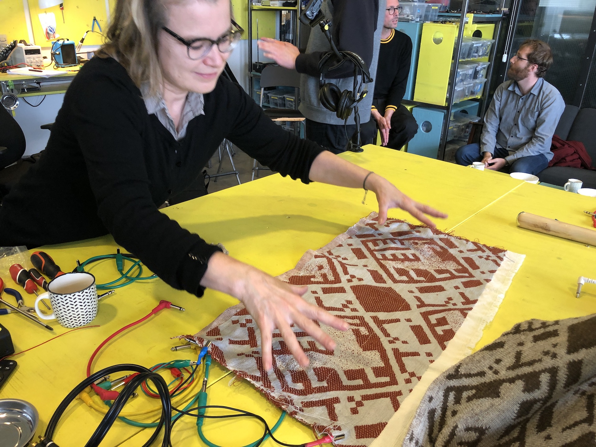
Conductive materials and test by Carlotta Premazzi
Various conductive materials were tested — some performed better than others, depending on their chemical composition and form.
TIPS
- If two conductive points are closer together and the connection path is more direct or interlocked, the conductivity improves.
Swatches
In the context of e-textiles, a swatch is: A small fabric sample that demonstrates a specific electronic behavior or technique, a mini textile prototype.
DIGITAL SOFT BUTTON
A digital soft button is a fabric or flexible switch that only has two states: ON (pressed)/OFF (not pressed)
Clip Clap Button/Zip

Soft Digital Sensor Button by Carlotta Premazzi

Clip Clap Button, Soft Digital Button by Carlotta Premazzi
tools
Jeans, felt, conductive thread, metal buttons/zip.
The Clip Clap Button closes the circuit when two conductive parts touch, like snapping a button or closing a zipper. It acts as a simple on/off switch.
ZIP TIPS
- A good example of a button — but be aware that you may have trouble opening and closing the zipper due to the thickness of the thread.
ANALOGIC SOFT BUTTON
An analog soft button responds with a range of values, depending on how much pressure is applied. It can sense soft press, medium press, hard press, etc.
This is useful for more precise input, like controlling brightness, volume, or movement.
Velostat Heart Pillow (change RGB/Heart)
tools
Jeans, felt, conductive foil, conductive fabric tape, velostat, rgb led.
The current flows through two aluminum sheets arranged in a sandwich structure, with Velostat placed in between. The Velostat changes its resistance in response to pressure, altering the overall conductivity of the setup.

 Connecting hearts, Soft Analog by Carlotta Premazzi
- Velostat Pillow, Soft Analog Button by Carlotta Premazzi
- Velostat Pillow, Soft Analog Button/Pressure Sensor. Analog Serial Reading from Arduino, Serial Monitor and Serial Plotter by Carlotta Premazzi
Velostat Pressure Sensor CODE
// Velostat Pressure Sensor - Basic Reading
// 16-10-2025 by Carlotta Premazzi, Fabricademy
// file: velostat_basic.ino
//
// This sketch reads analog values from a Velostat pressure sensor,
// useful for detecting **touch, pressure, or bending**.
//
// Setup:
// - The Velostat is wired as a **voltage divider**:
//     - One side → **+5V**
//     - Other side → a **resistor (e.g. 10kΩ)** to **GND**
//     - Middle point (between Velostat and resistor) → **A0**
//
// Use the **Serial Monitor** to observe how the value changes when you press the sensor.

int sensorPin = A0;    // analog input pin connected to Velostat
int sensorValue = 0;   // variable to store the reading

void setup() {
  Serial.begin(9600);  // start serial communication at 9600 baud
}

void loop() {
  sensorValue = analogRead(sensorPin);  // read sensor value
  Serial.println(sensorValue);          // print for calibration
  delay(250);                           // small delay between readings
}
Sketches

Blink Circuit and Schematics Arduino.cc
Blink – Arduino LED Example
/*
Blink
Turn an LED on for one second, then off for one second, repeatedly.
Modified 8 May 2014, by Scott Fitzgerald
Modified 2 Sep 2016, by Arturo Guadalupi
Modified 8 Sep 2016 by Colby Newman

This example code is in the public domain.
https://www.arduino.cc/en/Tutorial/BuiltInExamples/Blink
*/

// the setup function runs once when you press reset or power the board
void setup() {
  // initialize digital pin LED_BUILTIN as an output
  pinMode(LED_BUILTIN, OUTPUT);
}

// the loop function runs over and over again forever
void loop() {
  digitalWrite(LED_BUILTIN, HIGH);  // turn the LED on (HIGH is the voltage level)
  delay(1000);                       // wait for a second
  digitalWrite(LED_BUILTIN, LOW);    // turn the LED off by making the voltage LOW
  delay(1000);                       // wait for a second
}
Blinking-automatic cycles Leds
"RGB LED Alternating Blink (Green/Red)"
 Circuit by Carlotta Premazzi made with Wokwi
RGB LED Alternating Blink CODE
/*
  RGB LED Alternating Blink (Green/Red)
  15-10-2025 by Carlotta Premazzi, Fabricademy
  file: sketch_oct15_2_LED_Alternating_Blink.ino

  This sketch blinks two LEDs connected to digital pins:
  - Pin 13 → Green LED (on for 1 second)
  - Pin 9  → Red LED (on for 250 ms)

  How it works:
  - The green LED turns on while the red one is off, then they alternate.
  - Useful for testing LED connections, timing, and digital outputs.

  Required components:
  - Two LEDs (green and red)
  - Two resistors (e.g. 220Ω)
  - Arduino Uno or compatible board

  Great for checking if digital pins are working properly
  and for adapting to visual feedback or simple outputs.
*/

void setup() {
  // put your setup code here, to run once:
  // 13 is GREEN, 9 is RED
  pinMode(13, OUTPUT);
  pinMode(9, OUTPUT);
}

void loop() {
  // put your main code here, to run repeatedly:
  digitalWrite(13, HIGH);
  digitalWrite(9, LOW);
  delay(1000);

  digitalWrite(13, LOW);
  digitalWrite(9, HIGH);
  delay(250);

  delay(20);
}
RGB LED Automatic Rainbow Cycle
CODE – RGB LED Automatic Rainbow Cycle
/*
  📁 RGB LED automatic rainbow cycle using HSV to RGB conversion
  23-10-2025 by Carlotta Premazzi, Fabricademy
  file: sketch_oct16_automatic_rainbow_cycle.ino

  🔧 Description:
  This sketch smoothly cycles an RGB LED through the full color spectrum
  by converting a hue angle (HSV model) to RGB values.

  🧠 How it works:
  - A float variable `hue` increases over time from 0 to 360°.
  - `hsvToRgb()` converts hue to RGB values.
  - RGB values are applied to the LED via `analogWrite()`.
  - Once hue reaches 360°, it wraps back to 0.
  - Delay controls speed of the transition.

  🧩 Required components:
  - 1 × Common cathode RGB LED (or equivalent)
  - 3 × 220Ω resistors (for R, G, B pins)
  - Arduino Uno or compatible board
  - Breadboard + jumper wires

  💡 Notes:
  - Pins 9, 10, 11 are used for PWM output (Red, Green, Blue).
  - Adjust `delay(20)` to make the rainbow faster or slower.
  - Compatible with standard HSV → RGB conversion logic.

  🔗 Based on or inspired by:
  Standard HSV to RGB conversion formulas, Arduino analogWrite, color theory.

  Created for learning, experimentation or prototyping.
*/

const int ledR = 9;     // Red pin
const int ledG = 10;    // Green pin
const int ledB = 11;    // Blue pin

float hue = 0.0;        // Hue angle (0–360)

void setup() {
  pinMode(ledR, OUTPUT);
  pinMode(ledG, OUTPUT);
  pinMode(ledB, OUTPUT);
}

void loop() {
  int r, g, b;

  // Convert HSV hue to RGB
  hsvToRgb(hue, 1.0, 1.0, &r, &g, &b);
  setRGB(r, g, b);

  // Increment hue
  hue += 1.0;
  if (hue > 360.0) hue = 0.0;

  delay(20);  // Adjust speed of color transition
}

void setRGB(int r, int g, int b) {
  analogWrite(ledR, r);
  analogWrite(ledG, g);
  analogWrite(ledB, b);
}

// Converts HSV (Hue, Saturation, Value) to RGB
void hsvToRgb(float h, float s, float v, int* r, int* g, int* b) {
  float c = v * s;
  float x = c * (1 - abs(fmod(h / 60.0, 2) - 1));
  float m = v - c;

  float r1, g1, b1;

  if (h < 60) {
    r1 = c; g1 = x; b1 = 0;
  } else if (h < 120) {
    r1 = x; g1 = c; b1 = 0;
  } else if (h < 180) {
    r1 = 0; g1 = c; b1 = x;
  } else if (h < 240) {
    r1 = 0; g1 = x; b1 = c;
  } else if (h < 300) {
    r1 = x; g1 = 0; b1 = c;
  } else {
    r1 = c; g1 = 0; b1 = x;
  }

  *r = (r1 + m) * 255;
  *g = (g1 + m) * 255;
  *b = (b1 + m) * 255;
}
Velostat
Velostat Pressure Sensor – RGB Color Change"
CODE – Velostat Pressure Sensor – RGB Color Change
/*
  💡 Velostat Pressure Sensor – RGB Color Change
  16-10-2025 by Carlotta Premazzi, Fabricademy
  file: sketch_oct16_velostat_code_change_RGB.ino

  🔧 Description:
  This sketch maps pressure from a Velostat sensor to a full rainbow of colors.
  When not pressed, the LED shows red. As pressure increases, it shifts through
  orange, yellow, green, blue, and ends at violet/pink – without cycling back to red.

  🧠 How it works:
  - The Velostat sensor changes resistance with pressure.
  - The analog input reads this change as values between ~300–880.
  - These values are mapped to hue (0–300) to cover most of the visible spectrum.
  - The hue is converted to RGB values and written to an RGB LED.

  🧩 Required components:
  - 1 × RGB LED (common cathode)
  - 3 × 220Ω resistors
  - 1 × Velostat pressure sensor
  - 1 × Arduino Uno (or compatible board)
  - Breadboard + jumper wires

  💡 Notes:
  - Calibrate the `map()` range depending on your sensor readings.
  - Works best with a soft Velostat pad and stable finger pressure.
  - Adjust `delay(30)` for smoother or faster transitions.

  🔗 Based on or inspired by:
  HSV to RGB conversion formulas, pressure sensor experiments, Arduino analogWrite.
*/

const int ledR = 9;         // Red pin of the RGB LED
const int ledG = 10;        // Green pin of the RGB LED
const int ledB = 11;        // Blue pin of the RGB LED

const int sensorPin = A0;   // Analog input connected to Velostat pressure sensor
int sensorValue = 0;        // Stores the current pressure reading

void setup() {
  pinMode(ledR, OUTPUT);
  pinMode(ledG, OUTPUT);
  pinMode(ledB, OUTPUT);

  Serial.begin(9600);       // Enable Serial Monitor for debugging sensor values
}

void loop() {
  sensorValue = analogRead(sensorPin); // Read the pressure sensor value
  Serial.println(sensorValue);         // Print it to the Serial Monitor for calibration

  // Map pressure from 880 (no pressure) to 300 (strong pressure)
  // to hue values from 0 (red) to 300 (violet), avoiding looping back to red
  float hue = map(sensorValue, 880, 300, 0, 300);
  hue = constrain(hue, 0, 300);

  int r, g, b;
  hsvToRgb(hue, 1.0, 1.0, &r, &g, &b);
  setRGB(r, g, b);

  delay(30);
}

void setRGB(int r, int g, int b) {
  analogWrite(ledR, r);
  analogWrite(ledG, g);
  analogWrite(ledB, b);
}

void hsvToRgb(float h, float s, float v, int* r, int* g, int* b) {
  float c = v * s;
  float x = c * (1 - abs(fmod(h / 60.0, 2) - 1));
  float m = v - c;

  float r1, g1, b1;

  if (h < 60) {
    r1 = c; g1 = x; b1 = 0;
  } else if (h < 120) {
    r1 = x; g1 = c; b1 = 0;
  } else if (h < 180) {
    r1 = 0; g1 = c; b1 = x;
  } else if (h < 240) {
    r1 = 0; g1 = x; b1 = c;
  } else {
    r1 = x; g1 = 0; b1 = c;
  }

  *r = (r1 + m) * 255;
  *g = (g1 + m) * 255;
  *b = (b1 + m) * 255;
}
Velostat Pressure → RGB Spectrum"
 Circuit by Carlotta Premazzi made with Wokwi
CODE – Velostat Pressure → RGB Spectrum
/*
  💡 Velostat Pressure → RGB Spectrum
  16-10-2025 by Carlotta Premazzi, Fabricademy
  file: sketch_oct16_velostat_code_change_rainbow_RGB.ino

  🔧 Description:
  This sketch maps pressure from a Velostat sensor to a full rainbow of colors.
  When not pressed, the LED shows red. As pressure increases, it shifts through
  orange, yellow, green, blue, and ends at violet/pink — without looping back to red.

  🧠 How it works:
  - The Velostat sensor changes resistance depending on applied pressure.
  - The analog reading (0–1023) is mapped to a hue range (0–300).
  - The hue is converted to RGB values via `hsvToRgb()` and sent to the LED.
  - The LED smoothly transitions through the color spectrum as pressure changes.

  🧩 Required components:
  - 1 × RGB LED (common cathode)
  - 3 × 220Ω resistors
  - 1 × Velostat pressure sensor
  - 1 × Arduino Uno or compatible board
  - Breadboard + jumper wires

  💡 Notes:
  - Adjust the `map()` input range (`930 → 300`) to match your sensor calibration.
  - Works best with soft Velostat sheets and gradual pressure.
  - You can modify `delay(30)` to control transition smoothness.

  🔗 Based on or inspired by:
  Arduino analogRead(), analogWrite(), and HSV color conversion logic.
*/

const int ledR = 9;         // Red pin of the RGB LED
const int ledG = 10;        // Green pin of the RGB LED
const int ledB = 11;        // Blue pin of the RGB LED

const int sensorPin = A0;   // Analog input connected to Velostat pressure sensor
int sensorValue = 0;        // Stores the current pressure reading

void setup() {
  pinMode(ledR, OUTPUT);
  pinMode(ledG, OUTPUT);
  pinMode(ledB, OUTPUT);

  Serial.begin(9600);       // For sensor value debugging
}

void loop() {
  sensorValue = analogRead(sensorPin);  // Read sensor (0–1023)
  Serial.println(sensorValue);          // Monitor value for calibration

  // Map pressure from 930 (no pressure) to 300 (strong pressure)
  // to hue values from 0 (red) to 300 (violet), avoiding loop to red
  float hue = map(sensorValue, 930, 300, 0, 300);
  hue = constrain(hue, 0, 300);        // Ensure hue stays in range

  int r, g, b;
  hsvToRgb(hue, 1.0, 1.0, &r, &g, &b); // Convert HSV to RGB
  setRGB(r, g, b);                     // Update LED color

  delay(30); // Smooth transition
}

// Set RGB LED values
void setRGB(int r, int g, int b) {
  analogWrite(ledR, r);
  analogWrite(ledG, g);
  analogWrite(ledB, b);
}

// Convert HSV (hue: 0–360, saturation: 0–1, value: 0–1) to RGB (0–255)
void hsvToRgb(float h, float s, float v, int* r, int* g, int* b) {
  float c = v * s;
  float x = c * (1 - abs(fmod(h / 60.0, 2) - 1));
  float m = v - c;

  float r1, g1, b1;

  if (h < 60) {
    r1 = c; g1 = x; b1 = 0;
  } else if (h < 120) {
    r1 = x; g1 = c; b1 = 0;
  } else if (h < 180) {
    r1 = 0; g1 = c; b1 = x;
  } else if (h < 240) {
    r1 = 0; g1 = x; b1 = c;
  } else if (h < 300) {
    r1 = x; g1 = 0; b1 = c;
  } else {
    r1 = c; g1 = 0; b1 = x;
  }

  *r = (r1 + m) * 255;
  *g = (g1 + m) * 255;
  *b = (b1 + m) * 255;
}
Ultrasonic Sensor HC-SR04
Ultrasonic Sensor HC-SR04 – Measure Distance"
CODE – Ultrasonic Sensor HC-SR04 – Measure Distance
/*
  💡 Ultrasonic Sensor HC-SR04 – Measure Distance
  17-10-2025 by Carlotta Premazzi, Fabricademy
  file: sketch_oct17_Ultrasonic_sensor_measure_distance.ino

  🔧 Description:
  This sketch uses an HC-SR04 ultrasonic sensor to measure
  distance in cm and inches and outputs the values to the Serial Monitor.

  🧠 How it works:
  - Trigger an ultrasonic pulse on the sensor.
  - Measure the duration of the echo pulse.
  - Convert the echo duration to distance in centimeters and inches.
  - Print the results to Serial Monitor.

  🧩 Required components:
  - 1 × HC-SR04 ultrasonic sensor
  - Arduino Uno or compatible board
  - Jumper wires + breadboard

  💡 Notes:
  - Short delay ensures reliable measurements.
  - Can be used as a base for projects controlling LEDs or motors based on distance.

  🔗 Based on or inspired by:
  Rui Santos, https://randomnerdtutorials.com

  Created for learning, experimentation or prototyping.
*/

int trigPin = 12;    // Trigger
int echoPin = 13;    // Echo
long duration, cm, inches;

void setup() {
  Serial.begin(9600);       // Start Serial communication
  pinMode(trigPin, OUTPUT); // Define pins
  pinMode(echoPin, INPUT);
}

void loop() {
  // Trigger sensor with a clean HIGH pulse
  digitalWrite(trigPin, LOW);
  delayMicroseconds(5);
  digitalWrite(trigPin, HIGH);
  delayMicroseconds(10);
  digitalWrite(trigPin, LOW);

  // Read echo duration
  duration = pulseIn(echoPin, HIGH);

  // Convert duration to distance
  cm = (duration / 2) / 29.1;
  inches = (duration / 2) / 74;

  Serial.print(inches);
  Serial.print(" in, ");
  Serial.print(cm);
  Serial.print(" cm");
  Serial.println();

  delay(250);
}
HC-SR04 + RGB LED Rainbow Distance Color Map"
 Circuit by Carlotta Premazzi made with Wokwi
CODE – HC-SR04 + RGB LED Rainbow Distance Color Map
/*
  💡 HC-SR04 + RGB LED Rainbow Distance Color Map
  17-10-2025 by Carlotta Premazzi, Fabricademy
  file: sketch_oct17b_Ultrasonic_sensor_distance_color_map.ino

  🔧 Description:
  This sketch uses an HC-SR04 ultrasonic sensor to measure distance
  and maps it to a rainbow color on an RGB LED.
  Closer distance → red/orange, farther → green/blue/violet.

  🧠 How it works:
  - Trigger an ultrasonic pulse and measure the echo duration.
  - Convert echo time to distance in cm.
  - Map distance to hue (0–300°) to avoid looping back to red.
  - Convert HSV hue to RGB and output to LED using PWM.

  🧩 Required components:
  - 1 × HC-SR04 ultrasonic sensor
  - 1 × Common cathode RGB LED
  - 3 × 220Ω resistors (R, G, B)
  - Arduino Uno or compatible board
  - Jumper wires + breadboard

  💡 Notes:
  - Adjust mapping values for different distance ranges or LED types.
  - Delay of 100 ms ensures smooth color updates.
  - Serial Monitor can be used for debugging and calibration.

  🔗 Based on or inspired by:
  HSV to RGB conversion, Arduino PWM control, RGB LED tutorials.

  Created for learning, experimentation or prototyping.
*/

const int trigPin = 12;  // Trigger pin del sensore
const int echoPin = 13;  // Echo pin del sensore

const int ledR = 9;
const int ledG = 10;
const int ledB = 11;

long duration;
int distanceCM;

void setup() {
  pinMode(trigPin, OUTPUT);
  pinMode(echoPin, INPUT);

  pinMode(ledR, OUTPUT);
  pinMode(ledG, OUTPUT);
  pinMode(ledB, OUTPUT);

  Serial.begin(9600);
}

void loop() {
  // Trigger pulse per il sensore
  digitalWrite(trigPin, LOW);
  delayMicroseconds(5);
  digitalWrite(trigPin, HIGH);
  delayMicroseconds(10);
  digitalWrite(trigPin, LOW);

  // Lettura tempo del ritorno dell'eco
  duration = pulseIn(echoPin, HIGH);
  distanceCM = duration * 0.0343 / 2;

  Serial.print("Distance: ");
  Serial.print(distanceCM);
  Serial.println(" cm");

  // Mappa la distanza in una hue (0–300° per evitare loop sul rosso)
  float hue = map(distanceCM, 5, 50, 0, 300);
  hue = constrain(hue, 0, 300);

  int r, g, b;
  hsvToRgb(hue, 1.0, 1.0, &r, &g, &b);
  setRGB(r, g, b);

  delay(100);
}

void setRGB(int r, int g, int b) {
  analogWrite(ledR, r);
  analogWrite(ledG, g);
  analogWrite(ledB, b);
}

// Conversione HSV → RGB
void hsvToRgb(float h, float s, float v, int* r, int* g, int* b) {
  float c = v * s;
  float x = c * (1 - abs(fmod(h / 60.0, 2) - 1));
  float m = v - c;

  float r1, g1, b1;

  if (h < 60) {
    r1 = c; g1 = x; b1 = 0;
  } else if (h < 120) {
    r1 = x; g1 = c; b1 = 0;
  } else if (h < 180) {
    r1 = 0; g1 = c; b1 = x;
  } else if (h < 240) {
    r1 = 0; g1 = x; b1 = c;
  } else {
    r1 = x; g1 = 0; b1 = c;
  }

  *r = (r1 + m) * 255;
  *g = (g1 + m) * 255;
  *b = (b1 + m) * 255;
}
LED Filament Distance Relative Light"
CODE – LED Filament Distance Relative Light
/*
  💡 LED Filament – Distance Relative Light
  17-10-2025 by Carlotta Premazzi, Fabricademy
  file: sketch_oct17d_LED_Filament_Distance_Relative_Light.ino

  🔧 Description:
  This sketch uses an ultrasonic sensor (HC-SR04) to measure distance
  and adjusts the brightness of a LED filament accordingly.
  When closer, the LED is brighter; when farther, it dims smoothly.

  🧠 How it works:
  - Trigger an ultrasonic pulse using HC-SR04 sensor.
  - Measure the echo duration to calculate distance.
  - Map distance (5–50 cm) to LED brightness (255–50).
  - Apply PWM output to LED filament for smooth brightness change.

  🧩 Required components:
  - 1 × HC-SR04 ultrasonic sensor
  - 1 × LED filament
  - 1 × Arduino Uno (or compatible board)
  - Jumper wires + resistors (if needed)

  💡 Notes:
  - Adjust the mapping values for different sensor ranges or LED types.
  - Works best for distances within ~5–50 cm.
  - Serial Monitor can be used to debug or calibrate distances.

  🔗 Based on or inspired by:
  Arduino HC-SR04 tutorials, PWM brightness control examples.

  Created for learning, experimentation or prototyping.
*/

const int trigPin = 12;
const int echoPin = 13;
const int ledPin = 9;     // PWM pin connected to LED filament

long duration;
int distanceCM;

void setup() {
  pinMode(trigPin, OUTPUT);
  pinMode(echoPin, INPUT);
  pinMode(ledPin, OUTPUT);

  Serial.begin(9600);       // For distance debugging
}

void loop() {
  // Trigger ultrasonic pulse
  digitalWrite(trigPin, LOW);
  delayMicroseconds(5);
  digitalWrite(trigPin, HIGH);
  delayMicroseconds(10);
  digitalWrite(trigPin, LOW);

  // Read echo duration
  duration = pulseIn(echoPin, HIGH);
  distanceCM = duration * 0.0343 / 2;

  Serial.print("Distanza: ");
  Serial.print(distanceCM);
  Serial.println(" cm");

  // Map distance (5–50 cm) to LED brightness (255–50)
  int brightness = map(distanceCM, 5, 50, 255, 50);
  brightness = constrain(brightness, 0, 255);

  analogWrite(ledPin, brightness);

  delay(100);
}
MAX30102 Heart Rate and Oxygen Sensor
MAX30102 Heart Rate and Oxygen Sensor + Arduino
The MAX30102 is a compact optical sensor used to measure heart rate and blood oxygen saturation (SpO₂). It's widely used in wearables, health monitoring devices, and interactive biofeedback projects.
It works using two LEDs—one red (~660 nm) and one infrared (~880 nm)—that shine light through skin tissue (typically a fingertip or earlobe). A photodiode detects how much light is absorbed by the blood, which changes with heartbeats and oxygen levels.

- MAX30102 Heart Rate and Oxygen Sensor temperosystems.com
- Schematics MAX30102 Heart Rate and Oxygen Sensor+Arduino arduino.cc
🔗 References / Guides
🧩 Connecting to Arduino
- VCC (Voltage Common Collector) → 3.3 V or 5 V
- GND (Ground) → GND
- SCL (Serial Clock Line) → A5 (Arduino Uno)
- SDA (Serial Data Line) → A4 (Arduino Uno)
📦 Libraries to use: Adafruit MAX3010x Library, SparkFun MAX3010x Library
CODE – MAX30105 Heart Rate Sensor
/*
  📁 MAX30105 Heart Rate Sensor Reading
  21-10-2025 by Carlotta Premazzi, Fabricademy
  file: sketch_oct21b_MAX30102.ino

  🔧 Description:
  This sketch reads the heart rate using a MAX30105 pulse oximeter sensor.
  It calculates beats per minute (BPM) and a short-term moving average.

  🧠 How it works:
  - MAX30105 sensor measures IR light reflected from the finger.
  - `checkForBeat()` detects heart beats.
  - BPM is calculated from the time between beats.
  - Short-term average of BPM is computed over 4 readings.
  - Serial monitor displays current IR value, BPM, and average BPM.

  🧩 Required components:
  - MAX30105 sensor module
  - Arduino Uno or compatible board
  - Jumper wires
  - Optional: breadboard

  💡 Notes:
  - Ensure finger placement is steady for accurate readings.
  - Adjust RATE_SIZE for longer averaging (more readings for smoother BPM).

  🔗 Based on or inspired by:
  SparkFun MAX3010x library and heart rate calculation examples.

  Created for learning, experimentation or prototyping.
*/

#include <Wire.h>
#include "MAX30105.h"
#include "heartRate.h"

MAX30105 particleSensor;

const byte RATE_SIZE = 4; // Number of readings for averaging
byte rates[RATE_SIZE];
byte rateSpot = 0;
long lastBeat = 0; // Time of last detected beat

float beatsPerMinute;
int beatAvg;

void setup() {
  Serial.begin(115200);
  Serial.println("Initializing...");

  // Initialize sensor
  if (!particleSensor.begin(Wire, I2C_SPEED_FAST)) {
    Serial.println("MAX30102 was not found. Please check wiring/power.");
    while (1);
  }
  Serial.println("Place your index finger on the sensor with steady pressure.");

  particleSensor.setup(); // Configure sensor with default settings
  particleSensor.setPulseAmplitudeRed(0x0A); // Low red LED to indicate sensor running
  particleSensor.setPulseAmplitudeGreen(0);  // Turn off green LED
}

void loop() {
  long irValue = particleSensor.getIR();

  if (checkForBeat(irValue) == true) {
    // Detected a beat
    long delta = millis() - lastBeat;
    lastBeat = millis();

    beatsPerMinute = 60 / (delta / 1000.0);

    if (beatsPerMinute < 255 && beatsPerMinute > 20) {
      rates[rateSpot++] = (byte)beatsPerMinute; // Store reading
      rateSpot %= RATE_SIZE; // Wrap index

      // Calculate average BPM
      beatAvg = 0;
      for (byte x = 0; x < RATE_SIZE; x++)
        beatAvg += rates[x];
      beatAvg /= RATE_SIZE;
    }
  }

  Serial.print("IR=");
  Serial.print(irValue);
  Serial.print(", BPM=");
  Serial.print(beatsPerMinute);
  Serial.print(", Avg BPM=");
  Serial.print(beatAvg);

  if (irValue < 50000)
    Serial.print(" No finger?");

  Serial.println();
}
MAX30102 Heart Rate and Oxygen Sensor + Seeed Studio XIAO ESP32-C3
To test
Learn Coding with Arduino IDE– 8×8 LED matrix
🔉 Audio Output
🎵 1. DFPlayer Mini + microSD
🎵 1. DFPlayer Mini + microSD
✅ Ideal for: playing MP3/WAV files, real-world audio like voice, music, ambient sounds.
🧩 Components Needed:
- DFPlayer Mini (MP3 decoder module)
- microSD card (store audio files as 001.mp3, 002.mp3, etc.)
- 3W speaker (8Ω)
- Optional: Arduino or ESP32 for control
⚙️ How it works: - ESP32/Arduino sends serial commands (e.g., “play file 002”) - DFPlayer reads the file from microSD and plays it through the speaker
✅ Pros: - Supports MP3, WAV formats - Can play long/high-quality audio - Works offline (no internet required) - Easy to use with serial commands
❌ Cons: - Needs external hardware module (DFPlayer + microSD) - Audio quality is average, not Hi-Fi
🔊 2. ESP32-S3 Internal DAC + Mini Speaker
🔊 2. ESP32-S3 Internal DAC + Mini Speaker
✅ Ideal for: short sounds, tones, or beeps generated via code
🧩 Components Needed: - ESP32-S3 (with DAC on specific GPIOs) - Mini 8Ω 0.5W speaker (or powered speaker) - 100 μF capacitor (optional, helps stabilize output) - 10kΩ pull-down resistor (optional)
⚙️ How it works:
- Use dacWrite() or similar to output analog signals
- Can create tones, beeps, simple waveforms
✅ Pros: - No external module needed - Sounds generated in real time via code - Fully integrated solution
❌ Cons: - No MP3 support without external libraries/modules - Very low audio quality (basic tones only)
🧪 Comparison Table DFPlayer Mini + microSDESP32-S3 Internal DAC + Mini Speaker vs
| Feature | DFPlayer Mini | ESP32-S3 Internal DAC |
|---|---|---|
| Audio Type | MP3, WAV from microSD | Code-generated sounds |
| Audio Quality | Average (realistic sounds) | Low (beeps, tones) |
| Speaker Required | No (integrated amp) | Yes (amplified or small) |
| Offline Operation | ✅ Yes | ✅ Yes |
| Programming | Serial commands | dacWrite(), etc. |
| Complexity | Easy | Medium |
| Recommended Use | Voice, music, ambient FX | Beeps, UI feedback, tones |
- Lecture on October 14st, 2025 Global Instructor: Lisa Stark
- Tutorial on October 15st, 2025 Global Instructor: Nuria Robles
- Local Tutor: Guillerme MArtins
🔗 References & Tutorials
📚 References
- Force Sensing Materials – Kobakant
- Hackster.io Video #1632
- Wiley Online Library – Force Sensing Materials
- Resistor Color Code Guide
- Sensor Knitting – Liza Stark
- Switches & Stitches (PDF)
- E-Textile Swatch Exchange
- Computational Craft – Course Website
- Force Sensing Vocabulary (Google Doc)
- Collin's Lab: History of the Battery adafruit
- Collin's Lab - Body Resistance adafruit
🎓 Tutorials (by Emma Pareschi)
Student checklist
- [ ] Build at least one digital and one analogue soft sensor, using different materials and techniques.
- [ ] Document the sensor project as well as the readings got using the AnalogRead of Arduino
- [ ] Integrate the two soft sensors into one or two textile swatches using hard soft connections
- [ ] Document the circuit and its schematic
- [ ] Document your swatches / samples
- [ ] Upload your arduino code as text
- [ ] Upload a small video of the swatches functioning
- [ ] Integrate the swatch into a project (extra credit)