9. Wearables
Research

Wearables and e-textiles are an emerging field that combines technology, materials, and design to create interactive objects that can be worn on the body. These systems go beyond traditional clothing by embedding sensors, actuators, and microcontrollers into soft materials, allowing garments to respond to the wearer or the environment. Designing wearable technology requires careful consideration of several factors, including comfort, flexibility, durability, and safety. The integration of electronics into textiles also demands a balance between hard components (like microcontrollers and batteries) and soft conductive materials (like threads, fabrics, or Velostat) to maintain functionality without compromising wearability. Sensors serve as inputs, detecting changes such as touch, pressure, motion, or temperature, while actuators provide outputs in the form of light, sound, motion, or haptic feedback. Microcontrollers, such as Arduino boards or ATtiny chips, process these signals and control the system, often in real time. Research in this field involves exploring materials, electronics, and coding techniques, as well as studying existing projects for inspiration. The goal is to understand how to combine soft and hard elements effectively, ensuring that the wearable is both functional and expressive. Overall, the study of wearables encourages experimentation with new materials, innovative connections, and creative interactions, bridging art, design, and technology in a single wearable object.
- Connextyle: Techstyle for Rehabilitation by Jessica Smarsch, photo by Lisa Klappe re-fream.eu
- Data Vows: Reimagining Ritual through eTextile Practice liza-stark.com
History of Wearable Technology
The concept of wearable technology dates back centuries. In the 1500s, Peter Henlein invented small watches worn as necklaces, and later, wristwatches became popular, initially worn mostly by women. Pedometers were also developed around this period to measure steps, with Leonardo da Vinci describing the concept around 1500.
In the late 1800s, the first wearable hearing aids were introduced. In 1904, aviator Alberto Santos-Dumont helped popularize wristwatches for men. The first wearable health monitoring device, the Holter monitor, was invented in 1949, enabling tracking of vital signs outside clinical settings.
The 1970s saw the rise of calculator watches, and wearable cameras emerged in the early 2000s as part of the sousveillance movement. By 2008, wearable tech like hidden Bluetooth microphones in earrings began appearing.
From 2010 onwards, major companies such as Fitbit, Apple, and Samsung developed consumer wearables like smartwatches and fitness trackers, integrating them with smartphones to collect and analyze data. Early prototypes also included smart clothes, smart shoes, and gesture-controlled garments, combining sensors and actuators for interactive experiences.
Recent developments have focused on AI-driven health monitoring, predictive analytics, and fashion-tech collaborations, creating wearable devices that merge functionality, personal data tracking, and creative expression.
WEARABLE DEVICES – SECTOR & YEAR
📁 WEARABLE DEVICES – SECTOR & YEAR
13-11-2025 — by CP, Fabricademy
🔧 Purpose:
Provide a structured overview of wearable devices by sector, year, sensors, actuators, and examples.
### 1. Health & Medical

| Year | Type of Wearable | Sensors | Actuators / Output | Examples / Notes |
|------|-----------------|---------|------------------|----------------|
| 1949 | Holter monitor | ECG, heart rate | Data recording | Norman Holter, first continuous heart monitoring device |
| 1970s | Early portable EEG devices | EEG electrodes, brainwave sensors | Basic display, lights | Experimental EEG headbands for research and neurofeedback |
| 1970s | Wearable hearing aids | Microphone | Audio amplification | Early miniature hearing aids |
| 2000s | Heart rate monitor | PPG, ECG | Display, vibration | Polar H10, Garmin HRM |
| 2010 | Fitbit step counter | Accelerometer | Display, vibration | First commercial fitness wearable |
| 2010s | Blood pressure monitor | Pressure sensors | Display, alarms | Omron HeartGuide |
| 2010s | Glucose monitor | Glucose biosensors | Display, vibration | Dexcom G6, FreeStyle Libre |
| 2010s | Sleep tracker | Accelerometer, heart rate | Vibration, app feedback | Oura Ring, Withings Sleep |
| 2010s | Fall detection devices | Accelerometer, gyroscope | Vibration, emergency call | Apple Watch, safety bands |
| 2010s | Rehabilitation / exoskeletons | Force sensors, gyroscope | Electric motors | ReWalk, Ekso Bionics |
| 2020 | Modern EEG headsets / Brain-computer interfaces | EEG electrodes, brainwave sensors | App feedback, lights, haptic vibration | Muse, Emotiv Epoc — advanced neurofeedback and mental state tracking |

---

### 2. Fashion & Interactive Wearables

| Year | Type of Wearable | Sensors / Inputs | Actuators / Outputs | Examples / Notes |
|------|-----------------|-----------------|-------------------|----------------|
| 1991–1997 | Smart Clothing (early prototypes) | Movement sensors, cameras, physiological sensors | LEDs, sound, vibration | MIT Media Lab “Smart Clothes” — smart underwear, shoes, jewellery |
| 2009 | Bluetooth Dress | Accelerometer, wireless module | LED illumination when call is received | London College of Fashion & Sony Ericsson |
| 2010 | Katy Perry LED costume | Motion sensors | LED light display | CuteCircuit, stage outfit |
| 2012 | Nicole Scherzinger Tweet dress | Gesture / motion | LED lights, color patterns | CuteCircuit, social media integration |
| 2013 | Smart Ring & Smart Jewelry | Biometric sensors, NFC/Bluetooth | LED, haptic feedback, payments | Smart rings for payments and ID transfer |
| 2014 | Gesture‑Controlled Hoodie | Accelerometer, gesture sensors | Sends pre-programmed text messages | Tisch School of Arts project |
| 2023–2025 | Semi‑Digital Clothing Collections | QR/NFC on garments, AR markers | AR overlays, virtual layering | FFFACE.ME + brands — semi-digital jeans collection |
| 2024–2025 | Smart Fabrics with Environmental/Health Response | Biometric sensors, temperature/humidity sensors, responsive fibers | Color change, temperature regulation, haptic feedback | Smart fabrics responding to wearer & environment |
| 2025 | AI‑Powered Smart Accessories & Fashion Tech | Embedded sensors, AI modules, AR/VR integration | Personalized feedback, virtual try-on | Luxury brands integrating AI/AR wearable experiences |
| 2025 | Climate-Adaptive Wearables | Environmental sensors, fan/heating elements | Active heating/cooling, comfort adjustment | Air-conditioned clothing trend |

#### Recent Fashion Brand Case Studies

| Brand / Project | Year | Wearable Technology | Notes | Link |
|-----------------|------|-------------------|-------|------|
| Vollebak (UK) | 2025 | High-tech luxury outerwear: graphene, conductive fibers, responsive fabrics | Fashion + tech + performance + futuristic design | Esquire |
| PANGAIA | 2024–25 | Wearable tech & innovative materials: athleisure, bio-innovative textiles, smart textiles | Sustainability + technology integration | Wikipedia |
| Ralph Lauren | 2025 | AI-powered fashion accessories, digital experiences | “Ask Ralph” AI styling + wearable integration | WSJ |

---

### 3. Entertainment & Gaming

| Year | Type of Wearable | Sensors | Actuators / Output | Examples / Notes |
|------|-----------------|---------|------------------|----------------|
| 1997 | Smart glasses MIT | Accelerometer, gyroscope, camera | Visual display, vibration | Prototype with computer in backpack |
| 2010s | VR / AR headsets | Accelerometer, gyroscope, magnetometer | Display, audio, vibration | Oculus Quest, HoloLens |
| 2010s | Motion controllers / gloves | Accelerometer, flex sensors | Haptic feedback, LED | Manus VR Gloves, Leap Motion |
| 2010s | Wearable speakers | Microphone, accelerometer | Audio, vibration | SoundShirt, wearable haptic jackets |

---

### 4. Safety & Navigation

| Year | Type of Wearable | Sensors | Actuators / Output | Examples / Notes |
|------|-----------------|---------|------------------|----------------|
| 2010s | Smart helmets | Accelerometer, gyroscope, GPS | HUD, LED, audio alerts | Livall smart helmets |
| 2010s | GPS trackers | GPS, accelerometer | LED, vibration | Garmin inReach, personal trackers |

---

### 5. Industrial & Military

| Year | Type of Wearable | Sensors | Actuators / Output | Examples / Notes |
|------|-----------------|---------|------------------|----------------|
| 2010s | Smart gloves / suits (industrial) | Pressure, gyroscope | Haptic feedback, LED | Tesla Safety Gloves, Soft Robotics suits |
| 2010s | Tactical headgear (military) | Gyroscope, camera | HUD, audio | HoloLens military prototypes |
| 2010s | Exoskeletons | Force, gyroscope | Electric motors | ReWalk, Ekso Bionics |

---

### 6. Emerging & Experimental

| Year | Type of Wearable | Sensors | Actuators / Output | Examples / Notes |
|------|-----------------|---------|------------------|----------------|
| 2010s | Smart shoes | Pressure, accelerometer | Vibration, LED | Digitsole, Nike Adapt BB |
| 2010s | Biometric tattoos / epidermal sensors | ECG, temperature, sweat | App display, vibration | MC10 Epicore sensors |
| 2010s | Implantable devices | Biosensors, microchip | App, remote monitoring | Pacemaker, RFID implants |
| 2010s | Wearable robotics / SMA actuators | Accelerometer, tension, temperature | Motion, vibration | Soft robotic gloves, SMA motion suits |
Wearables & e-Textiles
1. Concept & Inspiration
Wearables are devices or garments designed to be worn on the body, combining function and aesthetics. Often integrated into clothing, accessories, or directly onto the skin, these devices combine sensors, actuators, microcontrollers, and communication modules to interact with the wearer or the environment in real time.
Inspiration can come from interactive fashion, assistive technology, or artistic projects:
- Interactive garments: LED-embedded jackets reacting to movement
- Soft robotics: SMA wires integrated into clothing for motion
- E-textile music interfaces: Stretch sensors controlling sound output
2. Sensors (Inputs)
Touch / Pressure: Velostat, capacitive touch, force-sensitive resistors (FSR)
Stretch / Motion: Stretch sensors, bend sensors
Temperature / Environment: Thermistors, thermochromic inks
Integration Considerations:
- Soft sensors must withstand washing and bending
- Sensor readings may require calibration
3. Actuators (Outputs)
 Atuators montage by Carlotta Premazzi. Source: Wearables Slides by Lisa Starkliza-stark.com
Visual:
- LEDs, NeoPixels, fiber optics, thermochromic inks
- Controlled via Arduino/ATtiny with PWM or digital output
Sound:
- Fabric speakers, mini speakers, DFPlayer Mini + SD card
- Amplifier circuits needed for volume
Motion / Haptic:
- Mini vibration motors, flip-dot displays, SMA wires
- Power requirements and driving circuits must be considered
4. Microcontrollers
ATtiny: Small size, limited pins, perfect for swatches
Arduino UNO / XIAO: For prototyping larger circuits or complex projects
Considerations:
- Pin availability and mapping
- Code upload (via Arduino UNO as ISP or FTDI board)
- Library compatibility
5. Materials & Connections
Soft & Conductive Materials: Conductive thread, fabric, copper tape, Velostat
Hard Connections: Soldered wires, snap buttons, pin headers
Hybrid Approach: Combine hard-soft connections for durability and flexibility
6. Power Considerations
- Coin cell, small LiPo batteries
- Voltage requirements for sensors and actuators
- Safety: avoid overheating SMA wires or short circuits
7. Tools & Software
Tools: Multimeter, soldering station, pliers, wire strippers, embroidery/sewing machine, vinyl cutter
Software: Arduino IDE, Fritzing (schematics), optional Processing/TouchDesigner for visualization
🔬 E-Textiles & Wearables: Component Guide
This table summarizes the main components used in wearable and e-textile systems, including sensors, actuators, materials, and control electronics.
It is designed as a quick reference for prototyping interactive garments and soft interfaces.
| Category | Component / Example | Description |
|---|---|---|
| Logic (MCU) | XIAO ESP32-S3 | Main processor handling ADC, PWM, and I2C for wearable systems. |
| Logic (MCU) | Adafruit FLORA / Arduino Nano | Wearable-friendly development boards with multiple GPIOs. |
| Power Drive | MOSFETs (15A), BJTs | Switch high-current loads from low-power PWM MCU pins. |
| Power Source | Li-Po Battery 3.7V, Coin Cells | Power supply; logic requires 3.3V; actuators may require separate power. |
| Physiological Sensor | MAX30102 | Heart rate & SpO₂ PPG sensor via I2C; needs skin contact. |
| Pressure Sensor | Velostat | Piezoresistive sheet for pressure sensing with analog voltage divider. |
| Touch Sensor | Capacitive Touch Pads | Detect capacitance changes for soft touch interfaces. |
| Motion Sensor | IMU (MPU-6050, LSM9DS1) | Measures motion/orientation via I2C or SPI. |
| Haptic Actuator | Mini Vibration Motor (ERM) | Uses MOSFET + PWM + diode; provides vibration feedback. |
| Thermal Actuator | SMA Wire | Contracts with heat; requires high-current control and safety. |
| Visual Actuator | NeoPixels (WS2812B) | Addressable LEDs using 1-wire serial protocol. |
| Protocols | I2C, SPI, UART | Standard communication interfaces for sensors and modules. |
| Materials | Conductive Thread | Flexible conductive paths; needs insulation to prevent shorts. |
| Tools | Multimeter, Fritzing, Soldering Iron | Essential for testing and building reliable textile circuits. |
Sources
- Text - texts
Tools & Software used here
🎛 XIAO ESP32C3

XIAO_ESP32S3 Pinout montage by Carlotta Premazzi Source: Seeed Wiki – XIAO ESP32S3 Getting Started
📘 Overview
The Seeed Studio XIAO ESP32C3 is an ultra-compact microcontroller that combines Wi-Fi and Bluetooth 5 (LE) connectivity in a 21 × 17.5 mm board.
It is part of Seeed’s XIAO series — small, powerful, and easy-to-integrate modules ideal for wearables, IoT nodes, and interactive art projects.
🧩 Core & Performance
Built around the ESP32-C3 RISC-V CPU, the board offers high efficiency with low power consumption and native USB support for programming and serial communication.
🪄 Open-Source Hardware & Software
- Hardware licensed under CC BY-SA
- Software stack based on Arduino Core for ESP32 / ESP-IDF (open-source C/C++)
🔍Key Features
- CPU: ESP32-C3 32-bit RISC-V @ 160 MHz
- Connectivity: Built-in Wi-Fi 2.4 GHz + Bluetooth 5 LE
- Memory: 256 KB SRAM + 4 MB Flash
- Digital I/O: 11 pins (all PWM capable)
- Analog Input: 1 pin (A0 = GPIO 2)
- Interfaces: I²C, SPI, UART
- On-board Components: RGB LED & user button
- Programming Port: Native USB-C
- Operating Voltage: 3.3 V (5 V tolerant USB input)
- Power Modes: Ultra-low power for battery operation
🔌 Pinout
🔌 Pinout – Seeed Studio XIAO ESP32-C3
| Pin | Description |
|---|---|
| 3V3 | 3.3 V power output |
| GND | Ground |
| A0 | Analog input (GPIO2) |
| D0–D10 | Digital I/O pins (all PWM capable) |
| SDA | I²C data line |
| SCL | I²C clock line |
| MOSI | SPI Master Out / Slave In |
| MISO | SPI Master In / Slave Out |
| SCK | SPI clock |
| TX | UART transmit |
| RX | UART receive |
| USB-C | Native USB programming & power input |
| RGB LED | On-board status LED |
| BUTTON | On-board user button |
⚙️ Technical Specifications
| Parameter | Description |
|---|---|
| Microcontroller | ESP32-C3 RISC-V single-core @ 160 MHz |
| Flash Memory | 4 MB |
| SRAM | 256 KB |
| Operating Voltage | 3.3 V |
| Input Voltage (USB) | 5 V via USB-C |
| Digital I/O Pins | 11 (PWM capable) |
| Analog Input | 1 (A0) |
| Communication | UART, I²C, SPI, USB |
| Connectivity | Wi-Fi 2.4 GHz, Bluetooth 5 LE |
| Power Supply Options | USB-C / Li-Po battery (3.7 V) |
| Dimensions | 21 × 17.5 × 3.5 mm |
🔋 Power Supply Options
- USB Type-C: 5 V via computer or adapter
- 3.7 V Li-ion/Li-Po battery: via the BAT pin or JST connector (recommended for wearables)
- Regulated 5 V input: via 5V pin (if powering externally)
- ⚠️ Avoid using a 9 V battery directly — it can damage the board. Use a 3.7 V Li-Po battery (500–1000 mAh) or a USB power bank instead.
🧪 Learn More
- 🔗 Official Guide: Seeed Wiki – XIAO ESP32S3 Getting Started
- 💻 IDE Support: Arduino IDE
🔊 HW-104 2x3W mini audio amplifier PAM8403
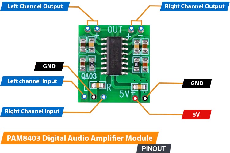
📘 Overview
The HW-104 PAM8403 is a compact 2×3W mini audio amplifier. It runs on 5 V and can drive 4–8 Ω speakers, delivering clear and powerful sound in a very small form factor (30×25×30 mm). Its Class D design with LC filter ensures low noise and minimal crosstalk, making it ideal for small audio projects.
PAM8403 PinOUT quartzcomponents.com
🔍 How It Works
It amplifies low-power audio signals from a microcontroller or audio source and outputs them to speakers or coils.
🔌 Pinout
The HW-104 PAM8403 mini audio amplifier has 6 pins:
| Pin | Description |
|---|---|
| VCC / Vin | Connect to 5 V power supply |
| GND | Ground |
| IN+ / IN- | Audio input |
| SPK+ / SPK- | Speaker output |
⚙️ Technical Specifications
| Specification | Value |
|---|---|
| Output Power | 2×3 W |
| Speaker Impedance | 4–8 Ω |
| Operating Voltage | 5 V |
| Dimensions | 30 × 25 × 30 mm |
| Amplifier Type | Class D with LC filter |
💥 15A 400W High-Power MOSFET Trigger Switch Drive Module

📘 Overview
The MOSFET Trigger Switch Dual High Power 15A 400W module is an electronic component designed to act as a power relay or high-current switch. It allows a low-voltage, low-current signal (like the PWM output from the XIAO ESP32-S3) to safely control high-power loads (like motors, heating elements, or high-current LED strips).
The module primarily uses an N-Channel MOSFET for Low-Side Switching, meaning it switches the ground connection of the load.
15A 400W High-Power MOSFET Trigger Switch Drive Module amazon.com
🔍 How It Works
- The XIAO ESP32-S3 sends a low-voltage signal ($\mathbf{3.3 \text{V}}$) to the Signal/Gate pin.
- This small voltage is enough to "open" the internal MOSFET (Metal-Oxide-Semiconductor Field-Effect Transistor).
- Once open, the MOSFET allows the high current from the external VDC (Motor Power) supply to flow through the Load (the Mini Vibration Motor).
- By using PWM (Pulse Width Modulation) on the input signal, the MOSFET rapidly switches ON and OFF, allowing for precise speed/intensity control of the vibration motor.
🔌 Pinout and Connection
The MOSFET module has two main sections: Control (Input) and Load (Output).
| Section | Pin/Terminal | Connects to | Function |
|---|---|---|---|
| Control | Signal/Gate | GPIO PWM (XIAO) | Receives the control signal (e.g., PWM for speed). |
| GND (Logic) | GND (XIAO) | Common ground reference for the control signal. Must be connected to Power GND. | |
| Load | Load+ | VDC Positive | Input terminal for the external motor power supply. |
| Load- | Motor Negative Lead | Connects the load's negative terminal to the MOSFET switch. |
Critical Note: A $\mathbf{1N4007}$ Flyback Diode must be wired in parallel with the motor to protect the MOSFET from reverse voltage spikes (Back-EMF).
⚙️ Technical Specifications
| Specification | Value | Relevance to Project |
|---|---|---|
| Load Voltage (VDC) | $\mathbf{5 \text{V}}$ - $\mathbf{36 \text{V}}$ | Range for the external power supply. |
| Max Continuous Current | $\mathbf{15 \text{A}}$ | Provides a large safety margin for the small vibration motor. |
| Max Power | $\mathbf{400 \text{W}}$ | Module's maximum switching capacity. |
| Control Voltage | $\mathbf{3.3 \text{V}}$ - $\mathbf{20 \text{V}}$ | Fully compatible with the $\mathbf{3.3 \text{V}}$ logic of the XIAO ESP32-S3. |
| Switching Type | N-Channel Low-Side | Switches the ground side of the circuit. |
🧪 Learn More
- 📘 Low-Side Switching: The MOSFET is placed between the load and ground. This is the most common and simplest method for DC motor control.
- 🛡️ Inductive Load Protection: The Mini Vibration Motor is an inductive load. Switching it off generates a voltage spike (Back-EMF). The Flyback Diode $\mathbf{1N4007}$ is essential to safely dissipate this spike away from the MOSFET.
- 🔗 Understanding MOSFETs for Arduino (SparkFun guide)
📳 Vibrating Mini Motor Disc
 Vibrating Mini Motor Disc adafruit.com
A compact, low-profile motor, flat design (Pancake Motor) is essential for providing haptic feedback in e-textile/wearable projects.It generates vibration using an internal Eccentric Rotating Mass (ERM) mechanism. Intensity is precisely controlled via PWM signals from the XIAO through a MOSFET driver.
- The motor works best at a nominal voltage of 3V DC (operating range: 2V to 5V).
- Because it draws around 60 mA at 3V, it must be driven using an external MOSFET module.
- The red wire (+) connects to the external power supply (VDC), and the blue/black wire (–) connects to the LOAD– terminal on the MOSFET module.
🛡️ Critical Safety Note
As an inductive load, the motor generates destructive voltage spikes (Back-EMF). To protect the MOSFET module from damage, a $\mathbf{1N4007}$ Flyback Diode must be placed in reverse parallel across the motor's two terminals.
References & Inspiration
This research grows from the meeting point between fashion, the body, and technology, exploring how materials can become sensitive, luminous, and responsive. The reference images show textiles that breathe, surfaces that shift color, garments that react to movement, and fabrics that translate the invisible data around us.
What inspires me is the idea of wearables as an expanded skin: a second surface that listens, reacts, vibrates, and communicates. I’m drawn to projects where light, sound, or temperature changes reshape perception, softening the boundary between body and environment.
Together, these inspirations outline a vision where textiles become interfaces, gestures become inputs, and clothing becomes a narrative tool—capable of mediating emotions, data, and sensory experiences.
 Wearables Inspiration Moodboard by Carlotta Premazzi
- Light Tissue by Sofía Guridi sofiaguridi.xyz
- Second Skins Re-FREAM by Malou Beemer maloubeemer.com
- Hemisphere / Bernhard Leitner Halfpipe, at iii instrumentinventors.org
- The Aurora Swarovski LED Dress by CuteCircuit djstormsblog.com
- Color-changing resin tops and dresses shift with heat-activated technology by Kim Mesches bkmag.com
- Connextyle: Techstyle for Rehabilitation, a muscle activity tracking garment for rehabilitation. Copyright Jessica Smarsch, photo by Lisa Klappe re-fream.eu
Talking Textle, Light Tissue by Sofia Guridi, New York Textile Month Youtube Channel
Wifitapestry by Richard Vijgen, Thermochromic wall hanging changes colour in response to Wi-Fi signals wifitapestry.com
Dezeen
References & Inspiration
-
Thermochromic screenprint - Ruby Lennox - FabLab Bcn
-
Led responsive glove - Marion Guillaud - Le TextileLab lyon
-
Thermochromic and sound research - Stephanie Johnson - TextileLab Amsterdam
-
Interactive glove - Stephanie Vilayphiou- Green Fabric
Process and workflow
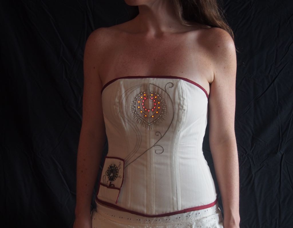
SOUND ACTUATOR - Wearable Soft Speakers

This project explores how magnetic induction and embroidered coils can be used to create soft, flexible, textile-based speakers. Instead of embedding rigid speaker components inside clothing, these wearable systems use fabric, conductive thread, and small magnets to generate sound. Inspired by work from e-textile pioneers like Leah Buechley, Hannah Perner-Wilson Sources NYC Resistor : Noisy Textiles, Instructables, Makezine, Institute for Future Technologies.
- Sew Wearable Soft Speakers - Make makezine.com
- Sound is pressoure wave created by an object when it vibrates.flippingphysics.com
Soft speakers combine craft, electronics, and e-textiles, turning garments into resonant, sounding surfaces.
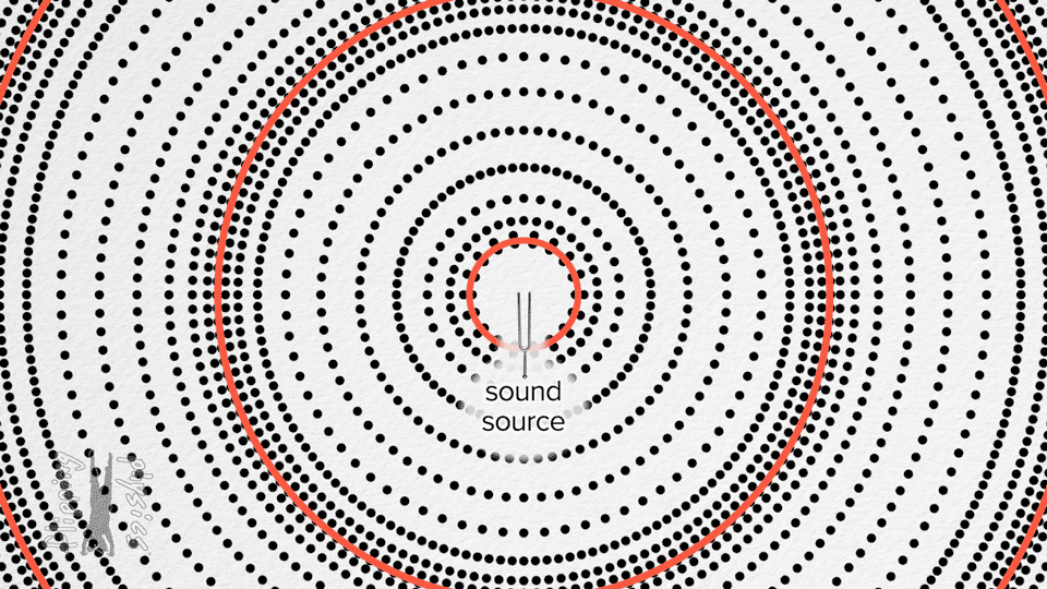
🧲 Electromagnetic Sound
Traditional speakers use: * a permanent magnet * a voice coil * a diaphragm
When an electrical signal runs through the coil, it creates a magnetic field that pushes and pulls against the magnet, vibrating the diaphragm and producing sound waves. Soft speakers recreate the same mechanism, but using textiles:
- Textile coil → a spiral stitched from conductive thread
- Fabric diaphragm → the textile itself becomes the vibrating membrane
- Magnet → placed behind or above the fabric without touching
- Amplifier → drives the coil with an audio signal
The result is a flexible, wearable, fabric-based speaker that can be embedded into garments, accessories, and soft objects.
🔌 How It Works
When a magnet moves near a coil, the changing magnetic field induces a small electrical signal (Faraday’s Law).
When an amplifier then sends an audio signal through that same textile coil, the alternating current creates a magnetic field that interacts with the fixed magnet. This push–pull interaction causes tiny vibrations in the fabric — which acts as the diaphragm — and these vibrations move air, producing audible sound.
Electricity → Magnetic Field → Motion → Sound
In essence: the coil generates a magnetic field from the audio signal, the magnet pushes and pulls against that field, the fabric vibrates and becomes a speaker membrane.
Build Your Wearable Soft Speaker
Tools
- Conductive thread/Copper wire/copper tape
- Fabric (cotton, felt, jersey, nonwoven)/Paper/ thin plastic base
- Permanent magnet (neodymium recommended)
- Audio amplifier board (PAM8403, MAX98357, etc.)
- Audio source (Microcontroller XIAO ESP32C3 / Arduino/ MP3 player / phone)
- Sewing tools (needle, hoop, scissors)
- 5V power source From USB or Li-Po battery
Build Your Wearable Soft Speaker Steps
- Design the Pattern
- Draw a spiral or concentric circle coil.
-
Leave space for the magnet — it must not touch the fabric.
-
Stitch the Coil
- Embroider the spiral using conductive thread.
-
Keep stitches tight, evenly spaced, and smooth.
-
Position the Magnet
- Fix the magnet behind or above the stitched coil.
-
Avoid direct contact to prevent damping.
-
Connect the Electronics
- Attach both coil ends to your amplifier board.
-
Insulate exposed conductive thread where needed.
-
Power Up & Test
- Connect your audio source.
- Power the amplifier (USB or battery).
-
Play audio and check for vibration and volume.
-
Wear & Integrate
- Sew the speaker into garments like:
- Hoodies, gloves, cuffs
- Collars, hats, scarves
- Soft patches or badges
 Source:
* Fabrip Speaker Proprieties. Wearables Slides by Lisa Stark liza-stark.com
* Examples of geometric, organic and animated spiral patterns for soft speakers.
Nabil, S., Jones, L., & Girouard, A. (2021). Soft Speakers: Digital Embroidering of DIY Customizable Fabric Actuators. TEI '21: Fifteenth International Conference on Tangible, Embedded, and Embodied Interaction, 1–9.
https://doi.org/10.1145/3430524.3440630
* Different types of samples.
J. Hladikova, J. Navratil, e S. Bouzek, "Smart Textile Speaker," Documento Tecnico, 2025. https://epci.eu/wp-content/uploads/2023/10/2_8_PCNS_Smart-Textile-Speaker.pdf
Source:
* Fabrip Speaker Proprieties. Wearables Slides by Lisa Stark liza-stark.com
* Examples of geometric, organic and animated spiral patterns for soft speakers.
Nabil, S., Jones, L., & Girouard, A. (2021). Soft Speakers: Digital Embroidering of DIY Customizable Fabric Actuators. TEI '21: Fifteenth International Conference on Tangible, Embedded, and Embodied Interaction, 1–9.
https://doi.org/10.1145/3430524.3440630
* Different types of samples.
J. Hladikova, J. Navratil, e S. Bouzek, "Smart Textile Speaker," Documento Tecnico, 2025. https://epci.eu/wp-content/uploads/2023/10/2_8_PCNS_Smart-Textile-Speaker.pdf

- Folding Tips. Wearables Slides by Lisa Starkliza-stark.com

- Soft Speakers by Carlotta Premazzi
Tips for Better Sound
- Tighter, uniform coils → cleaner vibrations
- Avoid heavy or thick fabrics
- The magnet must be stable but not touching
- Larger coils = deeper tones; smaller coils = sharper tones
- Try multiple coils for stereo or surround effects
- Copper tape coils work well for non-wearable prototypes
Experimental Notes
- Coils made from copper tape can act as pickup sensors and produce sound directly from magnetic movement.
- Varying the coil geometry (spirals, hexagons, fractals) affects timbre.
- Adding an active electromagnet can create feedback loops, where motion feeds sound and sound feeds motion.

Soft Speakers Schematics ( Arduino Uno+mini audio amplifier PAM8403; Seeed Studio XIAO ESP32C3+mini audio amplifier PAM8403) by Carlotta Premazzi
Coil Speaker Circuit CODE (Tone Melody Example)
/*
🎶 Melody Example — Driving a Textile Coil Speaker

This sketch plays a short melody on a soft coil speaker (or any 8Ω speaker)
driven from Arduino pin 8 using the built-in `tone()` function.

📌 Circuit:
- Textile / embroidered coil speaker OR standard 8Ω speaker
- Connect one end to digital pin 8
- Connect the other end to GND
- (Optional) Add a small NPN transistor if the textile coil needs more current

🧠 Notes:
- Uses "pitches.h" for musical note frequencies.
- Each note duration is calculated from the note type.
- A short pause (30%) between notes improves clarity.

🔗 Based on:
Arduino Built-In Example “toneMelody”


https://www.arduino.cc/en/Tutorial/BuiltInExamples/toneMelody

This example code is in the public domain.
*/

#include "pitches.h"

// Notes in the melody
int melody[] = {
NOTE_C4, NOTE_G3, NOTE_G3, NOTE_A3, NOTE_G3, 0, NOTE_B3, NOTE_C4
};

// Note durations: 4 = quarter note, 8 = eighth note, etc.
int noteDurations[] = {
4, 8, 8, 4, 4, 4, 4, 4
};

void setup() {
// Iterate over the notes of the melody
for (int thisNote = 0; thisNote < 8; thisNote++) {

// Calculate note duration (quarter=1000/4, eighth=1000/8, etc.)
int noteDuration = 1000 / noteDurations[thisNote];
tone(8, melody[thisNote], noteDuration);

// Add a small pause between notes
int pauseBetweenNotes = noteDuration * 1.30;
delay(pauseBetweenNotes);

// Stop the tone before the next one
noTone(8);
}
}

void loop() {
// Repeat the melody continuously
for (int thisNote = 0; thisNote < 8; thisNote++) {

int noteDuration = 1000 / noteDurations[thisNote];
tone(8, melody[thisNote], noteDuration);

int pauseBetweenNotes = noteDuration * 1.30;
delay(pauseBetweenNotes);

noTone(8);
}

delay(2000); // Pause before repeating
}
Wearable Soft Speaker Test by Carlotta Premazzi
MOTION ACTUATOR - Vibration Motors & Haptic

Vibration Motors & Haptic Actuator montage by Carlotta Premazzi. Source: Wearables Slides by Lisa Starkliza-stark.com
How to Build a Vibration Motor Circuit
📳 Vibration Motors & 🖐️ Haptic+Velostat
Head-massage band that integrates vibration motors and Velostat pressure sensors. When the user presses a specific point on the temples, the Velostat detects the pressure and activates the vibration motor, producing a targeted, relaxing massage effect.
🎛 Head-Massage Band — Wearable Low-Power
🛠️ Materials & Setup
- Microcontroller: ARDUINO UNO/XIAO ESP32-S3
- Sensor: Velostat pad + 10kΩ resistors
- Actuator: Vibrating Mini Motor Disc + NPN transistor 2n2222
- Software: Arduino IDE.
🔌 Wiring Instructions
- Velostat pads form a voltage divider connected to A0 and A1 on the XIAO
- Motor powered by battery, controlled via MOSFET (gate → D6)
- Flyback diode across motor to protect circuit
- Common GND for XIAO, motor, and battery
🧩 How It Works
- MCU sleeps to save battery
- Reads both Velostat sensors on wake
- If both pressed, motor vibrates briefly
- Returns to sleep to conserve power
- Serial output available for TouchDesigner integration
💡 Wearable Tips
- Soft elastic band, Velostat lightly padded at temples
- Small, lightweight motor and battery pouch for comfort
- Using sleep modes + short vibration bursts ensures long battery life
Debounce Button Multi-State — FULL CODE
```cpp /* 📁 Debounce Button Multi-State 17-11-2025 by Carlotta Premazzi, Fabricademy file: Debounce-Button-Multi-State.ino
🔧 Description: This sketch reads a Velostat sensor as analog input and implements debouncing to reliably detect presses or pressure events. Each valid press/pressure cycles through multiple states, changing the behavior of a small vibration motor connected to the board.
🧠 How it works: - Analog input is read from a Velostat sensor (A0). - A debounce algorithm ensures that only stable transitions are counted. - appState cycles from 0 to stateMax on each valid press. - Motor behavior changes according to appState: 0) Motor off 1) Motor on continuously 2) Motor pulses at 1-second intervals
🧩 Required components: - Velostat sheet - Mini vibration motor - NPN transistor (2N2222) - Resistor 470 Ω (base) - LED + 220Ω resistor - Arduino Uno or compatible board - Breadboard + jumper wires
💡 Notes:
- Adjust debounceDelay or interval to tune responsiveness.
- Works with digital or analog readings for detecting presses.
*/
// Analog input pin where the Velostat sensor is connected
const int analogInPin = A0;
// Stores the raw analog reading from the Velostat int sensorValue = 0;
// Unused variable (kept for legacy reasons) int outputValue = 0;
// Temporary reading used as "button" state (0 or 1) int reading;
// Application state (multi-mode controller) // 0 = off // 1 = on // 2 = blinking/pulsing int appState = 0; int stateMax = 3; // Total number of states (0,1,2)
// Timing variable for blinking state unsigned long previousMillis = 0;
// Time interval for toggling output in state 2 (ms) const long interval = 1000;
// Pin definitions const int buttonPin = 14; // 14 = A0 used as a digital trigger const int ledPin = 9; // Output pin (LED or motor via transistor)
// Output state storage int ledState = HIGH; // Current ON/OFF state of the output pin
// Button logic storage int buttonState; // Stable (debounced) reading int lastButtonState = LOW; // Previous raw reading
// Debounce variables unsigned long lastDebounceTime = 0; // Time of last detected change unsigned long debounceDelay = 50; // Required stable time (ms)
void setup() { Serial.begin(9600); // Start serial for debug
pinMode(buttonPin, INPUT);        // Velostat → digital-style trigger
pinMode(ledPin, OUTPUT);          // LED or motor output

digitalWrite(ledPin, ledState);   // Apply initial state to output
}
void loop() {
// Read analog value from Velostat
sensorValue = analogRead(analogInPin);

// Print sensor value + current app mode
Serial.print(sensorValue);
Serial.println("   appState: " + String(appState));

// Convert analog reading to HIGH/LOW threshold
if (sensorValue > 950) {
    reading = 1;
} else {
    reading = 0;
}

// --------------------------------------------------
//                     DEBOUNCE
// --------------------------------------------------

// If the reading changes: could be noise or real press → reset timer
if (reading != lastButtonState) {
    lastDebounceTime = millis();
}

// If the reading stayed stable longer than debounceDelay:
if ((millis() - lastDebounceTime) > debounceDelay) {

    // If stable reading differs from last stable stored:
    if (reading != buttonState) {
        buttonState = reading;

        // Register a press only when reading goes HIGH
        if (buttonState == HIGH) {

            ledState = !ledState; // Toggle LED state

            // Cycle through app states 0 → 1 → 2 → 0
            if (appState < stateMax) {
                appState++;
            } else {
                appState = 0;
            }

            Serial.println("appState: " + String(appState));
        }
    }
}

// Save last reading
lastButtonState = reading;

// --------------------------------------------------
//                  OUTPUT BEHAVIOR
// --------------------------------------------------

if (appState == 0) {
    digitalWrite(ledPin, LOW);    // Always OFF
}
else if (appState == 1) {
    digitalWrite(ledPin, HIGH);   // Always ON
}
else if (appState == 2) {

    // Non-blocking blinking using millis()
    unsigned long currentMillis = millis();

    // Toggle after "interval" milliseconds
    if (currentMillis - previousMillis >= interval) {
        previousMillis = currentMillis;
        digitalWrite(ledPin, !digitalRead(ledPin)); // Flip state
    }
}
}
Testing at Biolab, Lisbon
Testing at Biolab, Lisbon
VISUAL ACTUATOR - Leds, Neopixel, Flexible LED Filament
💡RGBLed + Velostat + 🎛️ Arduino Uno/Seeed Studio XIAO-ESP32C3
Velostat Pillow [Velostat Pressure Sensor – RGB Color Change; Velostat Pressure → RGB Spectrum] (https://class.textile-academy.org/2026/carlotta-premazzi/assignments/week05/#velostat) on my E-Textile Assignment.
💡Neopixel Strip + ❤️ MAX30102 Heart Rate and Oxygen Sensor + 🎛️ Arduino Uno/Seeed Studio XIAO-ESP32C3
This tutorial guides you through connecting and programming the MAX30102 sensor and a Neopixel Strip using the Arduino Uno/XIAO ESP32-S3 to display sensor status (e.g., heart beat detection).
![]()
MAX30102 Heart Rate and Oxygen Sensor+Arduino Uno/XIAO ESP32C3+NeopixelStrip schematics by Carlotta Premazzi.
MAX30102 Description on E-Textile Assignment.
🛠️ Materials & Setup
- Microcontroller: ARDUINO UNOXIAO ESP32-S3
- Sensor: MAX30102 MAX30102 Heart Rate and Oxygen Sensor
- Actuator: Neopixel Strip
- Software: Arduino IDE with ESP32 Board Support and Adafruit MAX3010x Library.
🔌 Wiring Instructions
The MAX30102 sensor uses a two-wire communication protocol called I2C (SDA/SCL) to send data. The Neopixel uses a single digital data line.
❤️ MAX30102 Sensor Connections (I2C)
| Function | MAX30102 Pin | Connection on Arduino UNO | Connection on XIAO ESP32-C3 |
|---|---|---|---|
| Data Line (SDA) | SDA | Analog Pin A4 | Pin IO8 |
| Clock Line (SCL) | SCL | Analog Pin A5 | Pin IO9 |
| Power | VCC | 3.3V or 5V Pin | Pin 3V3 |
| Ground | GND | GND Pin | Pin GND |
🌈 Neopixel Strip Connections (Data & Power)
| Function | Neopixel Strip Pin | Connection on Arduino UNO | Connection on XIAO ESP32-C3 |
|---|---|---|---|
| Data Signal | Data In | Digital Pin 5 | Pin D5 (IO5) |
| Power | VIN | 5V Pin | 5V Pin |
| Ground | GND | GND Pin | GND Pin |
Critical Power and Protection Notes
- Common Ground: The GND pin of your microcontroller must always be connected to the GND of the Neopixel strip and any external power supply you use. This establishes a common reference point.
- External Power for Neopixels: If you use more than 5 to 10 LEDs, the microcontroller cannot supply enough current. You must power the Neopixel strip from a separate, robust 5V external power supply (like a wall adapter or large power bank).
- Data Line Protection: Place the 330 Ohm resistor between the microcontroller's data pin (Pin 5 or D5) and the Data In pin on the Neopixel strip.
- Power Smoothing: Connect the recommended 1000uF capacitor across the 5V and GND lines of the Neopixel strip. This prevents sudden power spikes that can damage the first LED.
Heartbeat-Responsive LED Strip System — FULL CODE
/*
  Heartbeat-Responsive LED Strip System
17-11-2025 by Carlotta Premazzi, Fabricademy
  file: Heartbeat-Responsive-LED-Strip-System.ino
-------------------------------------------------------------
This program:

• Reads heart rate data (IR value) from MAX30105.
• Computes a dynamic minimum and maximum of the IR signal.
• Normalizes the IR signal for visual animations.
• Detects heartbeats in real time using checkForBeat().
• Calculates BPM + a smoothed rolling average.
• Drives a 100-LED NeoPixel strip with two animations:
    1) Continuous red "breathing" glow based on IR signal.
    2) A heartbeat-triggered wave that expands along the strip.

Hardware:
- MAX30105 Heart Rate Sensor (red LED only)
- Adafruit NeoPixel LED Strip (100 LEDs)
- Microcontroller with I2C + digital output (ESP32, Arduino…)


**************************************************************/

// 🔌 1. Import required modules
#include <Wire.h>              // I2C communication
#include "MAX30105.h"           // Heart rate sensor library
#include "heartRate.h"          // Beat detection algorithm
#include <Adafruit_NeoPixel.h>  // LED strip control

// 🔦 2. LED Strip Setup
#define LED_PIN 5               // Pin controlling the NeoPixel strip
#define NUM_LEDS 100            // Number of LEDs on the strip
Adafruit_NeoPixel strip(NUM_LEDS, LED_PIN, NEO_GRB + NEO_KHZ800);

// ❤️ 3. Heart Sensor Variables
MAX30105 heartSensor;
const int NUM_HEART_READINGS = 30;
int heartReadings[NUM_HEART_READINGS];
int heartReadingIndex = 0;
int32_t irValue;
float dynamicMin = 0;
float dynamicMax = 0;
float dynamicThreshold = 0;
float thresholdSmoothingFactor = 0.8;

// 🔧 4. BPM Variables
const byte RATE_SIZE = 4;
byte rates[RATE_SIZE];
byte rateSpot = 0;
uint32_t lastBeat = 0;
float beatsPerMinute;
int beatAvg;
bool BEAT = false;

// ▶️ 5. Setup()
void setup() {
Serial.begin(115200);
delay(2000);
strip.begin();
strip.show();
strip.setBrightness(180);
Wire.begin();

if (!heartSensor.begin(Wire, I2C_SPEED_FAST)) {
    Serial.println("MAX30105 not found. Check wiring.");
    while (1);
}

heartSensor.setup();
heartSensor.setPulseAmplitudeRed(0x0A);
heartSensor.setPulseAmplitudeGreen(0);
}

// 🔁 6. LOOP — Core system logic
void loop() {
readHeartSensor();
updateThreshold();
calculateBPM();

float norm = (irValue - dynamicMin) / (dynamicMax - dynamicMin);
if (norm < 0) norm = 0;
if (norm > 1) norm = 1;

animatePulse(norm);
animateBeatWave();

Serial.print("IR="); Serial.print(irValue);
Serial.print(" Min="); Serial.print(dynamicMin);
Serial.print(" Max="); Serial.print(dynamicMax);
Serial.print(" BPM="); Serial.print(beatsPerMinute);
Serial.print(" Avg="); Serial.println(beatAvg);

delay(10);
}

// 6.1. Read IR Value + store in circular buffer
void readHeartSensor() {
irValue = heartSensor.getIR();
heartReadings[heartReadingIndex] = irValue;
heartReadingIndex = (heartReadingIndex + 1) % NUM_HEART_READINGS;
}

// 6.2. Compute dynamic min/max + smoothed threshold
void updateThreshold() {
dynamicMin = heartReadings[0];
dynamicMax = heartReadings[0];

for (int i = 1; i < NUM_HEART_READINGS; i++) {
    if (heartReadings[i] < dynamicMin) dynamicMin = heartReadings[i];
    if (heartReadings[i] > dynamicMax) dynamicMax = heartReadings[i];
}

int newThreshold = dynamicMin + ((dynamicMax - dynamicMin) * 0.5);
dynamicThreshold =
    thresholdSmoothingFactor * dynamicThreshold +
    (1.0 - thresholdSmoothingFactor) * newThreshold;
}

// 6.3. Beat detection + BPM + Rolling average
void calculateBPM() {
if (checkForBeat(irValue)) {
    BEAT = true;
    uint32_t now = millis();
    uint32_t delta = now - lastBeat;
    lastBeat = now;
    beatsPerMinute = 60.0 / (delta / 1000.0);

    if (beatsPerMinute < 255 && beatsPerMinute > 20) {
        rates[rateSpot++] = (byte)beatsPerMinute;
        rateSpot %= RATE_SIZE;

        beatAvg = 0;
        for (byte x = 0; x < RATE_SIZE; x++) beatAvg += rates[x];
        beatAvg /= RATE_SIZE;
    }
} else {
    BEAT = false;
}
}

// 🌟 7. Animation 1 — Continuous Red Breathing
void animatePulse(float norm) {
int brightness = norm * 255;
for (int i = 0; i < NUM_LEDS; i++) {
    strip.setPixelColor(i, strip.Color(brightness, 0, 0));
}
strip.show();
}

// 🌊 8. Animation 2 — Heartbeat Expansion Wave
int wavePos = -1;

void animateBeatWave() {
if (BEAT) wavePos = 0;

if (wavePos >= 0) {
    for (int i = 0; i < NUM_LEDS; i++) {
        int dist = abs(i - wavePos);
        int val = max(0, 255 - dist * 40);
        strip.setPixelColor(i, strip.Color(val, 0, 0));
    }
    strip.show();
    wavePos++;
    if (wavePos >= NUM_LEDS) wavePos = -1;
}
}

Component Connections, Serial Monitor Reading By Carlotta Premazzi
Testing at Biolab, Lisbon
🔥 Thermochromic Dye (Heat-Reactive) for Natural Fibers
Goal: An ink system that is lightly affixed to natural fibers, enabling visible color change with temperature while maintaining the fabric's soft texture. Ideal For: Soft, breathable fabrics that respond to body heat, breath, or sunlight.
ingredients (semi-natural / low-tox): • thermochromic pigment powder → microencapsulated, reacts at 30–40 °c → available online in various color transitions (e.g., black → transparent, red → yellow) • water-based carrier liquid: distilled water [+ apple cider vinegar (acidic, helps dye penetration)] or water + food-grade alcohol (max ~20%) • (optional light binder) a small amount of gum arabic (natural adhesive) or aloe vera gel (helps moisture retention, mildly fixes pigment) • [fixative after dyeing: heat set with an iron or heat press]
basic recipe: • 10 parts of your liquid base • add a tiny amount of gum arabic if you want better adhesion (e.g., 1 g per 50 ml) • stir thoroughly until well suspended • apply by dipping, brushing, or spraying onto the natural fabric • let dry for at least 24 hours • [heat set by ironing (no steam) or pressing at up to 120 °c (250 °f) for a few minutes]
result: the dye soaks into the fibers, keeping the fabric soft and breathable. the color fades or changes when exposed to heat (e.g., touch, breath, sunlight). works best on light-colored or untreated fabrics.
Lecture on November 12th, 2025, Global Instructors: Liza Stark, Local Instructors: Guilherme Martins, Carlos Roque.
- **Workshops
- Global Tutorial: Microcontroller and Outputs by Emma Pareschi
🔗 References & Tutorials
Concept & Inspiration
- Interactive Fashion – Google Arts & Culture
- Adafruit Flora & NeoPixel wearables tutorials
- Shintake et al., Soft Actuators for Wearables, 2021
- Mann, S. (1996). “Smart clothing.” Proceedings of the Fourth ACM International Conference on Multimedia - MULTIMEDIA '96
- Nabil, S., Jones, L., & Girouard, A. (2021). Soft Speakers: Digital Embroidering of DIY Customizable Fabric Actuators. TEI '21
- Liza Stark. Data vows: reimagining ritual through eTextile practice. ISWC '17
- Planning a Wearable Electronics Project – SparkFun
Sensors (Inputs)
- Adafruit Learn Guide – Capacitive Touch Sensor with Arduino
- Velostat / Flex sensor tutorials for wearables
Actuators (Outputs)
- NeoPixel library documentation (Adafruit)
- DFPlayer Mini project tutorials
- SMA actuator studies for wearable haptics
Microcontrollers
- Arduino IDE documentation – ATtiny setup
- SparkFun ATtiny tutorial
Materials & Connections
- Leah Buechley, Textile Interfaces for Wearable Electronics
- Adafruit tutorial: Conductive Thread Basics
Power Considerations
- LiPo / Coin cell battery guides (Adafruit)
Tools & Software
- Arduino IDE tutorials
- Fritzing guides for wearable circuits
Student checklist
- [ ] Document the concept, sketches, references also to artistic and scientific publications
- [ ] Create a swatch/sample using a microcontroller with one input and one output, using hard-soft connection solutions and battery
- [ ] Create 2 actuator swatches and test them, chosing from examples such as: motors / mini vibration leds / neopixels flip dot / electromagnet heat pad / with thermochromic coating speaker / mp3 player SMA (shape memory alloy)
- [ ] Learn how to program a microcontroller, documenting your process, the libraries added, power requirements and source code
- [ ] Document the schematic and circuit Upload a small video of your object working
- [ ] Integrate it to a project (extra credit)