8. W E A R A B L E S
Introducing...
T E C H S T Y L E S
I N S P I R A T I O N
T A K I S
Plato speaks of an artist turning the invisible world into the visible. I hope that someone seeing my sculpture is lifted out of his ordinary state.
-Takis
Artist Takis made sculptures that combine science and technology with natural phenomena, ancient art and music.
Panagiotis ‘Takis’ Vassilakis was born in Athens in 1925
Self taught sculptor, starting with plaster figures inspired by Alberto Giacometti, then inspired by kinetic movement and later experimenting with magnets and the magnetic field.
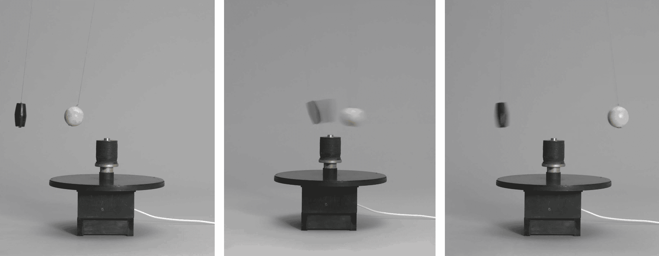
Takis, Magnetic Ballet 1961
As well as using magnetic energy to float objects in space, and interact, Takis used magnets to generate resonant sounds.
His installation Electro-Magnetic Musical 1966 consists of a white panel with a guitar string stretched across its width and a large needle suspended in front of it.
The musical string is are attached to an amplifier and an electro magnet is concealed behind each panel.
The magnets attract and repel the needles so they strike or grate against the string, creating vibrations that are amplified and played through speakers placed at the top of the panels.
I cannot think of my work as entirely my work. In a sense, I’m only a transmitter, I simply bathe in energy.
-Takis
R E S E A R C H
Caress of the Gaze by Behnaz Farahi
Interactive 3D printed wearable garment that can can detect other people’s gaze and respond accordingly with life-like behavior.
Caress of the Gaze from Charlie Nordstrom on Vimeo.
On further research it appears that the main shape-changing mechanism incorporates Shape Memory Alloy (Actuation System).
Read more here
T U T O R I A L S
Fabricademy Videos
Wearable - Arduino & Outputs slides
ATTiny and Touch Sensors 22-23
Tutorial Arduino and Power Loads 21-22
Arduino, Neopixels and Sound 21-22
R E F E R E N C E
M A T E R I A L S
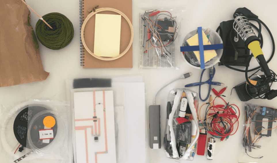
Lots and lots and lots of materials!
Some integral pieces of equipment =
B R E A D B O A R D
Breadboard = circuit-building platform which enables you to connect mutiple components without committing to soldering
~ number (wave number) means you can change more for example: fade
Breadboard Anatomy
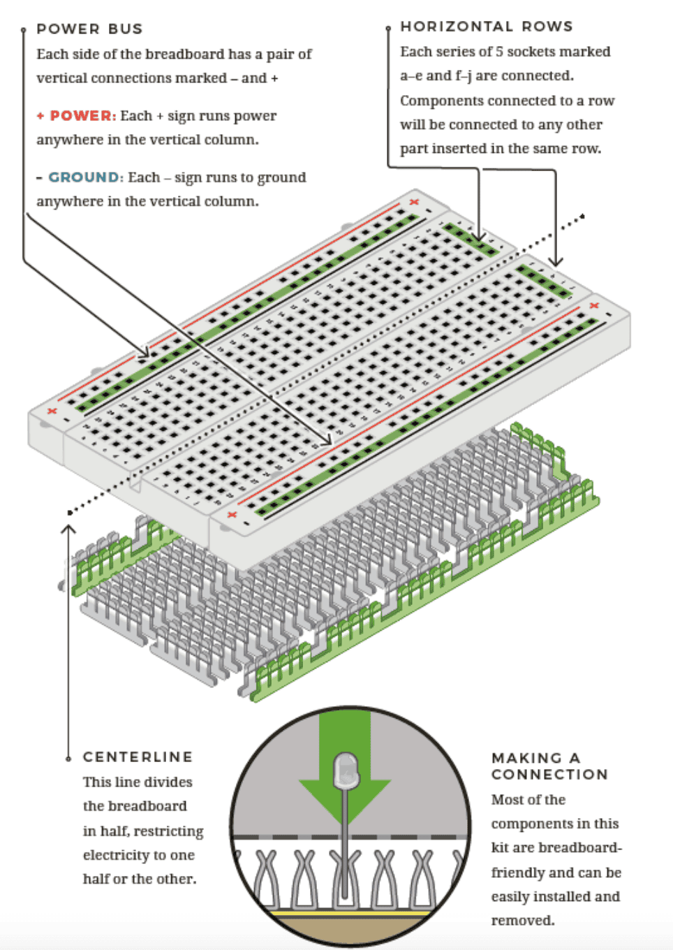
Photo & more information at What is a Breadboard?
L I B R A R Y
A library = set of functions that are ready to be used (not automatically installed in Arduino IDE; you need to install it)
A T t i n y
Programming the ATtiny 85
Note when connecting ATtiny
-
ATtiny must be connected in the middle of breadboard
-
Orientation is important (dot should be facing the top and aligned with red power wire connected to 5V on Arduino)
Step 1. Add ATtiny85 to Arduino URL Board Manager
-
Arduino -> Preferences then scroll down to Additional Board Managers URLs
-
Copy and paste this link:
https://raw.githubusercontent.com/damellis/attiny/ide-1.6.x-boards-manager/package_damellis_attiny_index.json
Step 2. Install the ATtiny Board
-
Tools -> Board -> Boards Manager
-
Attiny tab will open
-
Select Install on the Attiny by David. A Mellis
-
Tools--> Board-->Attiny85
Step 3. Set the Arduino Uno Into ISP Mode
-
File -> Examples -> 11. Arduino ISP -> ArduinoISP
-
ISP sketch should open and upload it to your Arduino Uno
Step 4. Connecting the Arduino to the ATtiny Pins
- Use a breadboard, wires and capacitor-10uF (short leg to GND) to make the connections from the Arduino Uno to the ATtiny85
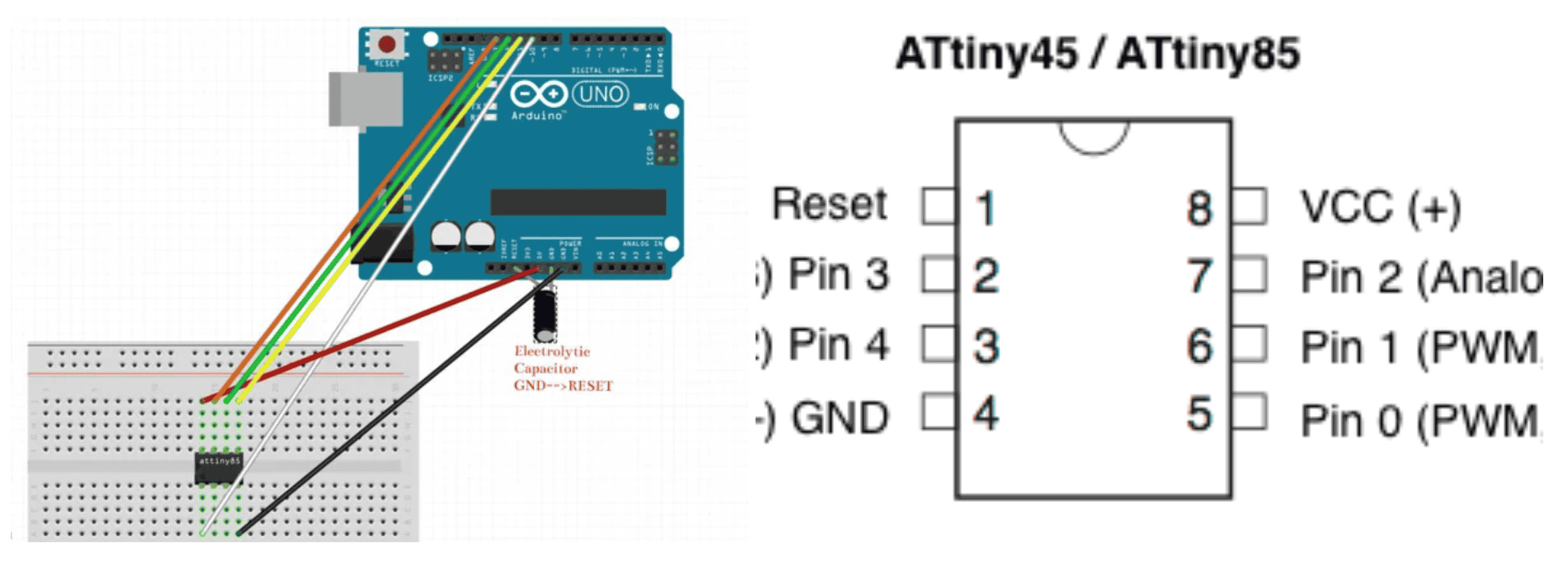
Connecting pins for Arduino Uno and ATtiny85
                                Arduino  ->   ATtiny85

                                5V            Vcc
                                GND           GND
                                Pin 13        Pin 2
                                Pin 12        Pin 1
                                Pin 11        Pin 0
                                Pin 10        Reset
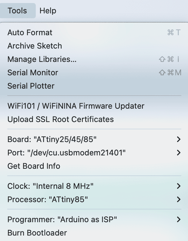
Step 5. Making ATtiny85 Arduino Compatible
-
Tools -> Board -> ATtiny25/45/85
-
Tools -> Processor -> Clock -> 8 MHz (internal)
-
Tools -> Programmer -> Arduino as ISP
-
Tools -> Burn Bootloader
Step 6. Uploading Sketch
-
Test that the ATtiny85 can now receive sketches from the Arduino IDE
-
File -> Example -> 01.Basics -> blink
-
Change pin 13 with 0
-
Ensure ATtiny85 board settings remain
-
Upload the sketch
-
Connect LED: anode (+) to pin 0 (physical pin 5 ) and the cathode (-) to a 1K resistor connected to ground (physical pin 4)
-
Sketch -> Upload using programmer
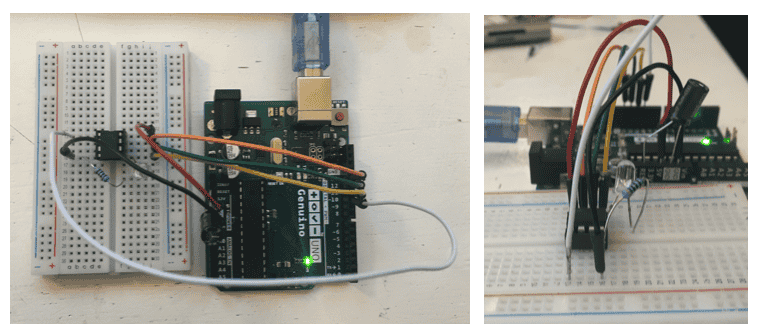
I mainly followed this tutorial: How to Program an Attiny85 From an Arduino Uno
After programming the ATtiny, I tested it to see if I could make a stand alone circuit and not connected to Arduino Uno and computer.
ATtiny 85 stand alone (LED light powered by 4.5 V battery pack)
T R A N S I S T O R
Transistor = active component.
Changes based on the Voltage applied to Gate pin
Driver circuit = allows you to control a Power Load with low Voltage (Arduino) but the Current for the Load in sinked by a difference source (transistor in this case)
-
If Voltage on the gate is high = transistor is like a close switch.
e.g. Vgs = 5V = current can flow -
If Voltage on the gate is low = transistor is like an open switch.
e.g. Vgs = 0V = current can’t flow
Can use function in Arduino IDE:
analogWrite to control the amount of Current that flows through the transistor and the power load.
analogWrite(pin 0,255);
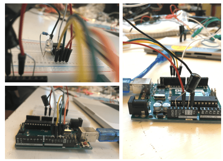
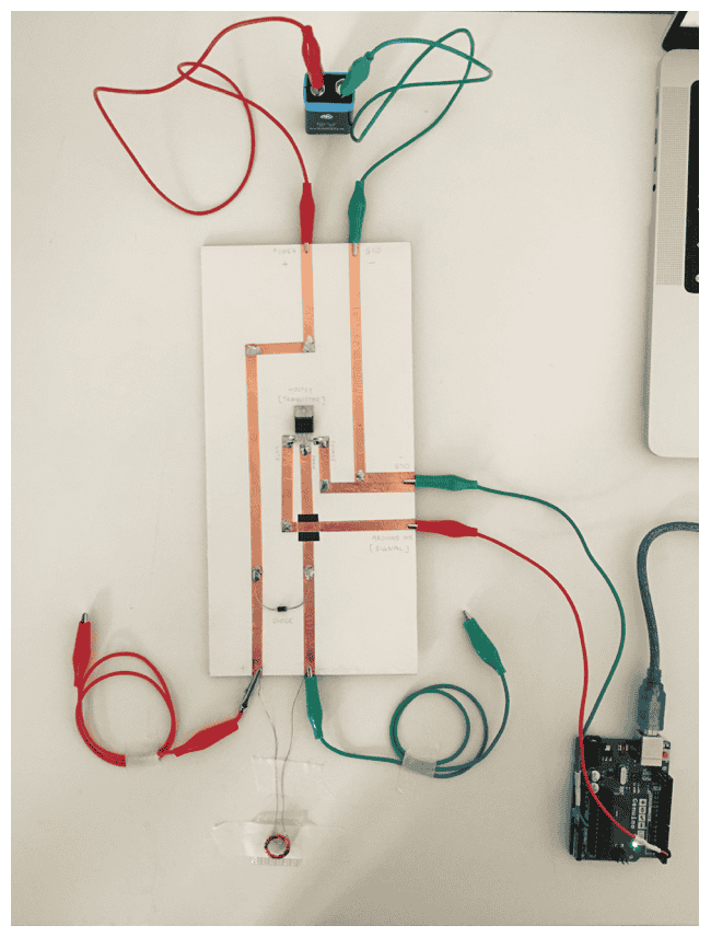
BUILD DRIVER CIRCUIT
Materials =
Transistor = IRL3103 MOSFET Data Sheet
Diode = Diode 1N4001 (In this configuration the diode is called flyback diode, used to protect the mosfet)
Conductive tape, solder, soldering iron, insulation tape, cardboard, crocodile clips and Arduino Uno
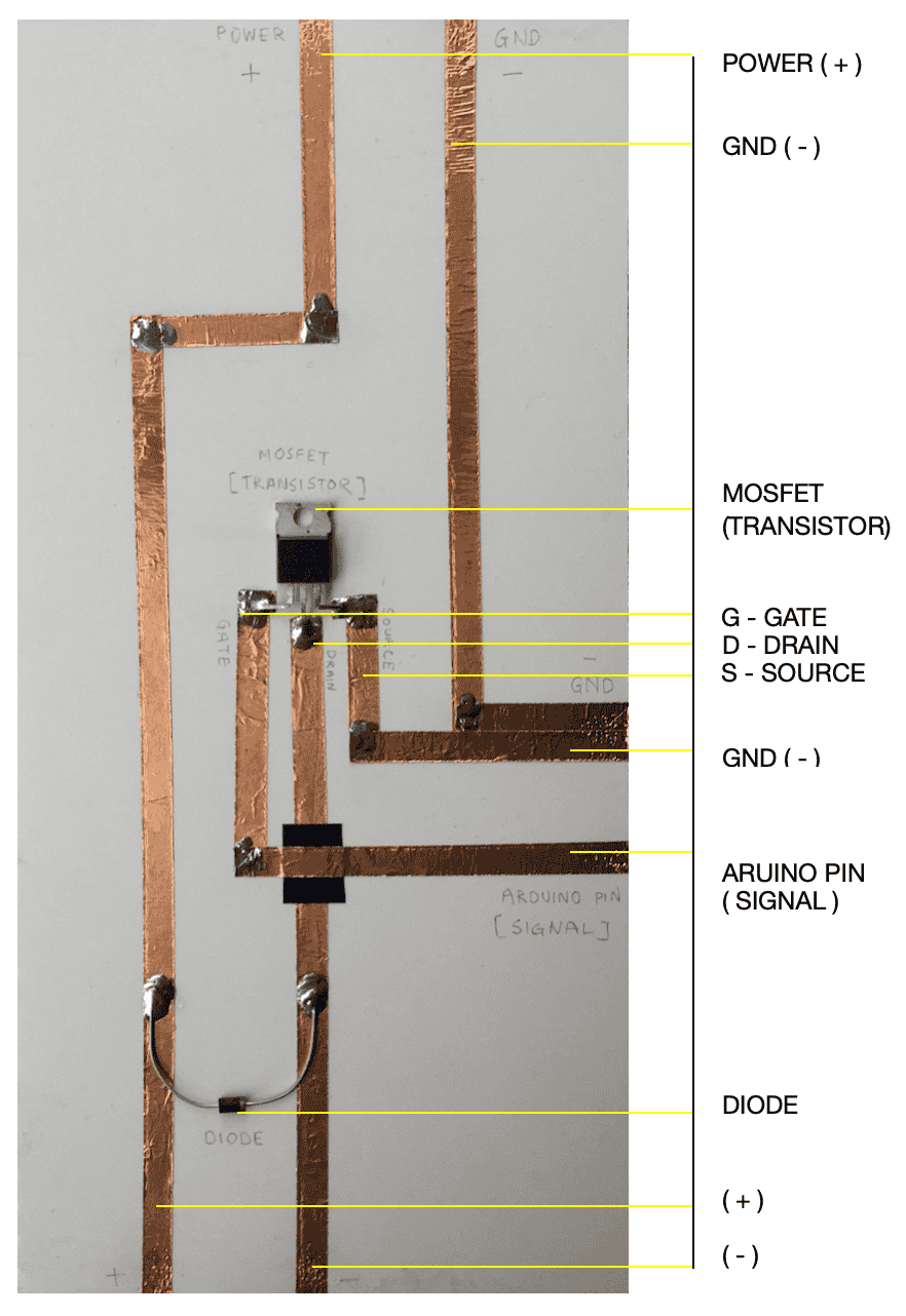
NOTE
-
Be sure to solder edges of conductive tape (check connections and conductivity later using multimeter)
-
Ensure Diode orientation is correct (grey strip in the dirrection of Drain)
-
Ensure Mosfet is in correct dirrection (metal piece face down + GDS higher up)
-
Bridge overlap between Gate and Drain using insulation tape
-
Ensure Source and GND (-) trace is connected
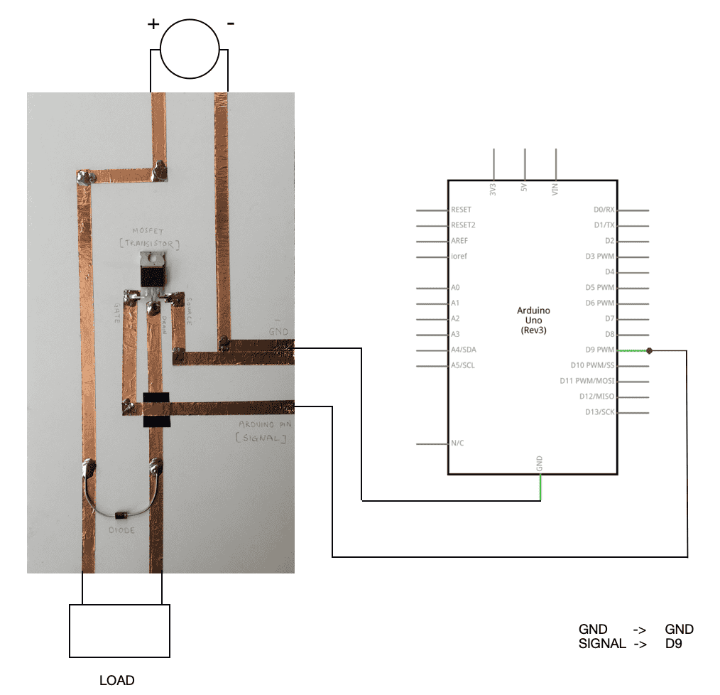
Schematic example of driver circuit complete
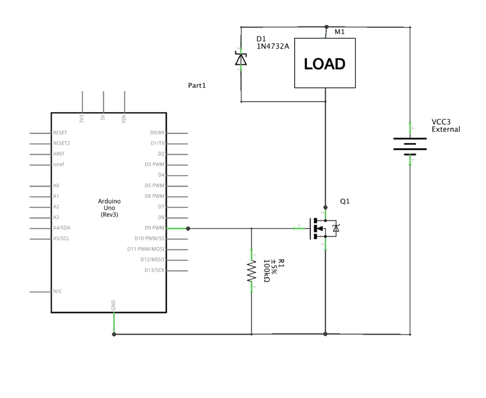
Built driver circuit with transistor connected to power, load & Arduino Uno
L D R
A LDR (light-dependent resistor) aka photoresistor = passive component that decreases resistance with respect to receiving luminosity (light) on the component's sensitive surface.
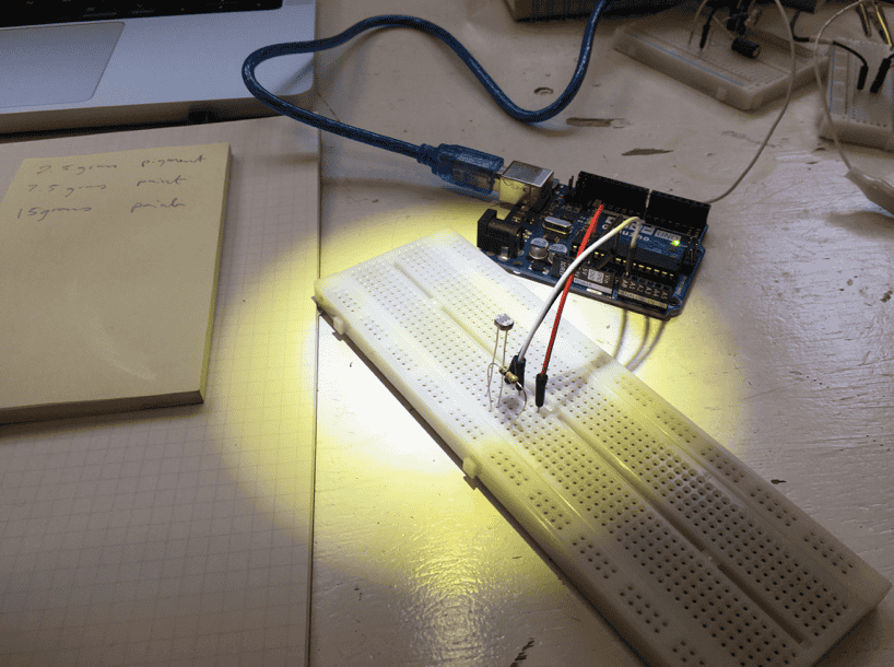
CODE
Make LED FADE using LDR
//set pin numbers
//const won't change
const int ledPin = 11;    //number of LED pin

const int ldrPin = A0;    //number of LDR pin

void setup() {

Serial.begin(9600);

pinMode(ledPin, OUTPUT);    //initialize LED pin as output

pinMode(ldrPin, INPUT);     //initialize LDR pin as input

}

void loop() {

int ldrStatus = analogRead(ldrPin);   //read status of the LDR value
Serial.print("initial value from ldr: ");
Serial.println(ldrStatus);
ldrStatus = map(ldrStatus, 170, 430, 0, 255);
analogWrite(ledPin, ldrStatus);
Serial.print("mapped value from ldr: ");
Serial.println(ldrStatus);

delay(1000);

}
A C T U A T O R
Component (output) = does something
Visual (change to the eyes) comes in the form of: LEDs one single source of light usually come in one colour or in RGB (red, green blue) 4 legs
Neopixels FiberOptics Thermochromic ink
Sound (change to the ears): Textile speakers
Motion (moves): Shape memory alloys Flip dots Vibe motors Haptics
V I S U A L
F I B E R _ O P T I C S
Technology that transmits information as light pulses along a glass or plastic fiber
-
End Emitting: thin, delicate, light shown out top/end
-
Side Emitting: thicker, flexible, nice all over glow
Testing Fiber Optics at the Lab:
-
Thinner size: produces faint light at end
-
Thicker size: produces faint all over glow transmitted throughout. Strong light at end (end emitting? cover = strong light?)
N E O P I X E L S
-
Smart RGB LED can program any colour
-
Sold in many forms: strips (can cut to size), rings, sewable
Using a strip LED's and an Arduino Uno, I first made the connections
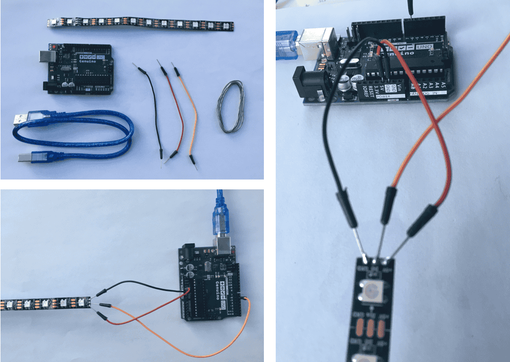
As NeoPixel is essentially an LED -> pay attention to the dirrection of the current
**** Follow the arrows !!!
I then programmed the strip using Arduino Ide
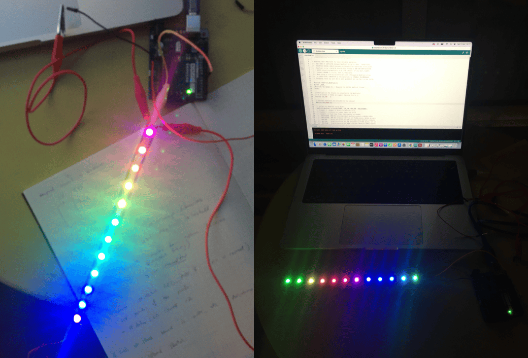
CODE
-
Need to send right sequence of command to input pin of neopixel
-
Which neopixel you want to control + which colour to display?
Step 1. Install the Neopixel Library in Arduino. Step 2. After that there are various examples you can modify
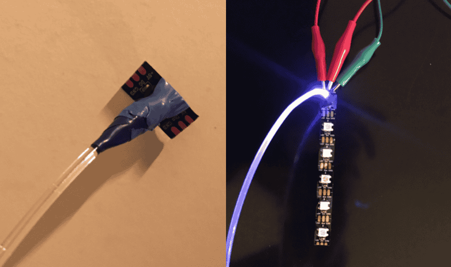
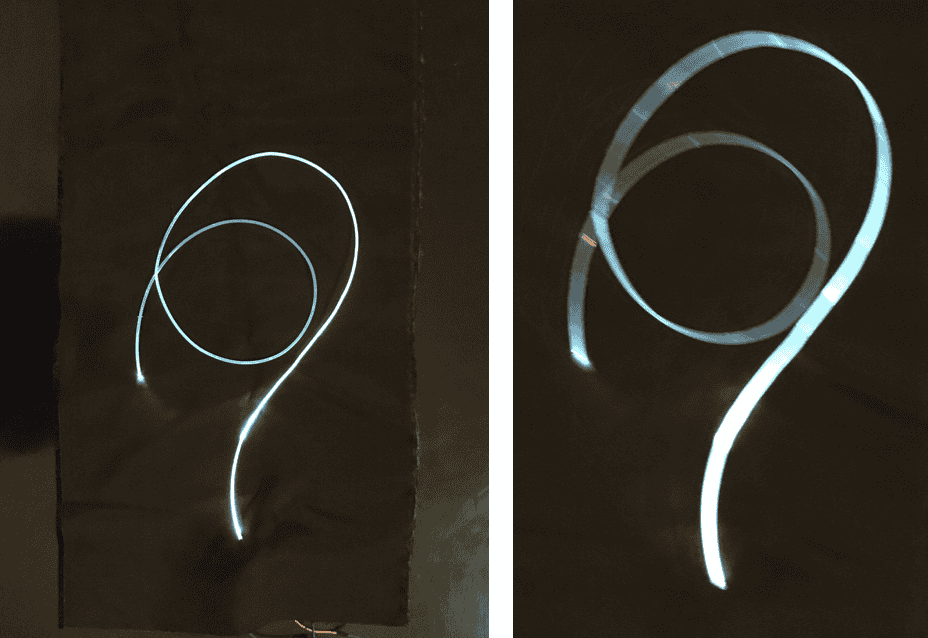
NeoPixels & Fiber Optics
I wanted to combine these two so that the light emitted out of ther fibers and you could easily control the light.
Step 1 : Code 1 NeoPixel to test the light
Connection
-
I imagine that the end would have to be cut very precisely to avoid any light leakage
-
Heat Shrink to connect the two together and avoid light leakage
-
Possibility to have NeoPixels split up (but still connected) and dispersed throughout garment
Testing Side emitting vs End emitting:
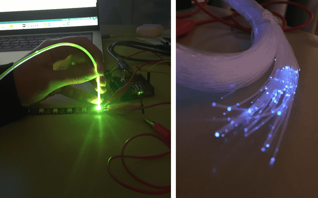
Making a hole in black fabric and poking Fiber Optic through.
Showing Fiber Optic embedded into fabric
Future
-
Fiber Optics -> Muscle Fibers. Embed multiple NeoPixels and Fiber Optics into a corset and stitch them down where the muscles go, programming lights to move so that it shows the human anatomy.
-
Play with long exposure
-
Explore the mechanics of fiber optics hula hoops and programming light designs.
Test 02
Incorporate fabric with NeoPixels
Diffuse the light = organza shapes
Step 1: Cut organza circles Step 2: Sew them into flowers
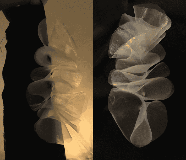
Step 3: Place NeoPixel strip under base fabric Step 4: Cut holes at each NeoPixel
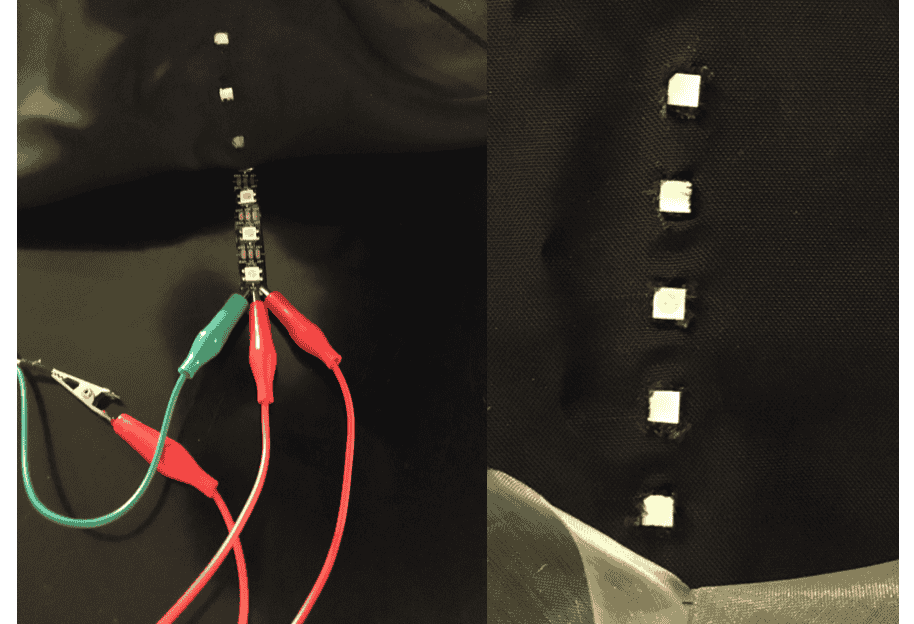
Step 5: Sew on the organza flowers at each NeoPixel Step 6: Program NeoPixels
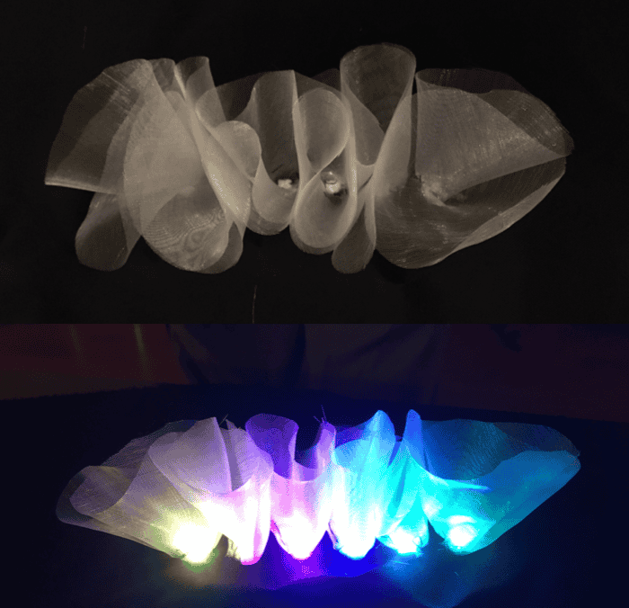
Result
NeoPixel Adafruit Sketch Example -> strandtest
// A basic everyday NeoPixel strip test program.

// NEOPIXEL BEST PRACTICES for most reliable operation:
// - Add 1000 uF CAPACITOR between NeoPixel strip's + and - connections.
// - MINIMIZE WIRING LENGTH between microcontroller board and first pixel.
// - NeoPixel strip's DATA-IN should pass through a 300-500 OHM RESISTOR.
// - AVOID connecting NeoPixels on a LIVE CIRCUIT. If you must, ALWAYS
//   connect GROUND (-) first, then +, then data.
// - When using a 3.3V microcontroller with a 5V-powered NeoPixel strip,
//   a LOGIC-LEVEL CONVERTER on the data line is STRONGLY RECOMMENDED.
// (Skipping these may work OK on your workbench but can fail in the field)

#include <Adafruit_NeoPixel.h>
#ifdef __AVR__
#include <avr/power.h> // Required for 16 MHz Adafruit Trinket
#endif

// Which pin on the Arduino is connected to the NeoPixels?
// On a Trinket or Gemma we suggest changing this to 1:
#define LED_PIN    6

// How many NeoPixels are attached to the Arduino?
#define LED_COUNT 6

// Declare our NeoPixel strip object:
Adafruit_NeoPixel strip(LED_COUNT, LED_PIN, NEO_GRB + NEO_KHZ800);
// Argument 1 = Number of pixels in NeoPixel strip
// Argument 2 = Arduino pin number (most are valid)
// Argument 3 = Pixel type flags, add together as needed:
//   NEO_KHZ800  800 KHz bitstream (most NeoPixel products w/WS2812 LEDs)
//   NEO_KHZ400  400 KHz (classic 'v1' (not v2) FLORA pixels, WS2811 drivers)
//   NEO_GRB     Pixels are wired for GRB bitstream (most NeoPixel products)
//   NEO_RGB     Pixels are wired for RGB bitstream (v1 FLORA pixels, not v2)
//   NEO_RGBW    Pixels are wired for RGBW bitstream (NeoPixel RGBW products)


// setup() function -- runs once at startup --------------------------------

void setup() {
// These lines are specifically to support the Adafruit Trinket 5V 16 MHz.
// Any other board, you can remove this part (but no harm leaving it):
#if defined(__AVR_ATtiny85__) && (F_CPU == 16000000)
clock_prescale_set(clock_div_1);
#endif
// END of Trinket-specific code.

strip.begin();           // INITIALIZE NeoPixel strip object (REQUIRED)
strip.show();            // Turn OFF all pixels ASAP
strip.setBrightness(50); // Set BRIGHTNESS to about 1/5 (max = 255)
}


// loop() function -- runs repeatedly as long as board is on ---------------

void loop() {
// Fill along the length of the strip in various colors...
colorWipe(strip.Color(255,   0,   0), 50); // Red
colorWipe(strip.Color(  0, 255,   0), 50); // Green
colorWipe(strip.Color(  0,   0, 255), 50); // Blue

// Do a theater marquee effect in various colors...
theaterChase(strip.Color(127, 127, 127), 50); // White, half brightness
theaterChase(strip.Color(127,   0,   0), 50); // Red, half brightness
theaterChase(strip.Color(  0,   0, 127), 50); // Blue, half brightness

rainbow(10);             // Flowing rainbow cycle along the whole strip
theaterChaseRainbow(50); // Rainbow-enhanced theaterChase variant
}


// Some functions of our own for creating animated effects -----------------

// Fill strip pixels one after another with a color. Strip is NOT cleared
// first; anything there will be covered pixel by pixel. Pass in color
// (as a single 'packed' 32-bit value, which you can get by calling
// strip.Color(red, green, blue) as shown in the loop() function above),
// and a delay time (in milliseconds) between pixels.
void colorWipe(uint32_t color, int wait) {
for(int i=0; i<strip.numPixels(); i++) { // For each pixel in strip...
    strip.setPixelColor(i, color);         //  Set pixel's color (in RAM)
    strip.show();                          //  Update strip to match
    delay(wait);                           //  Pause for a moment
}
}

// Theater-marquee-style chasing lights. Pass in a color (32-bit value,
// a la strip.Color(r,g,b) as mentioned above), and a delay time (in ms)
// between frames.
void theaterChase(uint32_t color, int wait) {
for(int a=0; a<10; a++) {  // Repeat 10 times...
    for(int b=0; b<3; b++) { //  'b' counts from 0 to 2...
    strip.clear();         //   Set all pixels in RAM to 0 (off)
    // 'c' counts up from 'b' to end of strip in steps of 3...
    for(int c=b; c<strip.numPixels(); c += 3) {
        strip.setPixelColor(c, color); // Set pixel 'c' to value 'color'
    }
    strip.show(); // Update strip with new contents
    delay(wait);  // Pause for a moment
    }
}
}

// Rainbow cycle along whole strip. Pass delay time (in ms) between frames.
void rainbow(int wait) {
// Hue of first pixel runs 5 complete loops through the color wheel.
// Color wheel has a range of 65536 but it's OK if we roll over, so
// just count from 0 to 5*65536. Adding 256 to firstPixelHue each time
// means we'll make 5*65536/256 = 1280 passes through this loop:
for(long firstPixelHue = 0; firstPixelHue < 5*65536; firstPixelHue += 256) {
    // strip.rainbow() can take a single argument (first pixel hue) or
    // optionally a few extras: number of rainbow repetitions (default 1),
    // saturation and value (brightness) (both 0-255, similar to the
    // ColorHSV() function, default 255), and a true/false flag for whether
    // to apply gamma correction to provide 'truer' colors (default true).
    strip.rainbow(firstPixelHue);
    // Above line is equivalent to:
    // strip.rainbow(firstPixelHue, 1, 255, 255, true);
    strip.show(); // Update strip with new contents
    delay(wait);  // Pause for a moment
}
}

// Rainbow-enhanced theater marquee. Pass delay time (in ms) between frames.
void theaterChaseRainbow(int wait) {
int firstPixelHue = 0;     // First pixel starts at red (hue 0)
for(int a=0; a<30; a++) {  // Repeat 30 times...
    for(int b=0; b<3; b++) { //  'b' counts from 0 to 2...
    strip.clear();         //   Set all pixels in RAM to 0 (off)
    // 'c' counts up from 'b' to end of strip in increments of 3...
    for(int c=b; c<strip.numPixels(); c += 3) {
        // hue of pixel 'c' is offset by an amount to make one full
        // revolution of the color wheel (range 65536) along the length
        // of the strip (strip.numPixels() steps):
        int      hue   = firstPixelHue + c * 65536L / strip.numPixels();
        uint32_t color = strip.gamma32(strip.ColorHSV(hue)); // hue -> RGB
        strip.setPixelColor(c, color); // Set pixel 'c' to value 'color'
    }
    strip.show();                // Update strip with new contents
    delay(wait);                 // Pause for a moment
    firstPixelHue += 65536 / 90; // One cycle of color wheel over 90 frames
    }
}
}
NeoPixels + ATtiny
- Use Arduino Uno + breadboard + all jumer wires to program ATtiny
- Check using LED or NeoPixels on breadboard to see if programmed sketch works
- Place ATtiny in stand alone project and test
NeoPixel + Ultrasonic Sensor + ATtiny
For my final project I wish to combine NeoPixels with an HY-SRF05 Ultrasonic Sensor, this must be stand alone so I plan to use an ATtiny 85 as a microcontroller.
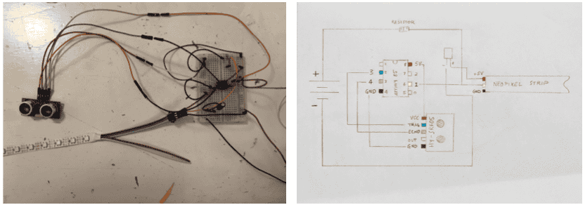
Right - Picture of wiring in breadboard
Left - Schematic drawing of Neopixels with an ATtiny 85 with Ultrasonic Sensor, 330 kΩ (Ohm) Resistor and a Polarized Capacitor
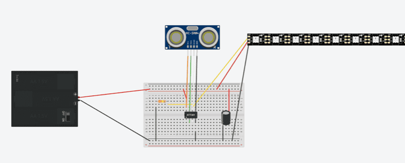
Schematic diagram of Neopixels with an ATtiny 85 with Ultrasonic Sensor, 330 kΩ (Ohm) Resistor and a Polarized Capacitor in a breadboard
It works! Powered by a 4.5 V battery pack (3 x 1.5 V batteries)
C O D E
Code to make the Neopixels work with the Ultrasonic Sensor & AtTiny
#include <NewPing.h>
#include <Adafruit_NeoPixel.h>

const byte triggerPin = 3;
const byte echoPin = 4;
NewPing distanceSensor(triggerPin, echoPin);

#define PIN        1 // pin on the Arduino connected to the NeoPixels
#define NUMPIXELS 8 // number of NeoPixels

Adafruit_NeoPixel pixels(NUMPIXELS, PIN, NEO_GRB + NEO_KHZ800);

#define DELAYVAL 500 // Time (in milliseconds) to pause between pixels

bool lightsOn = false;

void setup() {
    delay(1000);
    pixels.begin();
}

void loop() {
    // Every 500 milliseconds, do a measurement using the sensor and print the distance in centimeters.
    unsigned int distance = distanceSensor.ping_cm();


    // Check if the distance is 3cm or less
    if (distance <= 3) {
        // Toggle the lights on or off based on the current state
        if (lightsOn) {
            // Turn off NeoPixels gradually
            for (int i = NUMPIXELS - 1; i >= 0; i--) {
                pixels.setPixelColor(i, pixels.Color(0, 0, 0)); // Turn off pixel
                pixels.show();
                delay(50); // Adjust the delay to control the speed of turning off
            }
            lightsOn = false;
        } else {
            // Turn on NeoPixels gradually
            for (int i = 0; i < NUMPIXELS; i++) {
                pixels.setPixelColor(i, pixels.Color(0, 50, 50)); // Green color
                pixels.show();
                delay(50); // Adjust the delay to control the speed of turning on
            }
            lightsOn = true;
        }
    }

    delay(DELAYVAL);
}
NOTE:
-
Must download NewPing by Tim Eckel in Arduino Uno Library Manager
-
I had to delete any code with "Serial" to get it to work with ATtiny
-
Upload Sketch Upload Using Programmer
T H E R M O C H R O M I C
Once pigments reach a certain temperature = they change colour
Can control this state change with:
-
Body heat
-
Heat generated in a circuit
Results in a collaborative element
Variables
-
Pigment amount = higher ratio of pigment to base may take more time / energy to change
-
Base = ideally transparent / clear however different bases will determine different colours & affect transformation time
-
Material = the thinner gives a quicker transformation e.g. tracing paper is faster then canvas
-
Application = silkscreen printing gives best results. Paintbrush isn't great
-
Temperature = summer heat is not great, colder environment is better
-
Conductive Material = need just the right amount of resistance
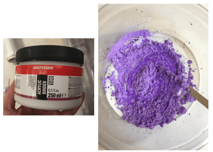
Recipe
I used a 1 : 6 ratio of pigment : medium
Each batch I measured out =
2.5 grams pigment +
15 grams medium
Materials
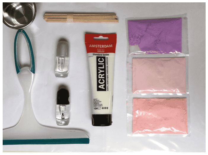
What fabric to use?
I felt there was little information online about what material exactly worked best with the thermochromic inks.
As I come from a Textiles background, I felt it was important to know does it make a difference to use certain fabrics.
I therefore carried out a test on 4 fabrics to see if the results differed:
I used Cotton, Synthetic Organza, Silk and a mixture of Cotton and Silk (all had similar thicknesses)
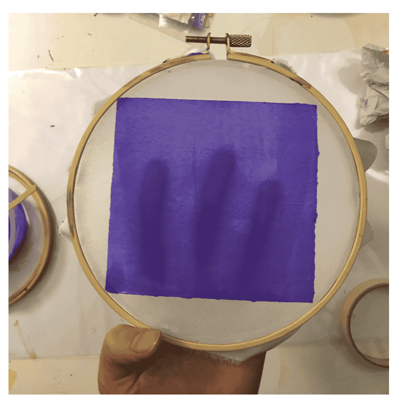
Tests
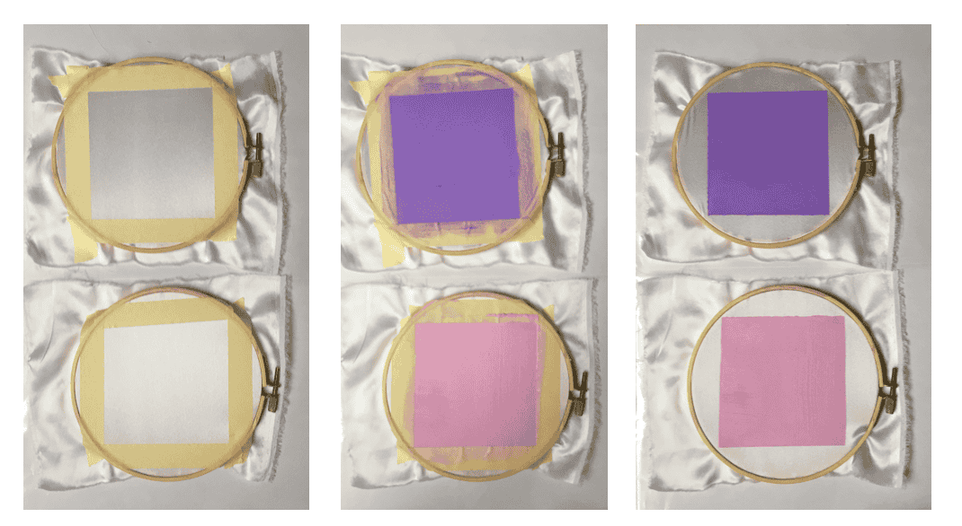 DIY screenprinting = using embroidery hoop, masking tape and a squeegee
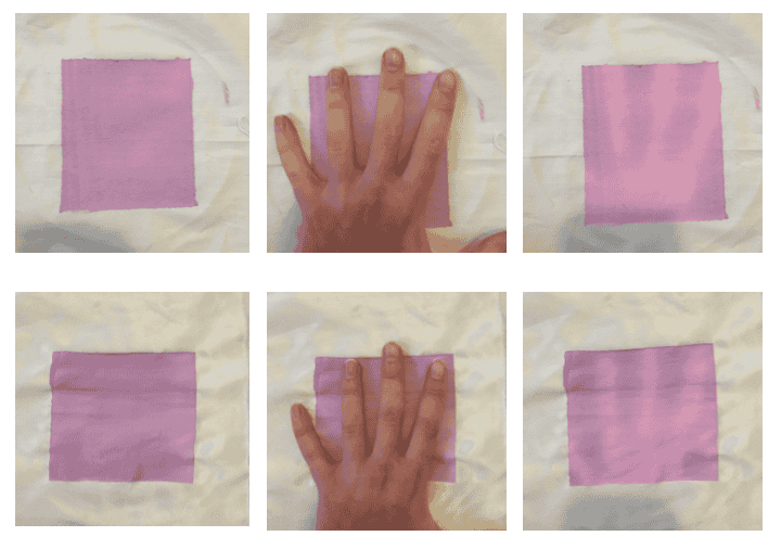 Pink pigment = subtle colour change
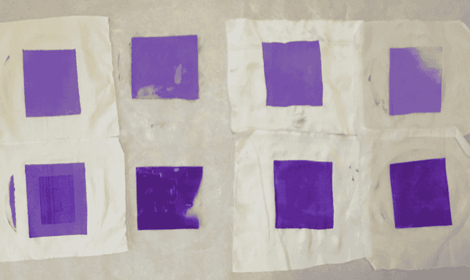
Starting from left to right: (top = paint bottom= binder)
_ 1 Cotton
__ 2 Organza
___ 3 Cotton + Silk
____ 4 Silk + Elastic
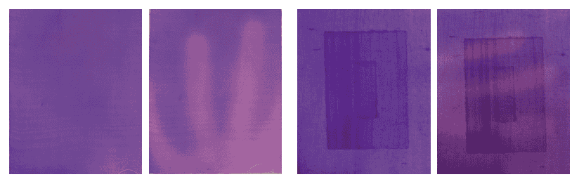
Material = Cotton, Left = Pigment mixed with Acrylic Paint, Right = Pigment mixed with Acrylic Binder
 Material = Organza (synthetic)
Left = Pigment mixed with Acrylic Paint
Right = Pigment mixed with Acrylic Binder
Material = Organza (synthetic)
Left = Pigment mixed with Acrylic Paint
Right = Pigment mixed with Acrylic Binder
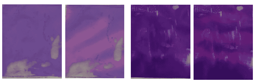
 Material = Cotton + Silk
Left = Pigment mixed with Acrylic Paint
Right = Pigment mixed with Acrylic Binder
Material = Cotton + Silk
Left = Pigment mixed with Acrylic Paint
Right = Pigment mixed with Acrylic Binder
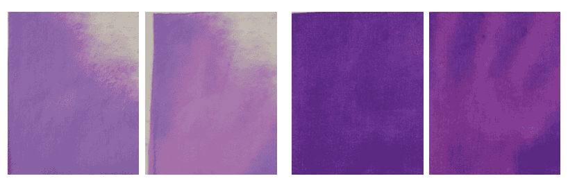
 Material = Silk + Elastic
Left = Pigment mixed with Acrylic Paint
Right = Pigment mixed with Acrylic Binder
Material = Silk + Elastic
Left = Pigment mixed with Acrylic Paint
Right = Pigment mixed with Acrylic Binder
Results
Conclusion
-
Pigments worked MUCH better in colder temperature e.g. outside rather then in a warm room of the room.
Temperature of environment matters. -
Not much difference between different fabrics regarding colour change
-
Some fabrics where easier to screenprint then others: e.g cotton was better then the synthetic organza
-
Acyrlic paint was not as desirable in result = left fabric stiff and the white dulled the thermo pigment
-
Fabric painting meduim (clear) would be ideal I think
-
Interesting to do various tests using various pigment measurements etc.
-
I briefly tried nail polish which had very interesting results, however was less desirable on fabric.
Would be interesting to explore further with this
Thermochromic pigment user guide
S O U N D
Make a Monoamp
Custom Mono Amp for Textile Speakers tutorial from Liza Stark
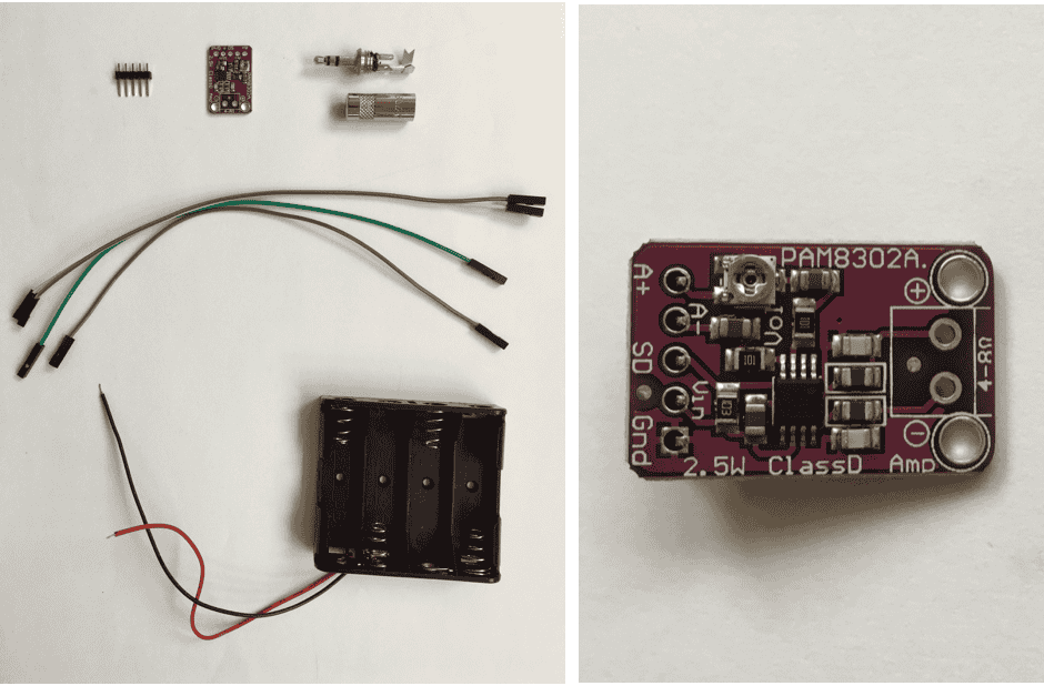
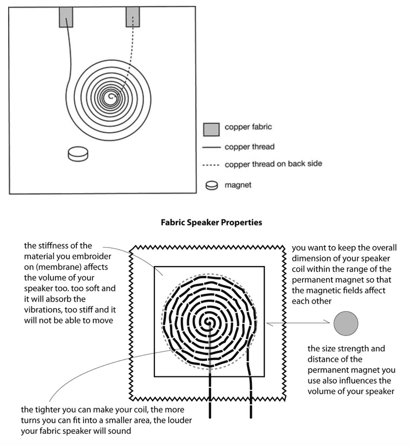
Integrate into textiles with spiraled coil (conductive thread) and leftover thermo cotton fabric
NOTE
-
Different conductive fabrics heat at differently e.g. coated copper coil, doesn't heat much, while the conductive thread does.
-
If it's coated = can touch
-
If it's not coated = can't touch itself
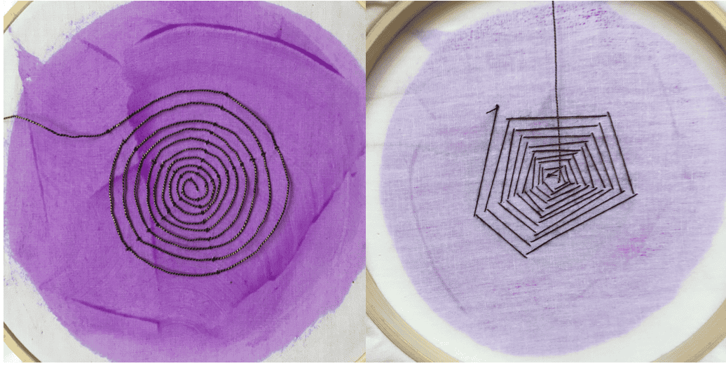 Conductive thread spiraled and couched
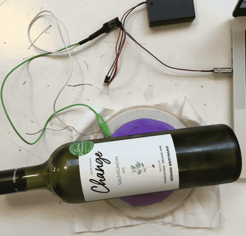 Chilled white wine to darken the thermo fabric
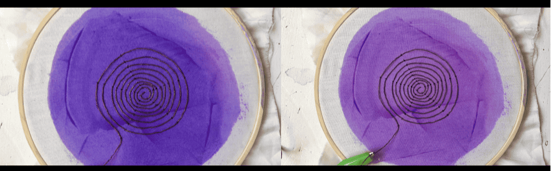 Showing the colour difference of cold -> heat of speaker
THE SPEAKER WORKS !!!
M O T I O N
FLIP DOTS
Power load: flipping wing
Electromagnet
A current through a wire generates an magnetic field
-
Make coil (coated conductive wire if touching) wrap around many times
-
Wrap end pieces to secure it in a circle (leave room at both ends)
-
Burn off enamel + solder the ends (check with mutilmeter if the isolation is gone)
-
Attach circuit using driver circuit transistor, 9V battery and Arduino Uno
-
Code Arduino Uno to make flip + alter code to desired effect
-
Place Magnet under coil
CODE
//Make the coil flip up and down
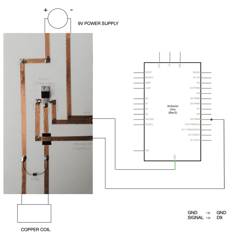
int signal_pin = 3; //define the pin where the Arduino pin (signal) is connected
void setup() {
pinMode(signal_pin, OUTPUT); //define pin of the Led as an output
//pinMode(pin, OUTPUT);
//pinMode(pin, INPUT);
//pinMode(pin, INPUT_PULLUP);
}
void loop() {
digitalWrite(signal_pin, HIGH); //turn the Led on
//digitalWrite(pin, HIGH/LOW);
//HIGH -> 5V
//LOW -> 0V ground
delay(1000); //wait 1000millisecond
digitalWrite(led_pin, LOW); //turn off
delay(1000); //wait 1000millisecond
}
Can change the delay(1000) to make the flip faster or slower
Flip dot using Copper Coil, Magnet, Transistor Driver Circuit and Arduino Uno:
I like the idea of attching something on top of the coil to make it 'pop'
Using a leftover laser cut eye from week03 I sewed the pupil and iris loosly to see if the coil would make them jump out.
RESULT
-
It does not work as well as I would like. I would like to experiment further with this in the future.
Pleats/ mini hinges might work better? -
I would also like to experiment with geometrically cut shapes to see how they might move with the flip dot.
NOTE
-
Change the orientation of magnet if movement is little
-
Improve movement: size of coil, number of wraps, changing the magnet
-
A lot of experimenting
-
Can connect input device to circuit and control power load through sensor
-
Can use 5V pin of Arduino as power source
C O N C L U S I O N
Prepare for a lot of: Computer says no
Isolate the problem -> figure out solution step by step
Time goes by very quickly when doing electronics (I'm still not sure if it's in a good or bad way)
F U T U R E
I would like to explore further:
-
Optic fibers + NeoPixels with sequenced light to look like muscle fibers, programed by ATtiny and embedded neatly into fabric to make an Anatomical Corset
-
Experiment further with added Analog sensors and make it more interactive
-
Experiment further with magnets, the magnetic field and sound
-
Nipple coils that pop !!!