8. Wearables
Research
weekly assignment
Check out the weekly assignment here or login to your NuEval progress and evaluation page.
get inspired!
Check out and research alumni pages to betetr understand h ow to document and get inspired
- Emma Shannon
- Elena Rotaru
- Diane Wakim Le TextileLab Lyon 2020-21_
- Vicky Luan
- Loes Bogers TextileLab Amsterdam 2019-20_
- Sara Alvarez TextileLab Amsterdam 2020-21_
- Kate Reed
Wearables Notes
References & Inspiration
Tools
Lesson with Gerard:
Capacitive sensor:
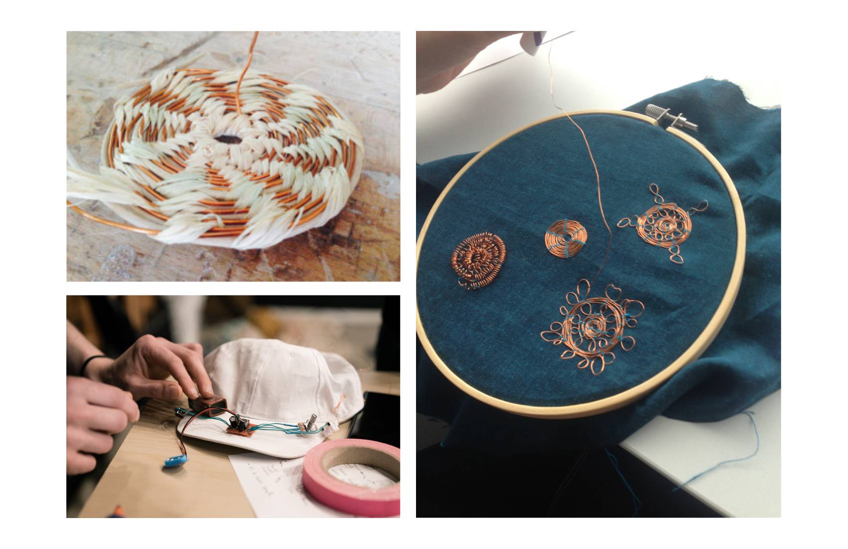
To start the lesson with Gerard this week, we made a capacitive sensor, which is ‘a technology, based on capacitive coupling, that can detect and measure anything that is conductive or has a dielectric constant different from air’. These sensors can measure when anything conductive is near them and how close which means they also serve as proximity sensors due to the bodies conductivity. The construction of these sensors was very simple, it required us to connect anything conductive to a resistor and the XIAO/Arduino.
The code we needed for it to read how close we were, was:
#include <CapacitiveSensor.h>

CapacitiveSensor   cs_4_2 = CapacitiveSensor(4,2);        // 10M resistor between pins 4 & 2, pin 2 is sensor pin, add a wire and or foil if desired

void setup() {
   Serial.begin(115200);
}

void loop() {

    long sensor =  cs_4_2.capacitiveSensor(30);
//     Serial.println(sensor);

    if (sensor > 2250) {
        Serial.println("Touching!!!");
    } else {
        Serial.println("Nothing there!!!");
    }

    delay(10);
}
We experimented with a few different materials for the sensor including hardware like screws and conductive biomaterials. All of these were successful and gave us a range of reading when someone moved their hand closer and further away from them.
VIDEOS
LED strips:
After this, we spent the rest of the lesson programming LED strips. These are sold in long strips of a few meters but can be cut at any length as they have connection points for the circuit either between every pixel or every 3 in some cases. They also come in a range of pixel densities and colour options. We used the WS2813 RGB strips for this lesson for more info you can find the data sheets for The connections we used to link the led strip to the XIAO are below.

We had to download the Adafruit Neopixel, and Adafruit DMA Neopixel libraries to allow us to program them in Arduino. Initially, we tested them by programming the pixels to turn on one by one along the strip using this code
#include <Adafruit_NeoPixel.h>

#define LED_PIN    12
#define LED_COUNT 20

Adafruit_NeoPixel strip(LED_COUNT, LED_PIN, NEO_GRB + NEO_KHZ800);

void setup() {
  strip.begin();
  strip.show();
}

void loop() {

  for(int i=0; i<strip.numPixels(); i++) {
    strip.clear();
    strip.setPixelColor(i, 0, 50, 255);
    strip.show();
    delay(20);
  }
}
VIDEO
Then we had a go at changing the colours, I used this site to help with generating the colour codes.
Next, we learnt how to turn on select pixels in the strip. An example code for this is:
void loop() {

  strip.setPixelColor(2, 0, 230, 140);
  strip.show();
  delay(60);
}
where (2, 0,230,140) = the 3rd (N+1) pixel in the strip is set to R0, G230, B140.
Once I got this, I did a few trials with different colour and number combinations and the sequence they turned on in.
==== "Choosing Colours"
void setup(){
    strip.begin();
    strip.show();
}

void loop() {

  strip.setPixelColor(2, 0, 230, 140);
  strip.show();
  delay(60);

  strip.setPixelColor(8, 100, 30, 140);
  strip.show();
  delay(60);
}
==== "Multicoloured"
#include <Adafruit_NeoPixel.h>

#define LED_PIN 2
#define LED_COUNT 12

Adafruit_NeoPixel strip(LED_COUNT, LED_PIN, NEO_GRB + NEO_KHZ800);

void setup() {
  strip.begin();
  strip.show();
}

void loop() {

  strip.setPixelColor(0, 60, 230, 50);
  strip.setPixelColor(1, 90, 130, 140);
  strip.setPixelColor(2, 0, 230, 140);
  strip.setPixelColor(3, 120, 30, 240);
  strip.setPixelColor(4, 230, 30, 70);
  strip.setPixelColor(5, 240, 10, 40);
  strip.setPixelColor(6, 30, 230, 90);
  strip.setPixelColor(7, 70, 40, 140);
  strip.setPixelColor(8, 100, 30, 140);
  strip.setPixelColor(9, 90, 230, 20);
  strip.setPixelColor(10, 160, 230, 140);
  strip.setPixelColor(11, 80, 180, 10);

  strip.show();
  delay(60);
}
==== "Multicoloured Sequence"
#include <Adafruit_NeoPixel.h>

#define LED_PIN 2
#define LED_COUNT 12

Adafruit_NeoPixel strip(LED_COUNT, LED_PIN, NEO_GRB + NEO_KHZ800);

void setup() {
  strip.begin();
  strip.show();
}

void loop() {

  strip.setPixelColor(0, 60, 230, 50);
  strip.setPixelColor(1, 90, 130, 140);
  strip.setPixelColor(2, 0, 230, 140);
  strip.setPixelColor(3, 120, 30, 240);
  strip.setPixelColor(4, 230, 30, 70);
  strip.setPixelColor(5, 240, 10, 40);
  strip.setPixelColor(6, 30, 230, 90);
  strip.setPixelColor(7, 70, 40, 140);
  strip.setPixelColor(8, 100, 30, 140);
  strip.setPixelColor(9, 90, 230, 20);
  strip.setPixelColor(10, 160, 230, 140);
  strip.setPixelColor(11, 80, 180, 10);

  strip.show();
  delay(60);
  strip.clear();
  delay(60);
}
I also had a look at the strandtest_wheel example from the Adafruit Neopixel library that ran a very long cycle of a range of different lighting patterns and flows. I really liked the gradual rainbow cycle so I tried to isolate this bit of the code to get it to do just that bit. I couldn’t work out which bit of the code it was so I tried a few different selections but in the end, I just had to delete a few lines from the start of the code and it worked.
CODE
#include <Adafruit_NeoPixel.h>
#ifdef __AVR__
 #include <avr/power.h>
 #endif
 #define PIN 2

 // Parameter 1 = number of pixels in strip
 // Parameter 2 = Arduino pin number (most are valid)
 // Parameter 3 = pixel type flags, add together as needed:
 //   NEO_KHZ800  800 KHz bitstream (most NeoPixel products w/WS2812 LEDs)
 //   NEO_KHZ400  400 KHz (classic 'v1' (not v2) FLORA pixels, WS2811 drivers)
 //   NEO_GRB     Pixels are wired for GRB bitstream (most NeoPixel products)
 //   NEO_RGB     Pixels are wired for RGB bitstream (v1 FLORA pixels, not v2)
 //   NEO_RGBW    Pixels are wired for RGBW bitstream (NeoPixel RGBW products)
 Adafruit_NeoPixel strip = Adafruit_NeoPixel(60, PIN, NEO_GRB + NEO_KHZ800);

 // IMPORTANT: To reduce NeoPixel burnout risk, add 1000 uF capacitor across
 // pixel power leads, add 300 - 500 Ohm resistor on first pixel's data input
 // and minimize distance between Arduino and first pixel.  Avoid connecting
 // on a live circuit...if you must, connect GND first.

 void setup() {
   // This is for Trinket 5V 16MHz, you can remove these three lines if you are not using a Trinket
   #if defined (__AVR_ATtiny85__)
     if (F_CPU == 16000000) clock_prescale_set(clock_div_1);
   #endif
   // End of trinket special code

   strip.begin();
   strip.setBrightness(50);
   strip.show(); // Initialize all pixels to 'off'
 }

 void loop() {

   rainbow(20);
   rainbowCycle(20);
   // theaterChaseRainbow(50);
 }

 // Fill the dots one after the other with a color
 void colorWipe(uint32_t c, uint8_t wait) {
   for(uint16_t i=0; i<strip.numPixels(); i++) {
     strip.setPixelColor(i, c);
     strip.show();
     delay(wait);
   }
 }

 void rainbow(uint8_t wait) {
   uint16_t i, j;

   for(j=0; j<256; j++) {
     for(i=0; i<strip.numPixels(); i++) {
       strip.setPixelColor(i, Wheel((i+j) & 255));
     }
     strip.show();
     delay(wait);
   }
 }

 // Slightly different, this makes the rainbow equally distributed throughout
 void rainbowCycle(uint8_t wait) {
   uint16_t i, j;

   for(j=0; j<256*5; j++) { // 5 cycles of all colors on wheel
     for(i=0; i< strip.numPixels(); i++) {
       strip.setPixelColor(i, Wheel(((i * 256 / strip.numPixels()) + j) & 255));
     }
     strip.show();
     delay(wait);
   }
 }

 //Theatre-style crawling lights.
 void theaterChase(uint32_t c, uint8_t wait) {
   for (int j=0; j<10; j++) {  //do 10 cycles of chasing
     for (int q=0; q < 3; q++) {
       for (uint16_t i=0; i < strip.numPixels(); i=i+3) {
         strip.setPixelColor(i+q, c);    //turn every third pixel on
       }
       strip.show();

       delay(wait);

       for (uint16_t i=0; i < strip.numPixels(); i=i+3) {
         strip.setPixelColor(i+q, 0);        //turn every third pixel off
       }
     }
   }
 }

 //Theatre-style crawling lights with rainbow effect
 void theaterChaseRainbow(uint8_t wait) {
   for (int j=0; j < 256; j++) {     // cycle all 256 colors in the wheel
     for (int q=0; q < 3; q++) {
       for (uint16_t i=0; i < strip.numPixels(); i=i+3) {
         strip.setPixelColor(i+q, Wheel( (i+j) % 255));    //turn every third pixel on
       }
       strip.show();

       delay(wait);

       for (uint16_t i=0; i < strip.numPixels(); i=i+3) {
         strip.setPixelColor(i+q, 0);        //turn every third pixel off
       }
     }
   }
 }

 // Input a value 0 to 255 to get a color value.
 // The colours are a transition r - g - b - back to r.
 uint32_t Wheel(byte WheelPos) {
   WheelPos = 255 - WheelPos;
   if(WheelPos < 85) {
     return strip.Color(255 - WheelPos * 3, 0, WheelPos * 3);
   }
   if(WheelPos < 170) {
     WheelPos -= 85;
     return strip.Color(0, WheelPos * 3, 255 - WheelPos * 3);
   }
   WheelPos -= 170;
   return strip.Color(WheelPos * 3, 255 - WheelPos * 3, 0);
 }
Soldering:
The connections between the wires on the end of my led strip and the strip itself were very faulty and it had been messing up my tests. To fix this, Gerard showed us how to remove and re-solder the joints. This was quite difficult as the connections were very small so we had to be very precise with it.

LESSON WITH CIT:
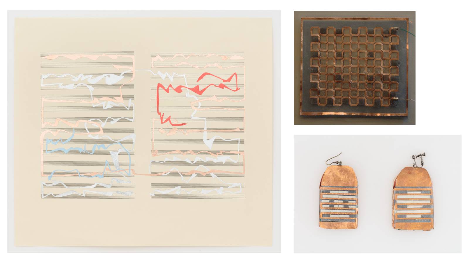
In the lesson with CIt, we were trialling thermochromic ink - a type of ink that changes colour with heat - which I was really excited about as this was one of the main things from the lecture that I wanted to sample. In the lab we had a thermochromic pigment so we had to mix it with transparent screen printing ink to use it as a paint. To test out the different possibilities of the pigment we mixed it with 3 different strengths of the screen printing ink and printed some samples of all of these. We did the quantities of this by eye depending on the colour we wanted, I think we probably could have started at a slightly darker colour as when the lightest ones had dried they were very pale which meant they didn’t have much room to change.

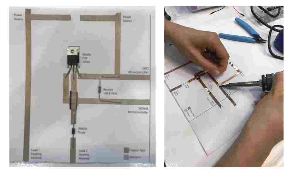
While the samples were drying, we made a paper circuit using Liza Strak’s example for a heating component??. This used a Mosfet FQP 30N06L which I hadn’t used before but that we programmed later to act like a switch so the current wasn’t constantly heating up the textile sample later. Most of the group made this circuit with cooper tape so they had to solder the joints and between the tape and where it joined other components as the sticky side of copper tape isn’t conductive. I used conductive nylon tape which is conductive on both sides so I was ok to just use the tape as is.
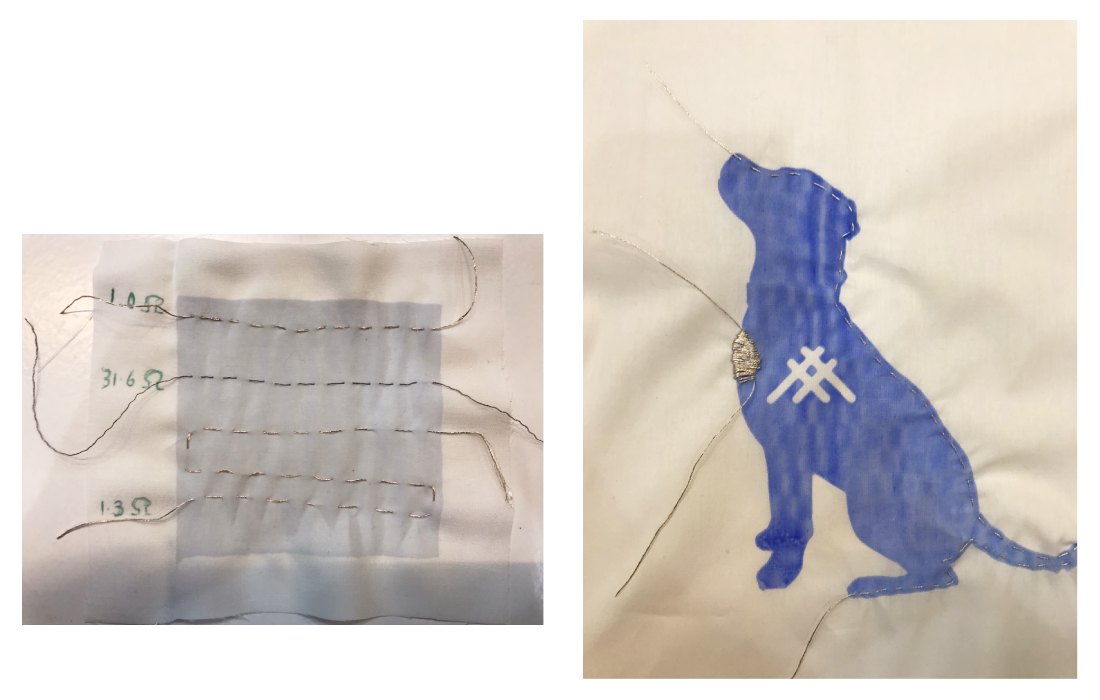
Next I made a few different stitch samples using the conductive thread. I used a sample of the weakest pigment mix and did three basic running stitch sample, two in the copper thread of different lengths and one in the stretch conductive thread. Then I used a sample of the darker pigment mix and did a long running stitch round the sample and a short satin stich to see how this would change the effect. I measured the resistances on all of these samples so I could alter the code later appropriately.
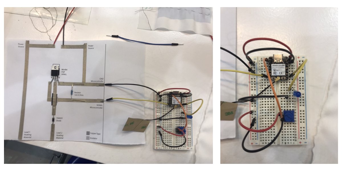
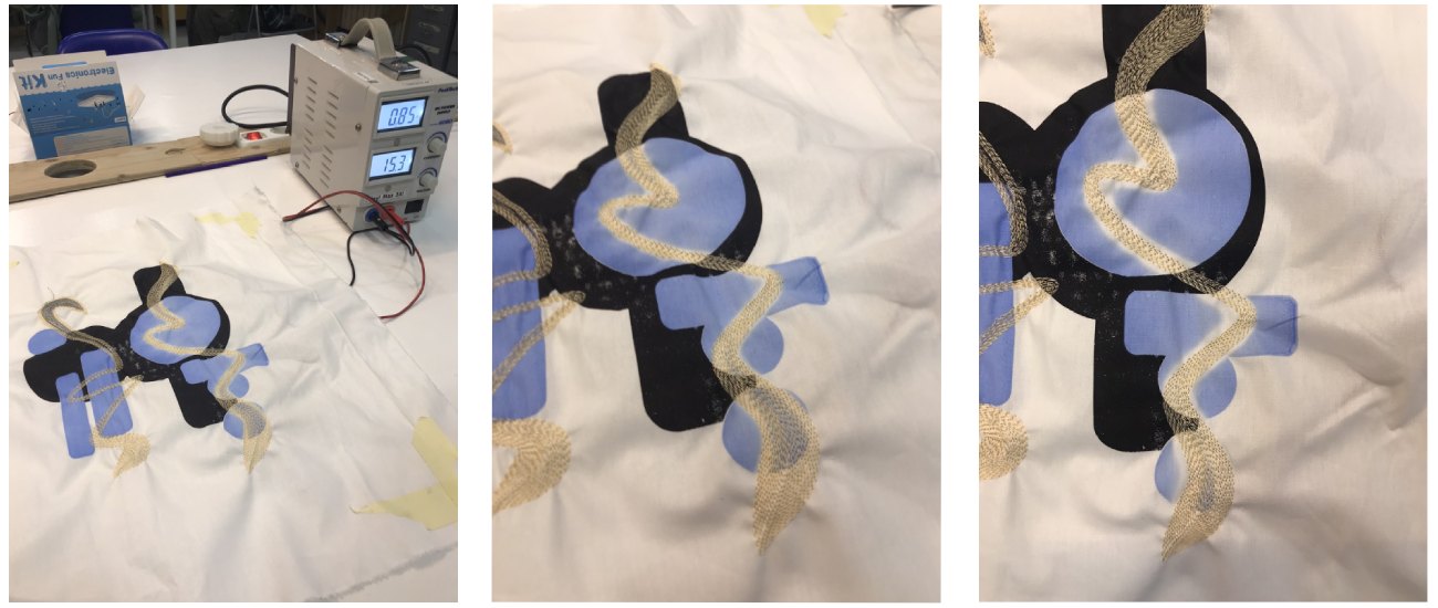
To finish the circuit, we needed to join a better to the paper circuit, then join this to the XIAO and add a potentiometer to control the current. We also added a LED but this was extra. Finally, we used alligator clips to join the thread in the textile samples.
We used a sample Cit brought with her first to check it all worked, this one used a very dark pigment mix so the colour change was very pronounced. It also went transparent very quickly and took quite a while to turn back to blue.
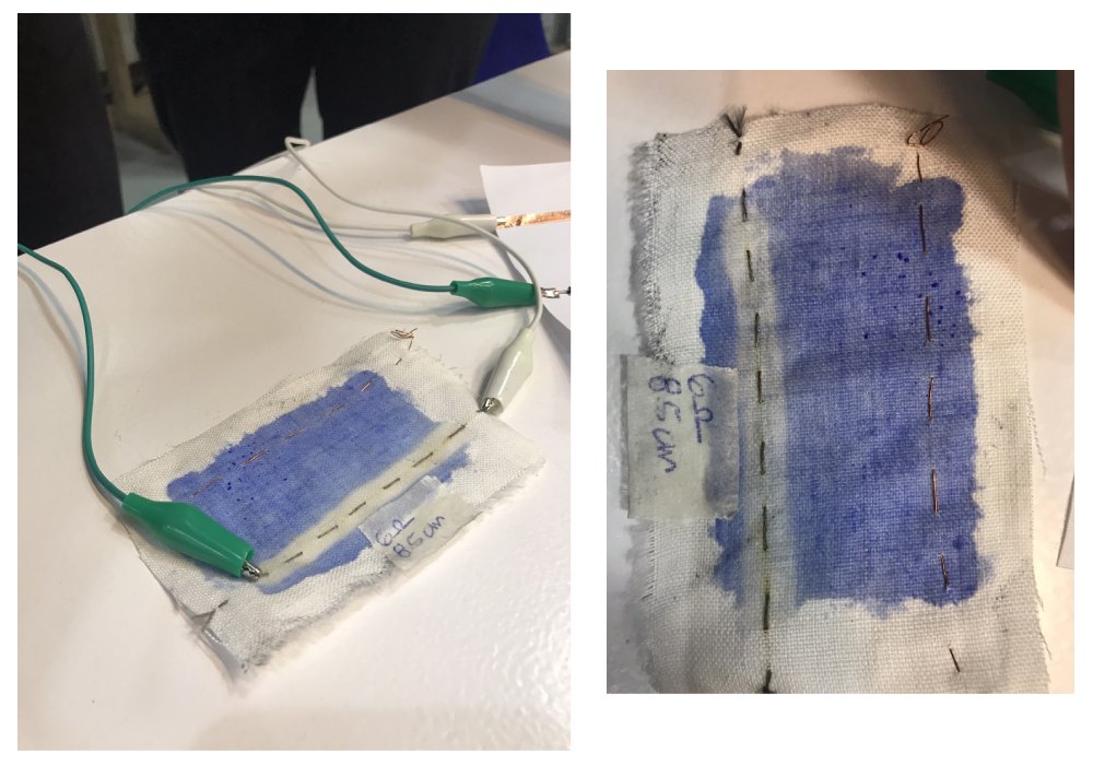
It also worked well on the samples we had painted earlier but obviously a lot less clear on the lighter ones. The light samples I did with the copper thread did not show up very well at all but the other 3 did, especially the satin stich.

Shape Memory Alloy:
We didn’t have the time or materials to make our own samples with the SMA wires but Cit did show us some examples of it so we got an idea of how it worked. It required quite specific tensions to pull the fabric in the way that we wanted it to so it had to be help very tight.
VIDEO
Process and workflow
Screen Printing:
I wanted to focus on the thermochromic ink this week and try to really understand how it worked and how much control you could have over the change in the colour. To do this, I wanted to make a range of samples from the same base print to see how differently I could get them to change based on how I ran the current through them.
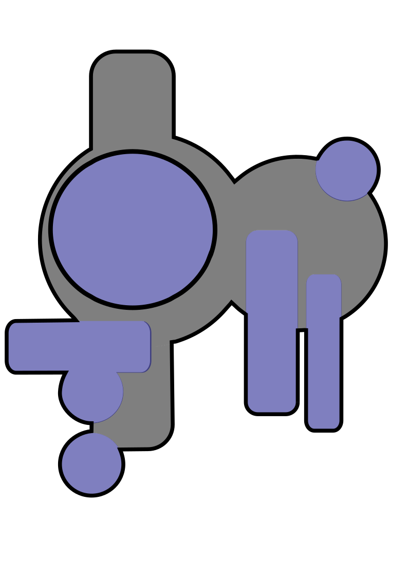
I made a 2-colour graphic in Inkscape that I would print half in normal ink and half in thermochromic. For the stickers for the silk screens, I needed to import the 2 separated layers into rhino so that I could cut them out with the vinyl cutter. I transferred these onto 2 of the silk screens we had that were the same size, making sure to line them up well to help with matching up the prints later.
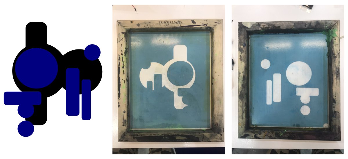
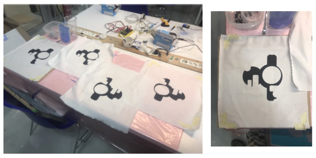
I then printed 4 of these doing the normal black layer first then the thermos blue one when it was dry. I have done quite a lot of screen printing before so I was quite happy with how these turned out.
EMBROIDERY SOFTWARE:
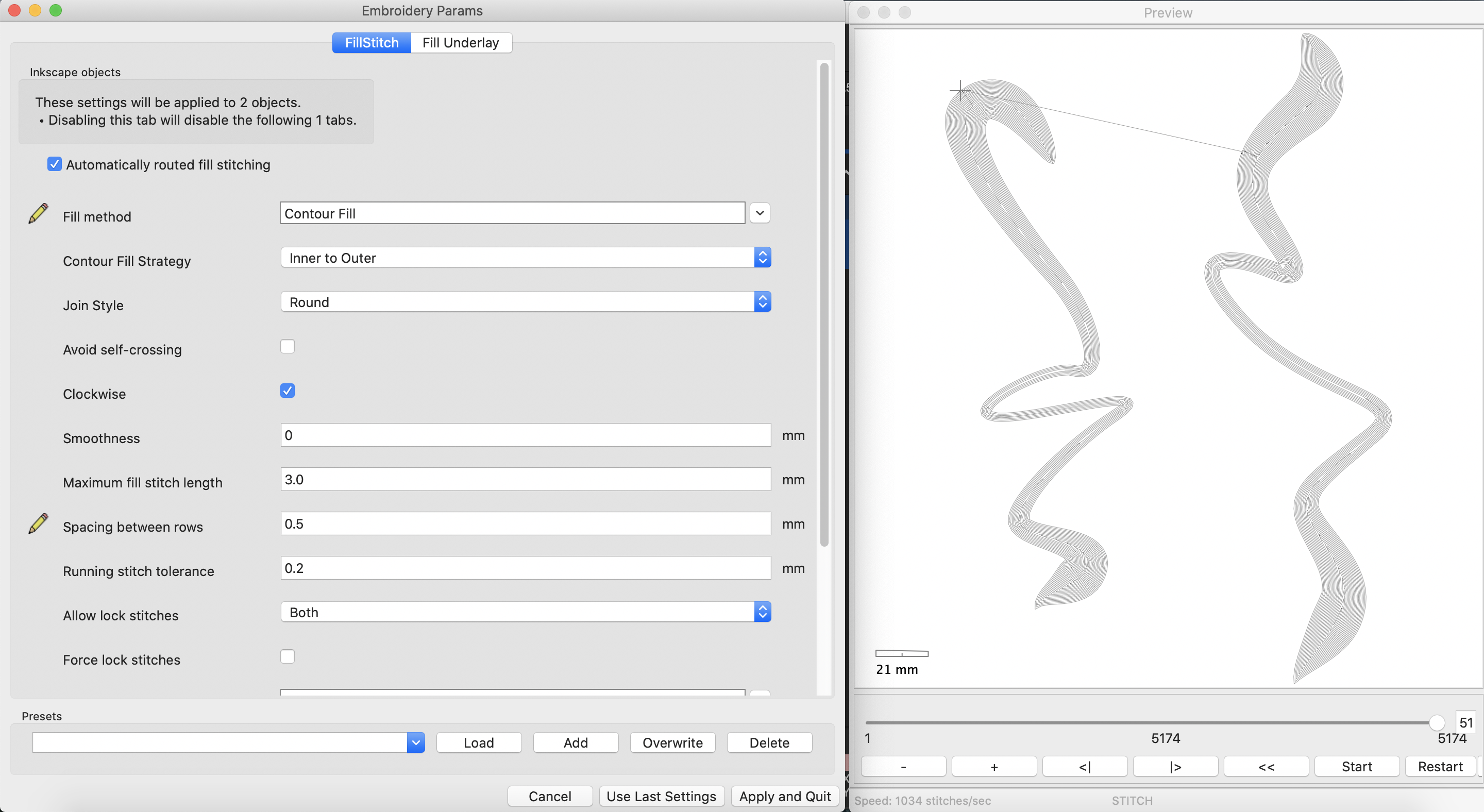
Next I needed to add something to the prints to allow a current to go through them. I designed 3 different embroidery pattern for this on Inkscape and converted them from vector paths to stitch patterns using the plug in Ink/Stitch.
I hadn’t used the digital embroidery machine before so we did a few tests first to get the settings right using the thinner conductive thread that we had in the lab.
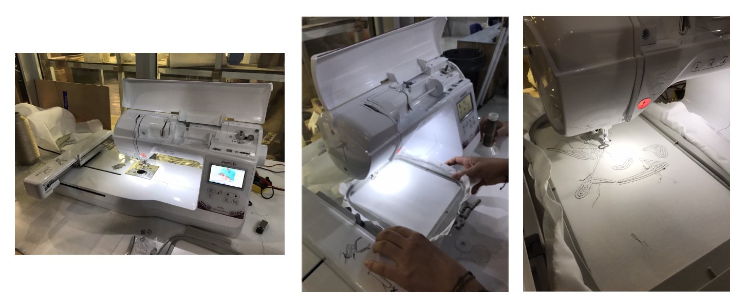
In the end, it worked best with a normal thread on top and the conductive one just in the bobbin as it kept snapping when we tried to use it in both sides.
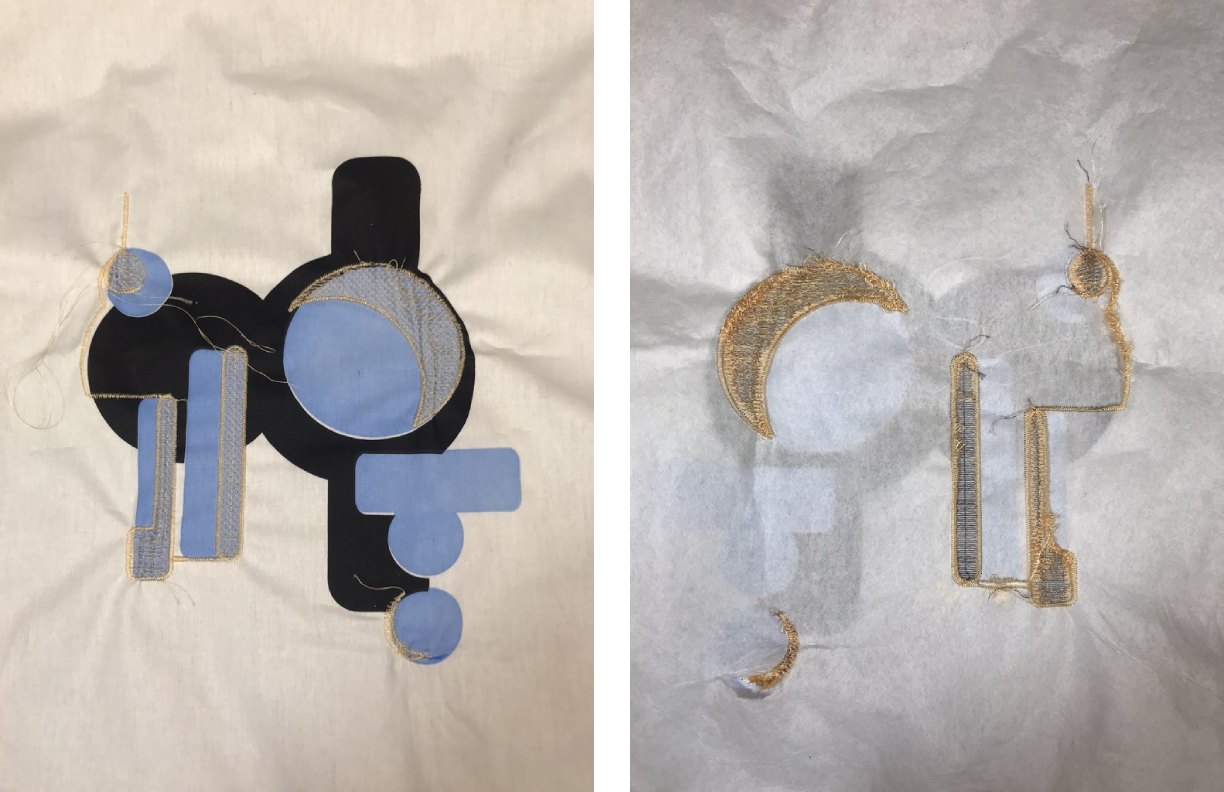
The print I had done was too big for the embroidery frame in one go so I had to break up the patterns I wanted to stitch into 2 half and try to join them by eye when calibrating the machine to start the second pattern. Also it was quite difficult to perfectly align the stitch pattern with the print underneath but I could get pretty close. I managed to successfully embroider 2 of the patterns I wanted before the machine started playing up a lot.
Sample 1: Vector path / intended design:
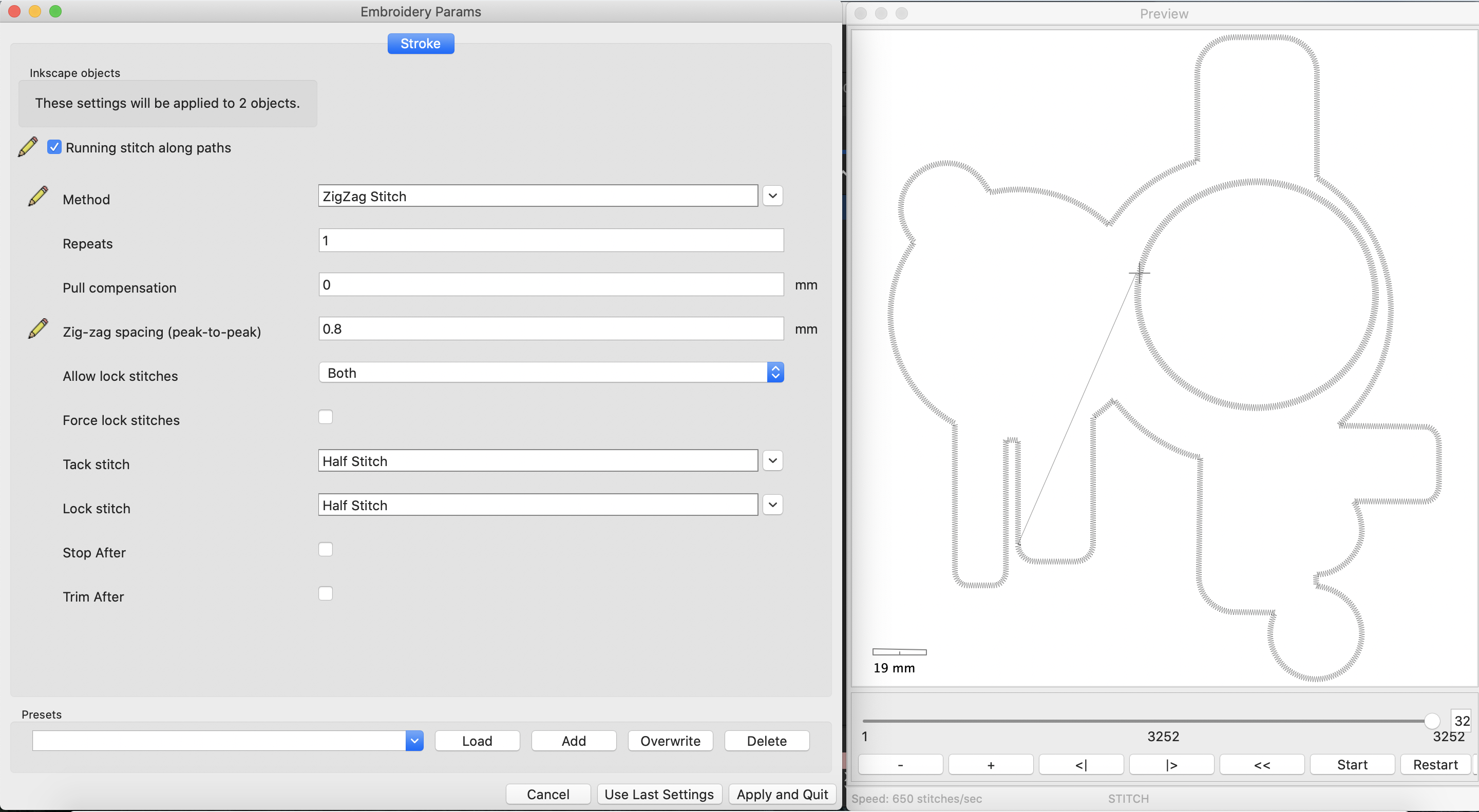
Ink/Stitch parameters:
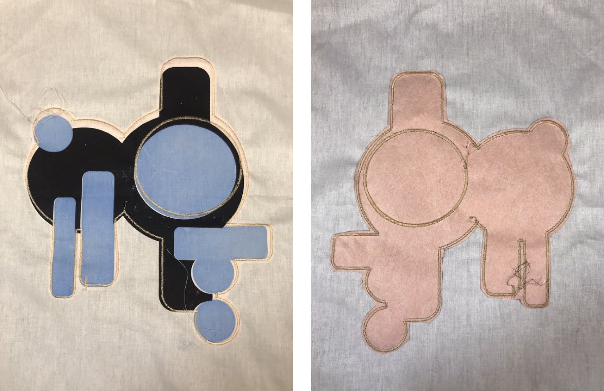
Outcome:
This one was the easiest to embroider as it didn’t really follow the shape of the print that much so it didn’t need to be aligned so closely. I stated the stitching with the conductive thread on the top too but it snapped too many times so I changed to a normal thread.
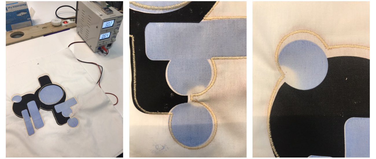
Testing:
Sample 2:
Vector path / intended design:
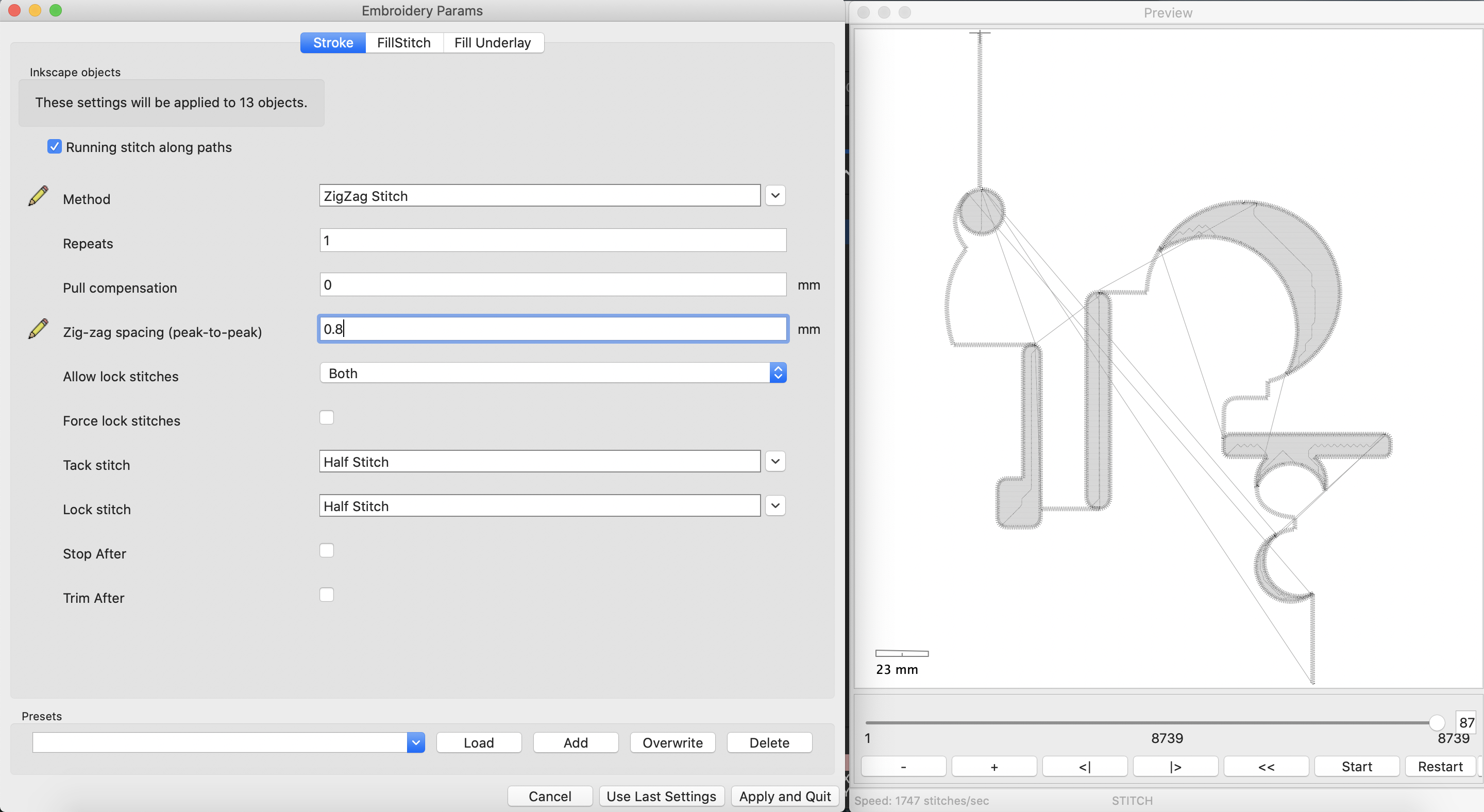
Ink/Stitch parameters:
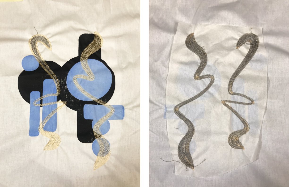
Outcome:
While this one isn’t perfectly aligned, I do think it was still quite successful and looks good. I added a layer of conductive fabric between the cotton and the interfacing for this sample to see how that affects how to current goes through the print.
Testing:
Sample 3:
Vector path / intended design:

Ink/Stitch parameters:
Outcome:
This one was when the machine started playing up so I didn’t manage to finish the embroidery.
Testing:
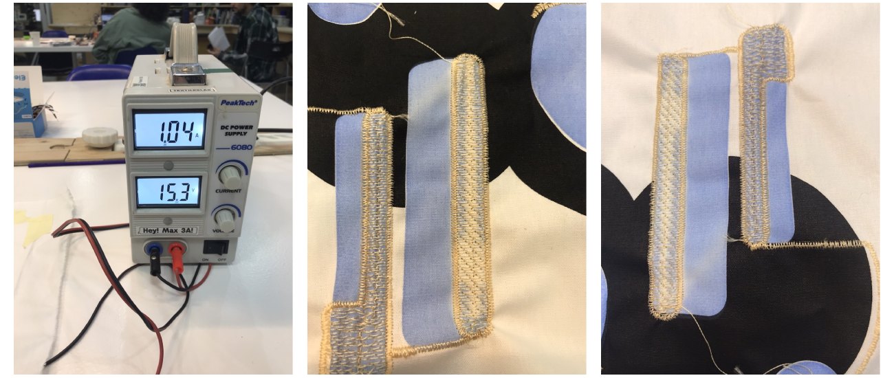
New Samples:
The main reason i think that these samples didnt work is because I used the wrong thread, it has a very high resitance and so isnt getting very hot. To test this, I ran a current through a stitching sample I had made with a different conductive tread and held this on top of theremochromic ink. This thread got quite hot quickly and this transfered to an imprint of the stitching on the ink.
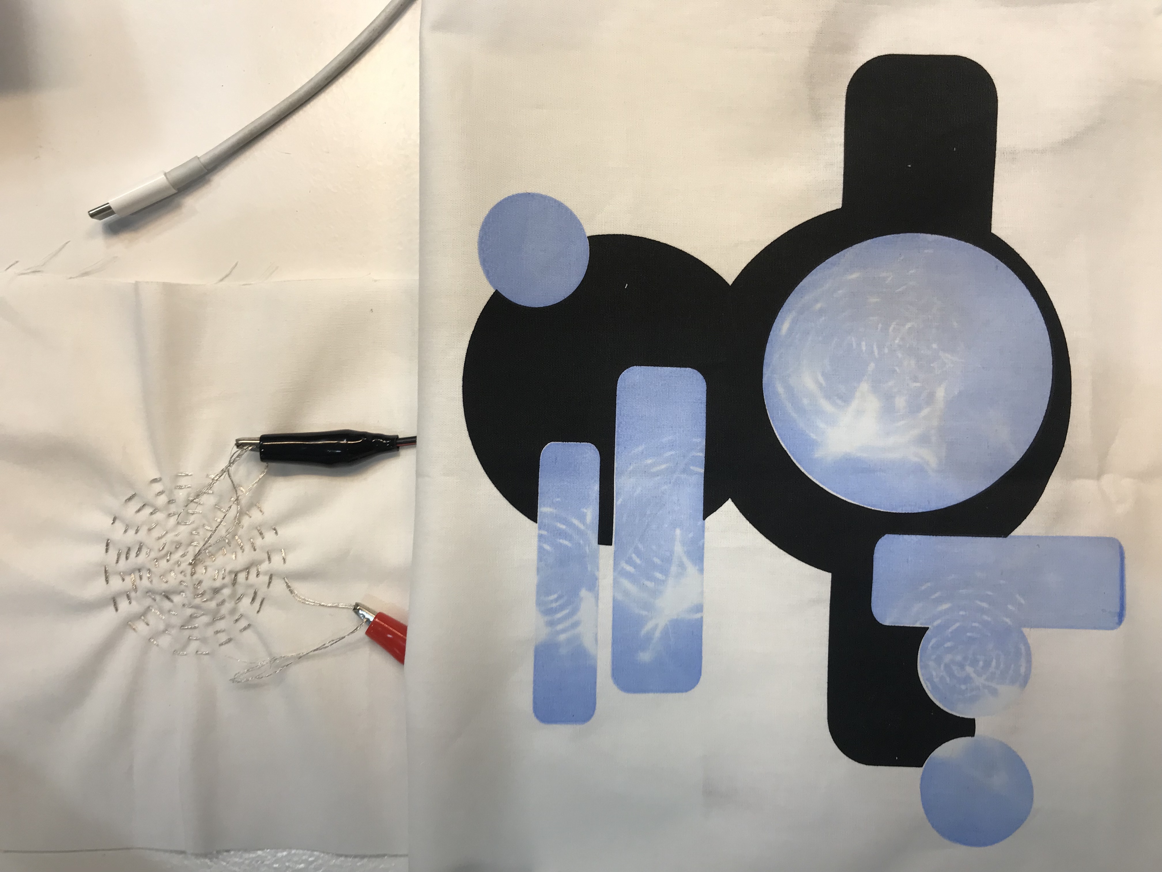
This better conductive thread was a lot thicker than the one I had been using and therefore did not work in the embroidery machine. Instead, I did some manual embroidery using the sewing machine with the conductive thread in the bobbin. When attatched to the power source, this thread quickly caused the desired reaction from the thermochromic ink surrounding it.

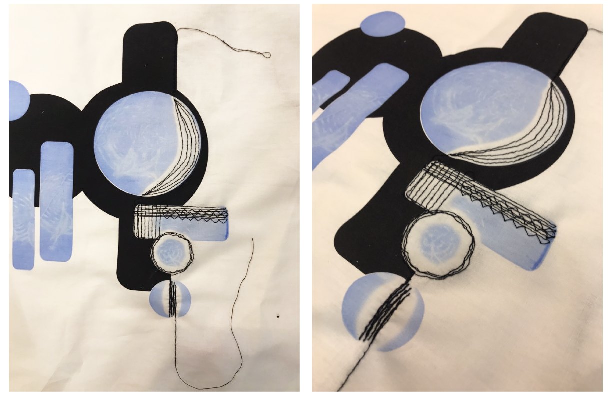
The final input and outputs for my wearable this week were:
| INPUT | OUTPUT |
| Heat from the current running through the conductive thread | Colour change of the thermocromic ink from blue to transparent |
Fabrication Files:
All fabrication files uploaded here: Stitching Files