12. SKIN ELECTRONICS#
Inspiration#

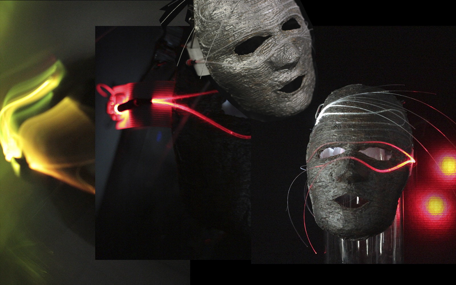
For this assignment I decided to work on my version of the “Skin masquerade party” project, inspired by scenes from the film “Eyes Wide Shut” by Stanley Kubrick where the masks play a major role in the costumes of the same. My idea was to take this concept to a contemporary-futuristic aesthetic, where the mask fulfilled the function of hiding the identity, adaptable to any face, but mainly that the addition of electronic devices was protagonist. After evaluating the different alternatives in terms of the electronic elements that could be applied and generating striking visual effects, I decided to work with Fiber Optics, since I found their characteristics interesting in terms of their morphological versatility and light conductivity. Also in previous investigations I could appreciate that it is highly used in the costumes of artistic and performance scenes.
Construction of the base mask#
- Latex technique + yarn
The materials to be used are only 2: latex and yarn or wool; which allow to create a flexible piece, adaptable to any face and with a short drying time. Latex: A milky substance composed of resins, alkaloids, etc., obtained from cuts made in the trunk of some trees and certain raw materials, such as rubber and lacquer. Latex coagulates on contact with air.
Due to the characteristics of this material, it had to add some textile element to generate a frame or “support skeleton”. Select wool of natural color and intermediate thickness to accelerate the process.
Step by step:
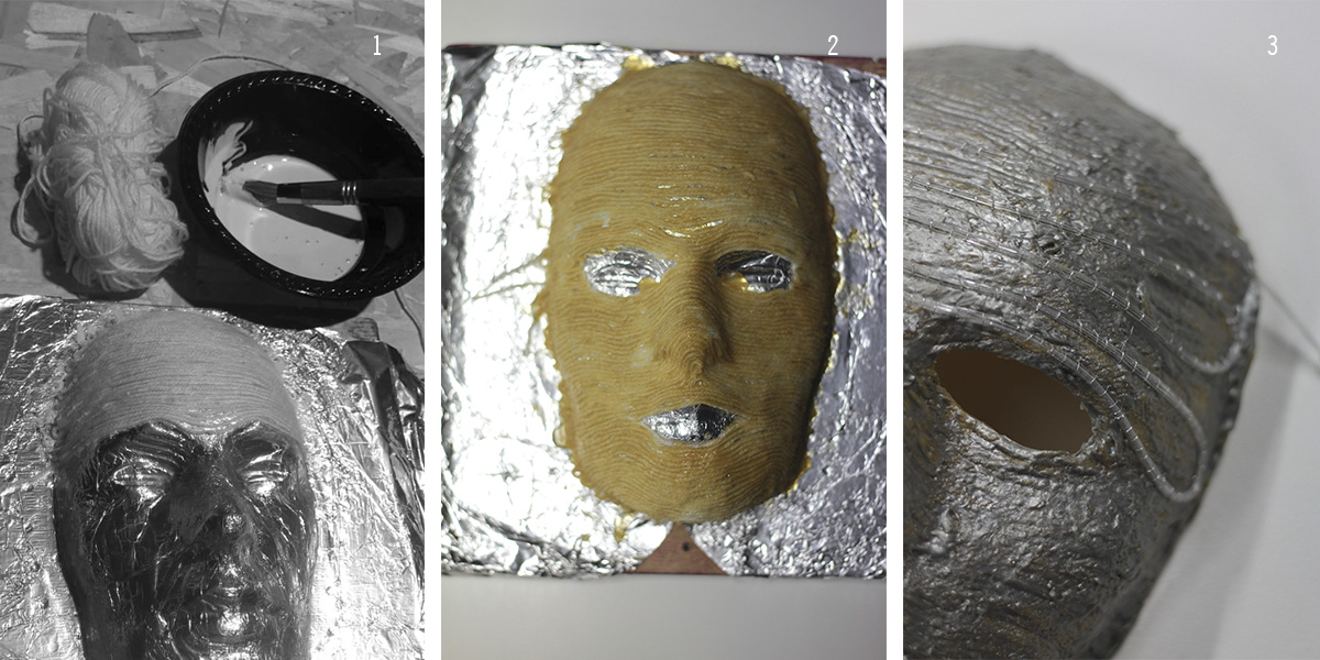
- 1 To make the mask, I used a positive face mold of carved wood with the milling machine. To protect it I covered it with metal paper. First with a brush apply a layer of latex in a horizontal direction and then I was arranging the wire in a continuous zigzag from one end to the other (leaving empty the sectors of eyes and mouth).
- 2 After completing the entire surface, I let the mask dry (approximately 6 hours). As the color of the latex on drying becomes yellowish, I decided to add it to the second layer of silver dye; this time already on a more rigid surface I applied the material with a spatula. At the end of drying, the piece is very easy to remove since it is highly flexible, the edges and surpluses can be trimmed with scissors to achieve a more neat finish.
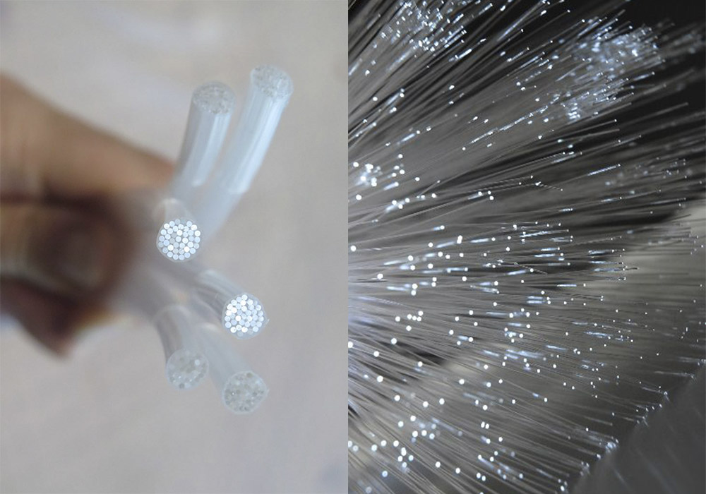
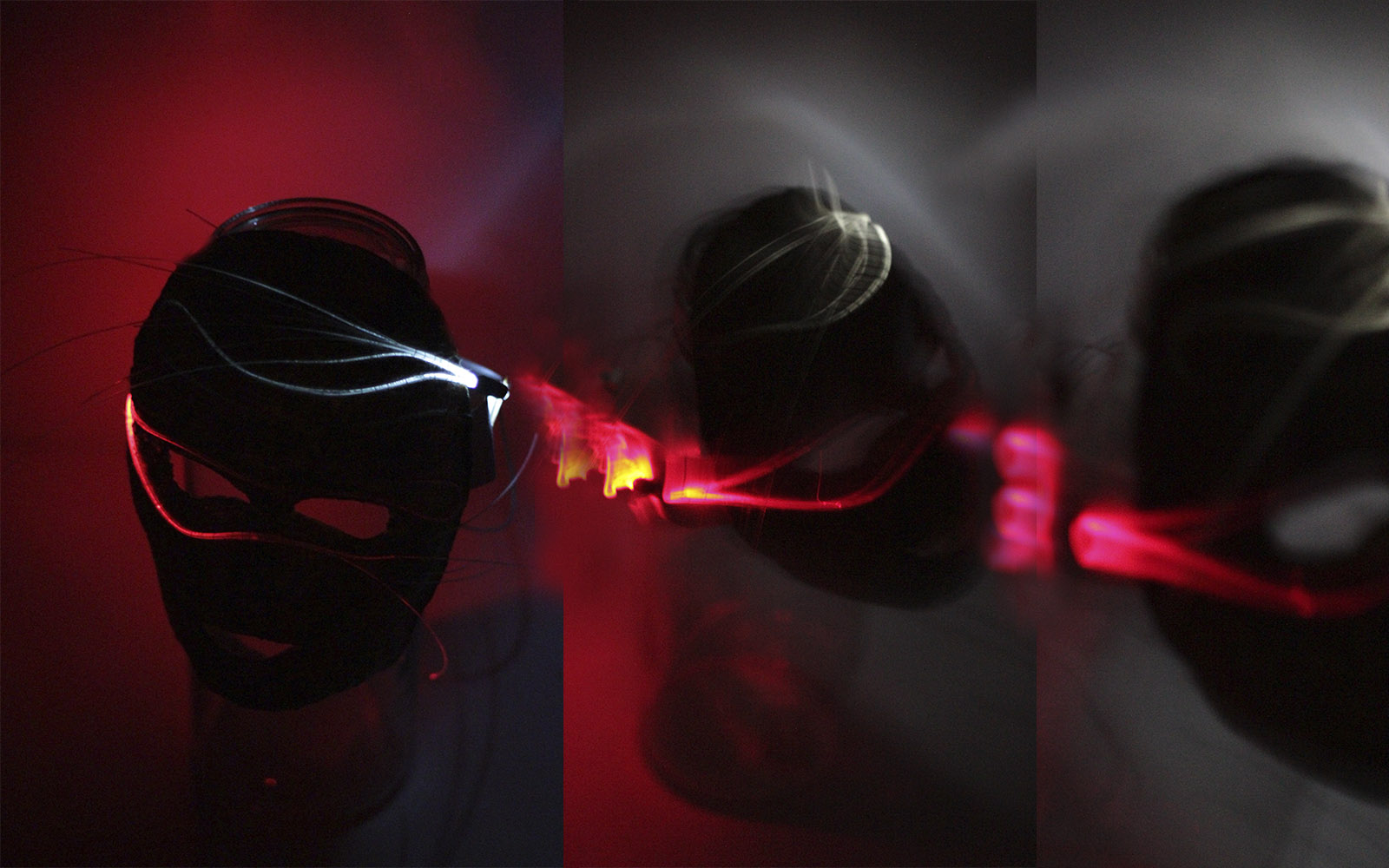
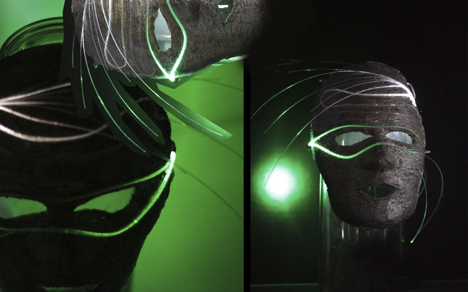
- 3 On the piece already dry and outside the mold, position the fiber optic lines (joining several filaments) in wavy forms, which I was sewing manually to the mask. As the fiber optic used was not of lateral reflectance (ie the light is seen punctually at the ends) “wear” each filament with sandpaper, this generates that these porous areas are illuminated in all its path.
Materials used#
To know more about them and their compositions
- Liquid latex: The natural latex is a colloidal aqueous suspension composed of some fats, waxes and various rubbery resins obtained from the cytoplasm of the laticiferous cells present in some angiosperm and fungi plants.It is frequently white, although it can also present orange, reddish or yellowish tones depending on the species, and milky appearance.
- The heat shrinkable tube: it is a film, with different shapes and sizes, which when subjected to a heat source retracts up to about 50% of the initial size, with great adhesion to the object around which it is wrapped. After cooling down, the film retains its new form. Retractable tubes can be made of polyethylene, PTFE, PVDF, PVC, neoprene, silicone elastomer or Viton.2
About Fiber Optics#
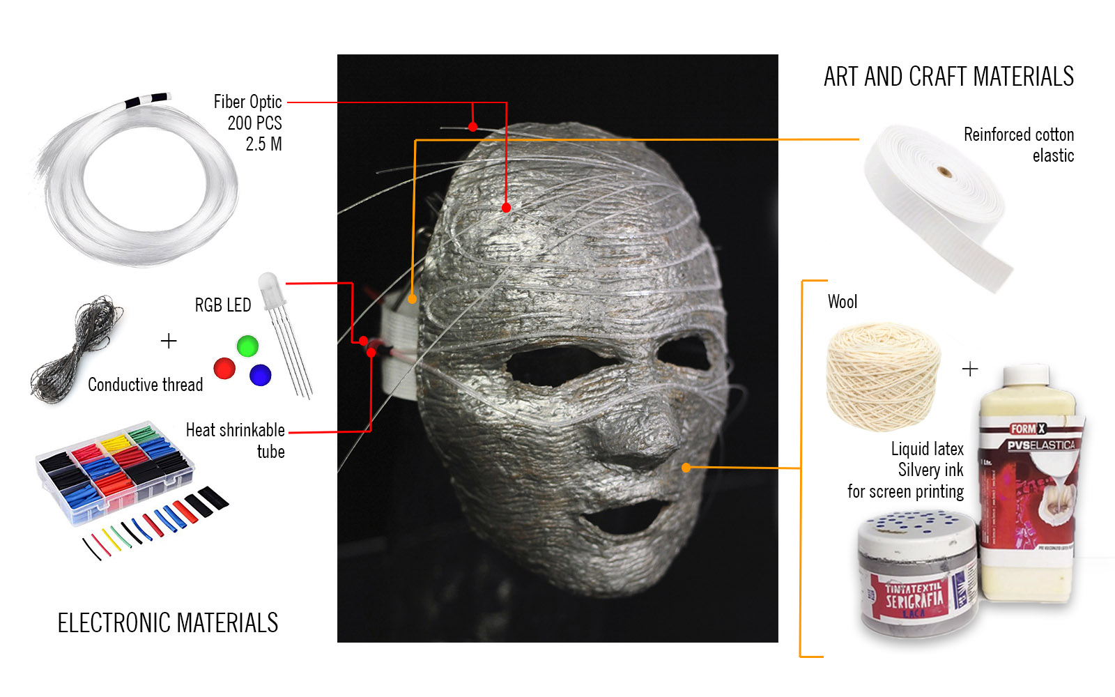
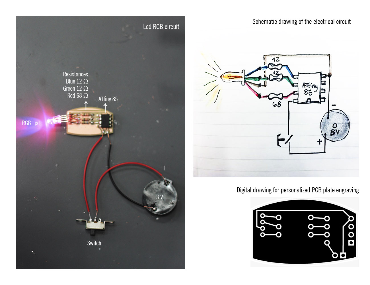
Fiber optic is currently the most advanced medium for the transmission of information through the reflection of light. One of its advantages is the transmission of light of any color without electricity and without heat, which makes it a possible tool to use in wearables. When combined with a light source RGB Led offers a traveling light pattern of scaled combinations between the colors Red, green and blue that fused with the metal surface of the mask generates an aesthetic permeated by technology. To take advantage of the LED luminescence, it is necessary to “encapsulate” the beam of light; for this I used a special piza (printed in 3D) that connects directly and perpendicularly the beam of light with the optical fiber.
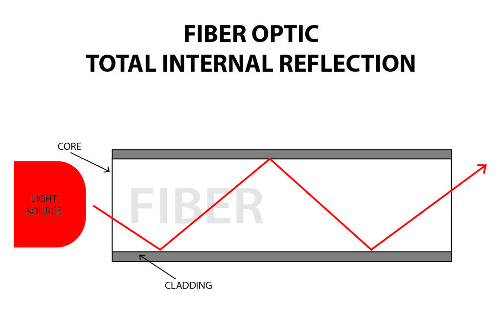
Fiber optic works because the light that moves along the fiber stays inside, is reflected in the brightness of the surface of the fiber. This is “total internal reflection”, or at least for the standard acrylic fiber, it is a high percentage of internal reflection and that is good enough. Therefore, to get light from the fiber at any point other than the end, you will have to disturb that internal reflection. A very easy way to do this is to simply curl the fiber beyond a certain angle.
How to Get More Light Out of a Single Strand of Optical Fiber Attached to an LED
- In my case, as my design for the optical fiber path was sinuous (not angular) use the edge of a scissors to wear the fiber and also sandpaper (fine). In the more worn sectors, greater reflectance of light can be observed
Useful liks and tutorials:
- Guide to Fiber Optics
- Kobakant Fiber Optics
- Fiber Optic Dress
- KOBA bolero
- Fast Fiber-Optic Light Pipe Hack With Sugru
- Fiber Optic LED Bling
Wearable optical fiber
FIber Optic Dress from Natalie Walsh on Vimeo.
Electronic System / Circuit and programming#
In the first place, it is necessary to make a schematic drawing of the circuit, calculate resistances taking into account the voltage (in this case 3V) to understand its operation. Then with the help of the Fritzing program, we introduce the same scheme that we physically tested on the bred board and it helps us to create the 2D drawing at scale, with standard parameters of the components, for its subsequent milling and optimal operation.
- Design of de PCB custom board by Ana Correa.
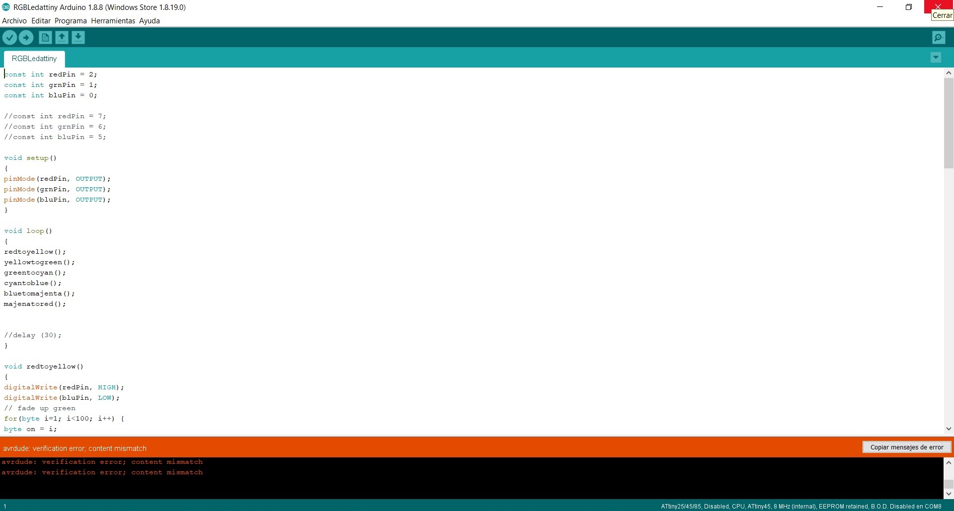
With Arduino, the code for the operation of the RGB LED is programmed, changing the colors in a loop.
const int redPin = 2;
const int grnPin = 1;
const int bluPin = 0;

//const int redPin = 7;
//const int grnPin = 6;
//const int bluPin = 5;

void setup()
{
pinMode(redPin, OUTPUT);
pinMode(grnPin, OUTPUT);
pinMode(bluPin, OUTPUT);
}
void loop()
{
redtoyellow();
yellowtogreen();
greentocyan();
cyantoblue();
bluetomajenta();
majenatored();

//delay (30);
}
void redtoyellow()
{
digitalWrite(redPin, HIGH);
digitalWrite(bluPin, LOW);
// fade up green
for(byte i=1; i<100; i++) {
byte on = i;
byte off = 100-on;
for( byte a=0; a<100; a++ ) {
digitalWrite(grnPin, HIGH);
delayMicroseconds(on);
digitalWrite(grnPin, LOW);
delayMicroseconds(off);
}
}
}
void yellowtogreen()
{
digitalWrite(grnPin, HIGH);
digitalWrite(bluPin, LOW);
// fade down red
for(byte i=1; i<100; i++) {
byte on = 100-i;
byte off = i;
for( byte a=0; a<100; a++ ) {
digitalWrite(redPin, HIGH);
delayMicroseconds(on);
digitalWrite(redPin, LOW);
delayMicroseconds(off);
}
}
}
void greentocyan()
{
digitalWrite(grnPin, HIGH);
digitalWrite(redPin, LOW);
// fade up blue
for(byte i=1; i<100; i++) {
byte on = i;
byte off = 100-on;
for( byte a=0; a<100; a++ ) {
digitalWrite(bluPin, HIGH);
delayMicroseconds(on);
digitalWrite(bluPin, LOW);
delayMicroseconds(off);
}
}
}
void cyantoblue()
{
digitalWrite(bluPin, HIGH);
digitalWrite(redPin, LOW);
// fade down green
for(byte i=1; i<100; i++) {
byte on = 100-i;
byte off = i;
for( byte a=0; a<100; a++ ) {
digitalWrite(grnPin, HIGH);
delayMicroseconds(on);
digitalWrite(grnPin, LOW);
delayMicroseconds(off);
}
}
}
void bluetomajenta()
{
digitalWrite(bluPin, HIGH);
digitalWrite(grnPin, LOW);
// fade up red
for(byte i=1; i<100; i++) {
byte on = i;
byte off = 100-on;
for( byte a=0; a<100; a++ ) {
digitalWrite(redPin, HIGH);
delayMicroseconds(on);
digitalWrite(redPin, LOW);
delayMicroseconds(off);
}
}
}
void majenatored()
{
digitalWrite(redPin, HIGH);
digitalWrite(grnPin, LOW);
// fade down blue
for(byte i=1; i<100; i++) {
byte on = 100-i;
byte off = i;
for( byte a=0; a<100; a++ ) {
digitalWrite(bluPin, HIGH);
delayMicroseconds(on);
digitalWrite(bluPin, LOW);
delayMicroseconds(off);
}
}
}
Assembly of the electronic system#
Step by Step:
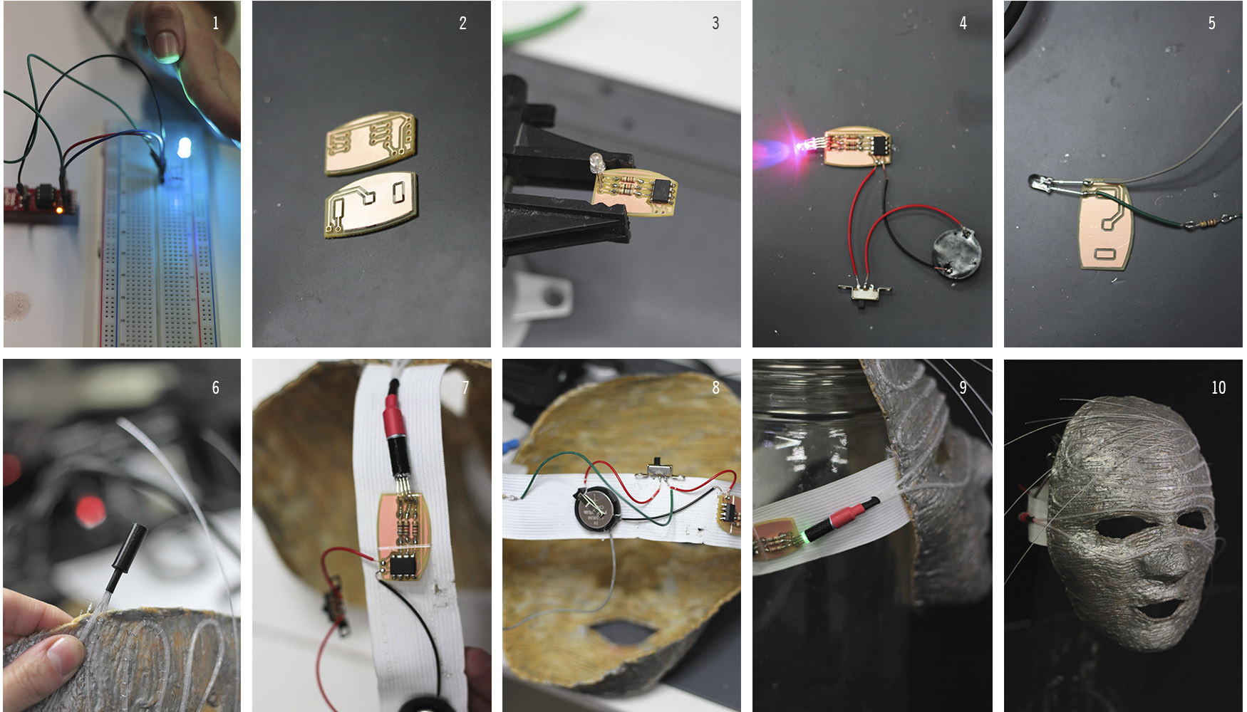
- 1 All the programming of the electronic system was carried out with the Arduino software and with the Arduino UNO board in its initial phase. First a test of the operation of the RGB led and the code was carried out. To adapt the system to the wearable, the ATtiny85 microcontroller programmed through the AVR board of Sparkfun was used.
- 2 For the circuits, a customized PCB board was designed using the Fritzing program. To print it, the CNC technology and the Rolland milling machine were used, so that the components of the circuit are mounted on its surface similar to the SMD style (surface mounting device).
- 3 Position the circuit elements: Led and their respective resistors (Red = R 68 Ω / Green and Blue = R 10 Ω) plus ATtiny85 programmed for its subsequent soldering.
- 4 To close the circuit, cables were used that connect the negative pole direct to the negative of the 3V battery and the positive pole to a switch (ON-OFF) and from there to the positive of the battery.
- 5 As I decided to add another light source to the other end of the optical fiber to give more luminance to the route, a simple power circuit for Led was mounted.
- 6 It is necessary to “encapsulate” the beam of light, for it was printed a piece to measure in 3D that at one end allows the entry of fiber optic filaments and on the other the right fit of the diameter and depth of the Led.
- 7 It is important to reinforce the connection and the possible escape of light between the LED and the fiber with a thermoformable tube. The elements of the electronic circuit were positioned and sewn to an elastic band sewn on both sides of the mask, which functions at the same time as an adjustable support.
- 8 Once the 2 Led light sources and their respective circuits have been placed and positioned, they are joined, sharing the same source (3V battery) and the switch that allows manual switching on and off.
- 9 It is necessary to leave the cables with excess margin and thus make it possible to stretch the elastic and reinforce its positioning with stitches by hand so that the circuit remains stable when putting on and taking off the mask.
- 10 Image of the finished mask, without lighting.
Week 12. SKIN ELECTRONICS / RGB Led / Check ATtiny85 microcontroller from Betiana Pavon on Vimeo.
Week 12. SKIN ELECTRONICS / customized PCB board / Rolland milling machine from Betiana Pavon on Vimeo.
Finished Mask#
Week 12. SKIN ELECTRONICS / Fiber Optic Mask from Betiana Pavon on Vimeo.