8. Wearables
Research and Ideation
I started this week with the idea of expanding my e-textiles library with more samples, this time including actuators as well.
References & Inspiration
Lisa Stark's mono amp adaptor was a source of inspiration for me to build a wearable speaker:
Pauline Van Dongen's Flip Dot Dress is an elegant way of embedding electronics into wearables pieces:
Tools
Textiles and other materials:
- Conductive thread
- Non-conductive thread
- Non-conductive yarn
- Embroidery fabric (cotton)
- Felt
- Coated copper thread
- Copper tape (sticky on one side)
- Fusing fabric
Tools:
- Needles of various sizes and tips (according to thread diameter and fabric that it goes through)
- Scissors (one for cutting conductive materials and one for cutting the rest)
- Utility knife
- Cutting mat
- Metal ruler
- Pen
- Lighter
Electronics:
- Arduino NANO
- Arduino IDE
- Breadboard
- Multimeter
- LED (various colors)
- Resistors
- Alligator clips
- Jumper wires
- RS PRO Jack Connector
- PAM8302 2.5W Mon Amp
- 3 AA Battery Pack
- 8 Ohm 0.25W speaker
- Attiny85
- Micro servo motor
- Heat shrink (different sizes)
Process and workflow
As a continuation from e-textiles week, this week we focused on microcontrollers and output devices. We followed a couple of tutorials together to get the hang of working with all the elements. Firstly, everyone in the lab made a Mono Amp Adaptor and a power circuit. We followed the same tutorials but made our separate examples with Michelle's guidance. Afterwards, we made a flipping wing with Emma using the power circuit. We also learned how to program an Attiny85 with Arduino Uno with Michelle.
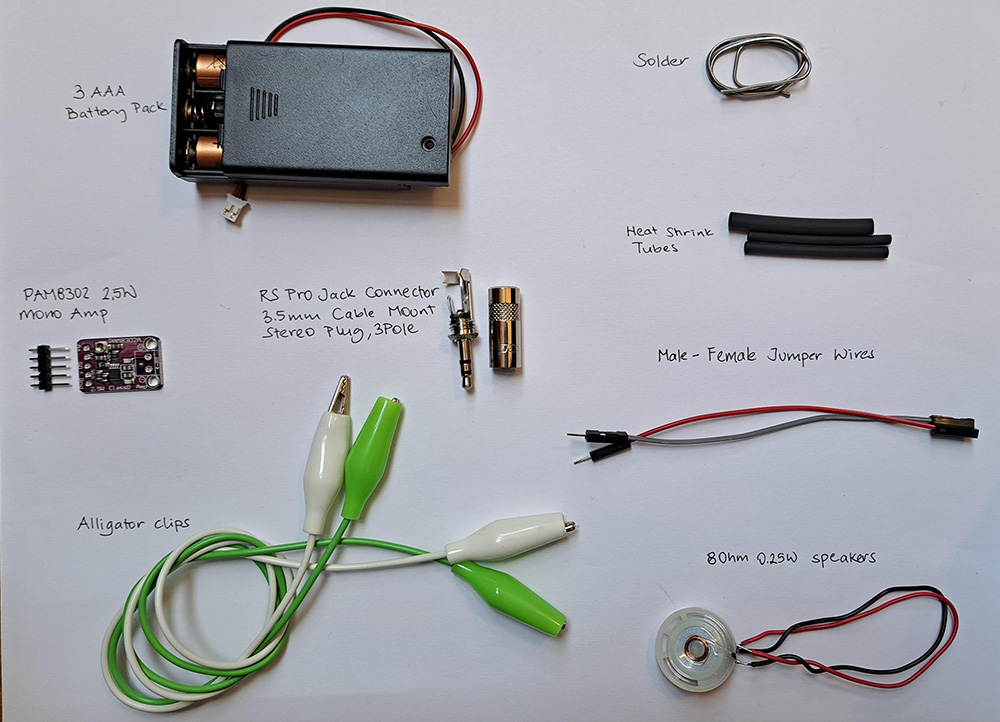
Mono Amp Adaptor
We made a Mono Amp Adaptor following Liza Stark's tutorial with a variation of the power source and jack connector.
We used the following components & parts:
- RS PRO Jack Connector 3.5 mm Cable Mount Stereo Plug
- PAM8302 2.5W Mon Amp
- 8 Ohm 0.25W speaker
- 3 AA Battery Pack
- Heat shrink (different sizes)
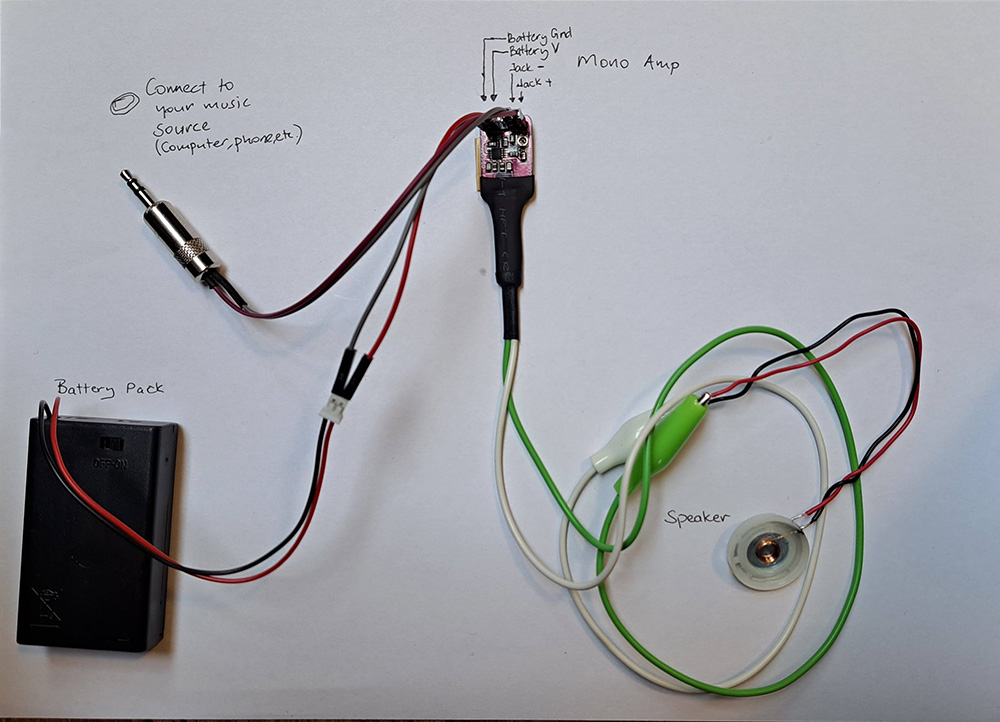
This mono amp speaker is used just like any other speaker with a jack, just plug it and listen to your music / sound. Since it is a mono amp, it does not create a stereo sound but a mono sound. Please ignore me singing in this video:
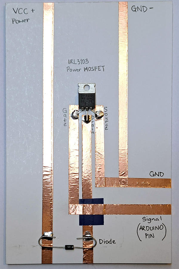
Power Circuit
We made a prototyping power circuit with IRL3103 HEXFET® Power MOSFET with diode using the previous years' samples as a guide. The datasheet of the MOSFET can be found here. We used a Diode 1N4001. MOSFET is a type of transistor. A transistor is an active component. Its behavior changes according to voltage applied to one pin (Gate). It behaves like a switch. It is especially important to use a transistor when dealing with higher voltages, transistors prevent frying the boards.
Flipping Wing
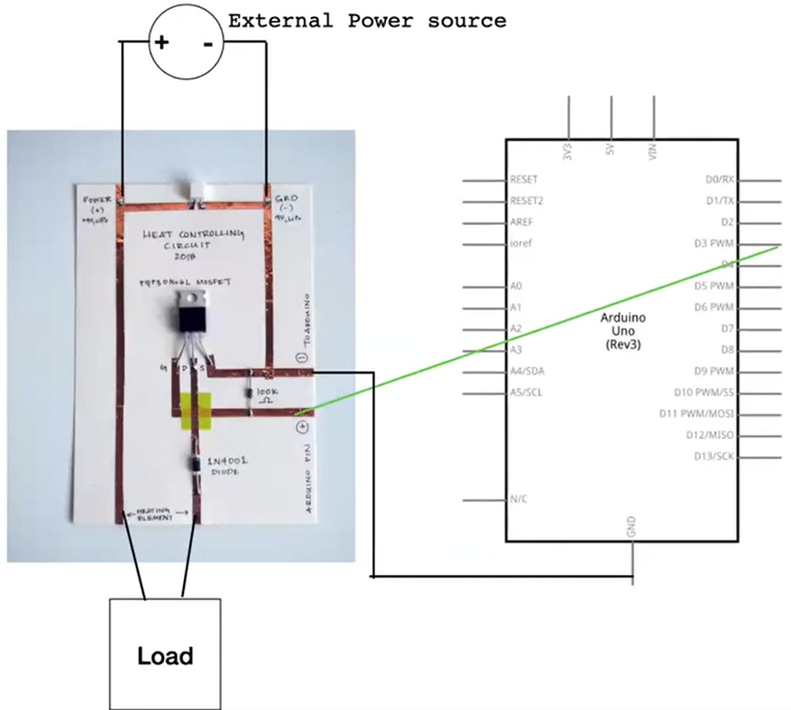
Flipping Wing combines a power circuit, an electromagnet and an Arduino Uno board.
You prepare an electromagnet by wrapping a coated coil around a pen by 50-100 times and placing a magnet underneath it. I wrapped it 75 times, middle has a charm. With the electricity current running or not running through your coil, the magnet repels or attracts the coil, causing it to move.
The circuit layout is as the following, you need to place your electromagnet where it says LOAD:
It uses the following code in Arduino IDE:
int load_pin = 3; //define the pin where the load (electromagnet) is connected

void setup() {
pinMode(load_pin, OUTPUT); //define pin of the load (electromagnet) as an output
}

void loop() {
digitalWrite(load_pin, HIGH); //turn the load on
delay(50);                 //wait 50millisecond
digitalWrite(load_pin, LOW);  //turn the load off
delay(50);                 //wait 50millisecond
}
Programming an Attiny85 from Arduino Uno
Michelle sent us the this Instructables link and walked us through the steps of how to program an Attiny85 from an Arduino Uno board. Learning how to program small microcontrollers is an important step towards creating embedded systems in textiles.
After programming the Attiny85, if you connect the V5 and GND pins of the Attiny to a battery, you can run your small circuit without the Arduino Uno board.
Note
If you have reverted your Arduino Uno to use as your Microcontroller and you want to use it again as a programmer for Attiny85, you need to program your Arduino Uno as a programmer but you can skip the Burn bootloader to Attiny step as it has been done already.
Individual Projects
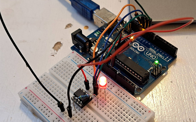
Adjusting LED brightness with force sensitive resistor
I had the Force Sensitive Resistor (FSR) from years ago that I never had used. So as a starting point into using my variable resistors (analog sensors from previous e-textiles week) I decided to use the FSR. I found this very helpful step-by-step guide on how to set up the FRS with and LED using Arduino.
It uses the following code on Arduino:
const int led = 5;     //sets the led pin @pin 5
const int FSRanalogpin = A0; //sets the FSR analogpin A0 to read analog input
int value; //saves the analog value
void setup(){
pinMode(led, OUTPUT);  //Sets led @pin 5 be the OUTPUT
}
void loop(){
value = analogRead(FSRanalogpin);       //This will read and save the analog value from FSR
value = map(value, 0, 1023, 0, 255); //This will map the value from 0-1023 to 0-255 (PWM)
analogWrite(led, value);          //Sends the PWM value to led
delay(100);                          //Delay of 100 milliseconds
}
The LED brightness adjusted according to the resistence read on the FSR:
I tested the same code with my conductive elastic crochet sample from e-textiles week. The result was very satisfactory.
Speaker coil
Note
You need to 4-8 ohm resistance in your coil to have a good functioning electromagnet.
Making the Mono Amp Speaker gave me the idea of testing out my test sample of a coil from previous e-textiles week. My coil worked really well as a speaker.
This test needed two improvements:
- The conductive thread of this sample is uncoated and I wanted to implement this etextiles inside my helmet from Open Source Circular Fashion week. The helmet was designed to be used while cycling and given the rainy days here in Amsterdam, I did not want rain to create shorts on my circuit.
- The speaker was not loud enough.
The idea of the coil being not visible as a spiral but as a field was what intrigued me, so I kept that design decision.
The new design of the textile swatch uses a coated copper thread. To make the speaker louder, I went over the embroidered parts twice to increase coil density and also placed two magnets instead of one. To make it a part of my swatch library, I glued the sample on my felt base.
Servo motor, moving garments
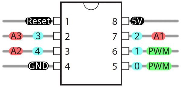
It is important to learn the pinout of the Attiny85 board. So, here is an image that explains the pinout for future reference:
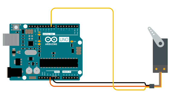
First, I started with understanding how to move a Servo motor through Arduino, the very basics. I used the this tutorial to have movement on my servo motor.
#include <Servo.h>

Servo myservo;  // create servo object to control a servo
// twelve servo objects can be created on most boards

int pos = 0;    // variable to store the servo position

void setup() {
myservo.attach(9);  // attaches the servo on pin 9 to the servo object
}

void loop() {
for (pos = 0; pos <= 180; pos += 1) { // goes from 0 degrees to 180 degrees
    // in steps of 1 degree
    myservo.write(pos);              // tell servo to go to position in variable 'pos'
    delay(15);                       // waits 15ms for the servo to reach the position
}
for (pos = 180; pos >= 0; pos -= 1) { // goes from 180 degrees to 0 degrees
    myservo.write(pos);              // tell servo to go to position in variable 'pos'
    delay(15);                       // waits 15ms for the servo to reach the position
}
}
Then, I moved on to moving the servo through Attiny85 board.
Note
Everytime you want to program an Attiny85 through Arduino Uno, you need to upload the ArduinoISP sketch from File>Examples>11.ArduinoISP to your Arduino Uno board first if you have used your Arduino for anything else. This sketch will turn your Arduino Uno board to a programmer.
Then you need to create the following circuit:
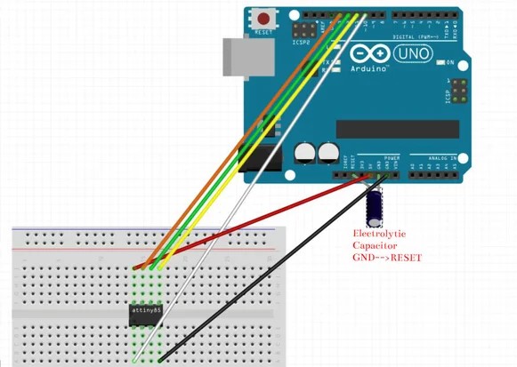
I used the information and the code from this thread as my starting point to move my servo motor. Because, I read that the servo library of Arduino is not supported by Attiny85. You need to connect the signal pin of your servo to Pin 4 on Attiny85.
void setup() {
pinMode(4, OUTPUT);
}

void loop() {
// keep sending 0 position for about 400ms
for(int i = 0; i<20; ++i) {
    digitalWrite(4, HIGH);
    delayMicroseconds(1000);
    digitalWrite(4, LOW);
    delay(19);
}

// keep sending second position for about 400ms
for(int i = 0; i<20; ++i) {
    digitalWrite(4, HIGH);
    delayMicroseconds(2000);
    digitalWrite(4, LOW);
    delay(18);
}
}
This servo motor was aimed to move the auxetic samples that I made in the Computational Couture week. However, I did not have the time to explore it further within this week.
Notes from the Classroom
notes from the classroom
WEARABLES lecture by LIZA STARK
Why we wear.. to convey a message to ourselves and to others, a second skin
Hardware of wearables -- small, flexible, wireless, what is the tradeoff?
HOW TO MAKE STH WEARABLE
- A design process -- A project is a system. Process -- ideate, research, prototype, test, refine, produce
- Functional considerations -- application, durability, wearability, washability, power, circuit layout
- Human considerations -- visibility, privacy, sustainability
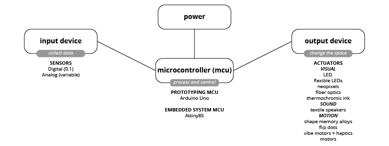
WHAT IS AN ACTUATOR? - an actuator is a component of a circuit that moves or controls another part based on input. It is an output.
- Visual
- LEDS - light emitting diode (elecricity moves in one way - direction) - smd (1206 is a good size), through hole (3mm, 5mm, 10mm, RGB leds), sewable LEDs (lillypad has them) - LEDs need 20mA to be at max brightness - in you are connecting LEDs to Arduino, you need a 220 Ohm resistor for each one.
- flexible LEDs
- neopixels
- fiber optics
- thermochromic ink
- Sound
- textile speakers
- Motion
- shape memory alloys
- flip dots
- vibe motors + haptics
TUTORIALS with MICHELLE
Always prototype with breadboard, with Arduino Uno, ATTiny or Adafruit Gemma
Not all libraries in Arduino IDE are compatible with all chips. Check them!
Audio: DF Player Mini (mp3)
MonoAmp
TUTORIAL by EMMA
Program:
- How to drive an output device with arduino
- Power loads: what they are
- Driver circuit: why you need it
- Build and control an electromagnet (flipping wing)
Microcontroller: Process and control
ARDUINO UNO
Power pins:
- All Ground Pins are connected to each other, so it does not matter which one you use.
- 5V / 3.3 V: Power pins (steady pins, they are always on when you plug the board)
IO pins (Input output pins): Read voltage (input devices), control voltage (output devices)
- A0, A1, A2, A3, A5: Analog sensors, digital sensors, Digital way output
- 0, 1, 2, 3, 4, 5, 6, 7, 8, 9, 10, 11, 12, 13: Digital sensors, Digital way output
- PWM pins (pins with tilde ~ sign): Analog way output
ARDUINO IDE
- setup (): code runs once, at the beginning when the arduino is powered on, define the pins.
- loop (): code runs repeatedly, line after line.
Always make pin connections when arduino board is unplugged!!!!
POWER LOAD
The max current that IO pin can source is 20mA
- Heating element: 500mA - 1A
- Memory Alloy: > 1A
- Flip-dot: >500mA (electromagnet)
- Vibrating motor: 65mA(3V), 92mA(4V)
Transistor is an active component. Its behaviour changes based on the voltage applied to one pin (Gate). There are different transistor types. Emma suggests to use MOSFET.
MOSFET has three pins: Gate, Drain, Source
Transistor behaves like a switch.