8. Open source hardware: from fibers to fabric#
This week we made a machine! At TextileLab Amsterdam we decided to make an incubating / material growing / drying machine with controllable temperature and humidity, that can be adjusted to grow or process a number of different materials. As this was a group project, we’ve worked together to document how to make the ‘Multi Process Machine here. My personal documentation is about the research and development of the electronics, which Wendy and I worked on.


Background#
During Fabricademy we’ve worked with a lot of different biomaterials, including bacteria and bioplastics. And within the Fabricademy community, others are growing things like kombucha and mycelium, drying materials like fruit leather, and making things like yoghurt, kimchi and tempeh. Some of these need specific temperatures to grow, or specifically humid / dry environments, and some of them just work better in the right conditions.

I’m also big into baking, and always find it frustrating when certain recipes are really dependent on the weather (e.g. macarons, which just won’t work )
For our Multi Process Machine we needed to be able to:
- Generate heat
- Measure temperature and humidity
- Display this information to the user
- Allow the user to set the desired temperature and humidity
We had a whole lot of ideas for other features, but as we only had a week for this project, we decided that these were the basic functions we needed to achieve. The six of us split into smaller groups to work on different parts of the machine, and Wendy and I teamed up to work on the electronics. She named us ‘Team Unicorn Rainbows’.
Choosing an electronic brain#
We used an Arduino as the brains our our machine: to read temperature and humidity data, control the heating element, and basically do everything. We started off using an Arduino Nano, which is smaller (but otherwise not a whole lot different from the Uno). We also considered using a Raspberry Pi Zero, but went with the Uno for the reasons below.

Left to right: Arduino Uno, Arduino Nano, and Raspberry Pi Zero
Arduino Uno -v- Nano#
- The power supplies we had in the lab had the right kind of jack for the Uno, but not the nano, and changing that or getting a new power supply wasn’t something we needed to add to our to do list :)
- The Uno, being a bit larger, is just that little bit easier to work with when you’re using a lot of different pins and have cables everywhere.
- We also thought that the 12V power supplies would be too high voltage for the Nano, whereas the Uno is able to take voltages of up to 20V and regulate them down to the 5V that it needs. However, I’ve since learned that the Nano can do this too ¯_(ツ)_/¯
Arduino -v- Raspberry Pi#
We also considered using a Raspberry Pi Zero to be the brains of our incubator. A Raspberry Pi is a small and cheap computer (made in the UK by a team of great people who do wonderful work in computing and technology education!), and the Pi Zero is the smallest and cheapest board they make. The pros and cons of Pi -v- Arduino are:
Points for Pi:#
- A Pi zero is cheaper than an Arduino, which makes the project accessible to a wider range of people
- Because the Pi is a proper computer, it would be relatively easy to have it record data on how the multi processing machine is behaving, and upload it to the internet
Points for Arduino:#
- Whatever program is uploaded on the Arduino starts running as soon as it’s switched on. It doesn’t need to boot up like the Raspberry Pi - being a proper computer - does.
- It’s comparatively simpler to write an Arduino sketch to do what we needed, and upload it to the Arduino, than to do the same thing on a Pi Zero. Not that it’s hard to do with a Pi Zero, but there are a few more steps involved.
- I have a lot more experience working with Arduino. I would have liked to use this project to brush up on my Raspberry Pi skills, but with only a week to build this machine, this wasn’t the time for that :)
Also, we had a couple of different kinds of Arduino in the lab. So this time, Arduino was the chosen electronics platform.
Research and Inspiration#
We decided that it would definitely make more sense to see what kind of similar machines other people had built, and modify an existing project (or at least take inspiration from others!). Some examples Wendy and I found particularly useful for the electronics included:
- Quantenschaum’s egg incubator
- Adafruit’s SousViduino project
- Digital Incubator by aliifrq on Instructables
Measuring temperature and humidity#
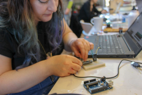
This project had a copule of different electronic components and techniques that were new to me. So instead of diving in and trying to build a complete circuit from scratch, a better plan was to build the circuit up gradually, adding each component, and understanding its behaviour, one by one (wherever possible!). The first thing to tackle was the temperature and humidity sensor.
DHT11 Sensor#
There are a number of different temperature and humdity sensors available that work with Arduino. We used a DHT11 sensor, which is accurate to within 1 degree, or 1% humidity. This is fine for our purposes, but for projects where a really accurate temperature, you might be better off trying the similar DHT22 sensor.


I downloaded an Arduino library (link at the end of this page) for the DHT11, and adapted a sketch from makerblog.at to create a test sketch to write the data being recorded by the sensor to the serial monitor.
//Simple sketch to read temperature and humidity data from a DHT11 sensor.
//Adapted from https://www.makerblog.at/2014/08/dht11-sensor-fuer-temperatur-und-luftfeuchtigkeit-am-arduino/

#include "dht.h"
#define dht_apin A0 // Analog Pin sensor is connected to

dht DHT;

void setup(){
  pinMode(dht_apin, INPUT_PULLUP);
  Serial.begin(9600);
  delay(500);//Delay to let system boot
  Serial.println("DHT11 Humidity & temperature Sensor\n\n");
  delay(1000);//Wait before accessing Sensor

}//end "setup()"

void loop(){
  //Start of Program

    DHT.read11(dht_apin);

    Serial.print("Current humidity = ");
    Serial.print(DHT.humidity);
    Serial.print("%  ");
    Serial.print("temperature = ");
    Serial.print(DHT.temperature);
    Serial.println("C  ");

    delay(5000);//Wait 5 seconds before accessing sensor again

}// end loop()
Sensor issues#
Wendy recommended that we buy two DHT11 sensors, to have one spare in case there were any issues, and this turned out to be a very good idea. One of the sensors worked fine, whereas another gave inconsistent readings, and generally didn’t seem to be working very well.
The moral of the story is: it never hurts to have spare components!
Setting target Temperature / Humidity and adding the LCD screen#
Setting up the LCD screen#
The next task was to wire up the lcd screen to the Arduino and display information on it. I followed this great tutorial by Adafruit, which walks you through the process step by step. Throughout the process of building hte project, I had to take apart and re-assemble the circuit a few times, and returned to this tutorial a number of times to figure out why the lcd had stopped working :)
In the lab we had an RGB lcd screen like this one from Adafruit. I wired up the screen according to this tutorial.
Using potentiometers to set target temperature and humidity#
Next I added two 10k potentiometers, connected to Arduino pins A5 and A6, to allow the user to set the target temperature and humidity


Using the code below, I now had a sketch that displayed the actual and target temperature / humidity to the lcd screen:
#include <dht11.h>
dht11 DHT11;
#define DHT11PIN 3

// include the library code:
#include <LiquidCrystal.h>

// initialize the library by associating any needed LCD interface pin
// with the arduino pin number it is connected to
LiquidCrystal lcd(7,8,9,10,11,12);

int target_temp_pot = A4; //this is the pin for the potentiometer that controls the target temperature
int target_temp = 0; //initialise the target temperature to 0
int target_humid_pot = A5; //pin for the potentiometer that controls the target humidity
int target_humid=80; //initialise target humidity to 0

// Update the serial display every 60 seconds.
const float UpdateSerialDisplay = 6000;

void setup(){
// set up the LCD's number of columns and rows:
  lcd.begin(16, 2);
  lcd.print("Initialising...");
  lcd.clear();
}

void loop(){
  int chk = DHT11.read(DHT11PIN); //read data from the DHT11
  target_temp=map(analogRead(target_temp_pot),0,1023,20,65); //Map that value from the range of the...
  target_humid=map(analogRead(target_humid_pot),0,1023,40,80); //...pot to the temp/humidity range

   //print the actual temperature to the lcd screen
  lcd.setCursor(0, 0);
  lcd.print("Temp:");
  lcd.print((float)DHT11.temperature, 0);
  lcd.print("C");
  lcd.print(" | ");
  //print the target temperature
  lcd.print(target_temp);
  lcd.print("C");

  //print the actual humidity to the lcd screen
  lcd.setCursor(0, 1);
  lcd.print("Humid:");
  lcd.print((float)DHT11.humidity, 0);
  lcd.print("%");
  //print the target humidity
  lcd.print(" | ");
  lcd.print(target_humid);
  lcd.print("%");

  delay(2000); //wait two seconds before taking a new reading
}
Heating element#
The part of the project that worried me the most was how we were going to heat the box, and control the heat. This was outside my electronics comfort zone! But Wendy and I did a lot of research into similar projects, and we also had a lot of help from Henk Buursen, the fablab manager at the Waag, and Emma Pareschi, who is the resident electronics queen.
Options, options, options#
Wendy and I were insistent that we didn’t want to use a heating element that needed a high voltage AC power supply, because a) we didn’t want to mess around with high voltages, and b) we felt the project would be more accessible if we stayed away from AC.
Chicken incubator heating elements#
Henk lent us a heating element from an incubator that he had taken apart, and we looked for a similar one online. We did find a place that supplied them, but it seemed like all of them needed 240V, so that ruled this option out
Light bulbs#
A number of DIY incubators use incandescent light bulbs as a heat soure, because these light bulbs work by heating a metal filament to the point where it’s so hot it starts to glow. This is a nice simple way to make use of waste heat from a bulb, but again requires high voltages, so we kept looking.
Kanthal Wire#
Kanthal wire is a type of wire that heats when electric current runs through it (aka it exhibits resistive heating). This is the kind of wire you find in hot wire styrofoam cutters, and one project we saw online used this as a heating element. We liked this because the wire isn’t expensive, and you can power it with a 12V power supply. BUT we couldn’t find anywhere in Amsterdam that could get it to us within 24 hours, unfortunately!
Printer bed heating element#
Wendy then had the bright idea to see if we could find a heating element that’s used to heat heated beds in 3D printers. and after researching this online for a while, we ended up being able to a couple of these from the wetlab in the Waag! Or rather, we now owe the wetlab a new heating element because the one we borrowed is soldered into our project :)

Powering the heating element#
Wendy did a lot of testing of the heating elements with an adjustable power supply, to see how hot we could get it, and what kind of power supply we would need to use with it. She has documented that in detail here. Emma helped us a lot with this part, and in the end we went with a 12V power supply that provides 1A of current. The heating element uses absolutely all of that 1A of current, so this meant we needed an additional power supply to run the Arduino.
Controlling the heating element with a relay#
Next we had to figure out how to control the heating element via the Arduino. As the heating element is being powered by a separate power supply, it’s not a simple matter of connecting it up to one of the pins. You can do this with a MOSFET, or a relay module - we used a relay! This is basically a kind of switch that interrupts one of the wires going to the heating element.
We tested the heating element on its own before integrating it into the rest of the circuit. To do this we hooked it up to an Arduino like the circuit diagram below, and just uploaded a simple sketch setting the voltage of the signal pin on the relay - Arduino pin A1 - to high. This closes the switch and allows current to flow - if everything is working, the heating element should heat up (and it did!).

Adding the fan and buzzer#
The last things to add were the fan (which distributes air around so that the temperature is consistent), and the buzzer (which alerts the user if the humidity is too high). The fan is connected directly to the +5V pin on the Arduino - this means it’s either on or off, and we can’t control its speed, but that was good enouch! The buzzer is connected to pin A0 on the Arduino. The final Arduino code is included at the end of this page. Here’s what our final circuit diagram looks like:

Soldering some of the components#
Wendy drilled holes in the box to allow us to put the components going inside the box - DHT11 sensor, heating element, fan - in place and run wires out to the Arduino.
Testing#
We just about had enough time to assemble everything and turn on the machine before it was time to present our project. After about an hour of heating we got the temperature up to 30 degrees, and it’s likely that with more time, and a bit more work on insulating the holes in the box (where the wires went it) this can increase. More work to be done!
Teamwork#
As this was a group project, it really put our teamwork and communication skills to the test. Whereas in previous weeks, we could all work at our own pace and set our own goals, this week we had to be in sync, and all had to make compromises so that we could work together to produce our machine. We chose a project that we felt would be functional and useful, rather than focusing on something that ensured an equal distribution of workload. I definitely think this was the right decision, but it meant that there was serious pressure on Team Unicorn Rainbows, aka me and Wendy, to get the electronics working, as this was a massive part of the project. But we got there! And within our mini team we worked really well together in getting all the different parts of the electronics figured out, tested and working (/◔ ◡ ◔)/
 These are two women who are glad this thing is finally almost finished
Appendix#
Extra troubleshooting tips#
Working with Arduino Clones#
For a lot of the prototyping stage of this project we were using an Arduino Nano, and when I started working with it, I had issues getting sketches to upload to it. I took a closer look at it and realised that there was no Arduino branding on it, which meant it was most likely an Arduino clone. And with clones, you often need to download additional drivers, or jump through a couple of extra hoops, to get them to work. What worked for me and the Nano clone was:
- Installing drivers, which you can find at this tutorial which explains why they are needed
- In Tools > Processor, choose “ATmega328P (Old Bootloader)”
After these two steps, it worked like a charm!
When good potentiometers go bad#
When we were finalising our circuit, we noticed that the readings from one of the potentiometers was fluctuating weirdly. When we turned the potentiometer to set a low target temperature, the values would jump around, seemingly at random. Emma figured out that at one end, the wiper of the potentiometer was no longer in contact with the material, so current wasn’t flowing through it, and the Arduino pin was just reading random values. Here’s an explanation of how potentiometers work if you’ve no idea what this means, but this is another good reason to always have a few spare parts around.
Possible future upgrades#
PID logic#
A number of the existing DIY incubator projects we looked at used something called ‘PID logic’ to control the temperature inside the incubator. This means using an algorithm that looks at the difference between the actual temperature and the desired temperature (and the same goes for humidity), and calculates what to do with the heating element (turn it on, or off, and for how long) based on an equation that has three parts:
- Proportion: how far off the desired temperature (or humidity) the system is
- Integration: Looking at the system’s past behaviour
- Derivative: How the system is changing, and what way the temperature is likely to change in the near future
I strongly recommend reading the PID section of the Adafruit SousViduino project for an in-depth explanation.
For our project we only had time to implement a simpler piece of code, which just says: - Is the temperature too high? Turn the heating element off - Is the temperature too low? Turn the heating pad on - Is the temperature about right? Turn the heating pad on and off at regular intervals.
For future iterations it would be great to implement PID logic, but that’s another day’s work!
Automating the opening of the vent#
While our final machine does include a vent at the top, which can be manually opened to let humid air out (or indeed, hot air), a nice upgrade would be to have a servo motor controlling the vent. We originally planned to do this, but dropped this from the plans because of time constraints. But this would be pretty easy and nice to add in future.
A Timer#
Another feature that would be super useful is an interface allowing the user to set a drying/growing/incubating time, and a buzzer to let them know when the time was up. Or even to add a bluetooth / wifi module that could send a message to their phone :)
Recording Data#
Adding an SD card module to the Arduino Uno would also be a nice addition, because that would allow the temperature / humidity data to be recorded, and this could be compared to the results of the growing/drying/incubating process. This could give new insight into why some bioplastic samples turn out better than others, and how fluctuations in temperature affect the growth of various different materials.
Accounting for a wider range of weather conditions#
At the moment, the Multi Processing Machine works well in relatively cold weather, where the materials you want to grow need a hotter environment than what you’ve got. It would be nice to work on the machine so that it could also create cooler, dryer temperatures, aka also be useful during hot summers!
Arduino Code#
//MPM1.1 - Multi-Processing Machine - 20/11/18
// Version 1.1:
//- Reads temperature from a DHT11 sensor
//- Controls a heating pad and fan using if/else logic
//- Controls the target temperature via a potentiometer
//- Displays the actual and target temperature on an lcd screen
//
//This is a Fabricademy project made at TextileLab Amsterdam. Arduino code by
//Jessica Stanley, with bits and pieces taken from the following sources:
//- Makerblog.at https://bit.ly/2QVaEY3
//- Adafruit's guide to setting up an lcd screen https://learn.adafruit.com/character-lcds/wiring-a-character-lcd
//- Quantenschaum's egg incubator project https://github.com/quantenschaum/egg-incubator

#include <dht11.h> //Library for the DHT11 temperature sensor
dht11 DHT11; //Set up an instance of the temperature sensor class
#define DHT11PIN 3 //Connect the data line of the temperature sensor to Arduino digital pin 3

#include <LiquidCrystal.h> //Library for the lcd screen
LiquidCrystal lcd(7,8,9,10,11,12); //Set up the lcd and tell the Arduino what pins to use

//Adjusting the target temperature and humidity
int target_temp_pot = A5; //pin for the potentiometer that controls the target temperature
float target_temp = 0; //initialise the target temperature to 0
int target_humid_pot = A4; //pin for the potentiometer that controls the target humidity
float target_humid=80; //initialise target humidity to 0

// Sensor calibration. Start with 0 for each.
const int HumidityCorrection = 0;          // -10 worked with my sensor. (original code)
const int CelsiusTemperatureCorrection = 0;  // 2 worked with my sensor.

// Update the serial display every 60 seconds.
const float UpdateSerialDisplay = 6000;

//other variables
int vent_open_time = 5000; //how long we want the vent to stay open, in ms
float T,H; //actual temp and humidity
int vent_state = 0; //is the vent open or closed? store here
int start_time,on_time; //keep track of how long the heating element has been on
int heater = A1 ; //heating element pin
int beeper = A0; //beeper

void setup(){
  Serial.begin(9600);
  lcd.begin(16, 2);   // set up the LCD's number of columns and rows:
  lcd.print("Initialising...");
  lcd.clear();

  start_time=millis(); //set the start time
  Serial.print("Start time is:");
  Serial.println(start_time);

  pinMode(beeper,OUTPUT);
  pinMode(target_temp_pot,INPUT);
}

void loop(){
  //Read the temp/humidity values from the sensor
  //add if statement to only do this every 2 seconds
  //if(millis()%start_time==2000)
  //{
  int chk = DHT11.read(DHT11PIN);
  T=(float)DHT11.temperature;
  H=(float)DHT11.humidity;
  on_time=millis()-start_time;
  //}

  target_temp=map(analogRead(target_temp_pot),0,1023,20,65);
  target_humid=map(analogRead(target_humid_pot),0,1023,10,90);

  if(T-target_temp>0.5){ // temperature too high
    digitalWrite(heater,LOW); // turn off the heater
    }
  else if (T-target_temp<-0.5){// temperature too low
    digitalWrite(heater, HIGH);// turn on hte heater
    }
  else {// temperature within acceptable range
    digitalWrite(heater,HIGH); //pulse the heater on and off so it doesn't continue heating
    delay(1000);
    digitalWrite(heater,LOW);
    delay(1000);
    }

    if(H>target_humid){
      digitalWrite(beeper,HIGH); //beep the buzzer! Let the user know that the vent needs to be opened
      delay(1000);
      digitalWrite(beeper,LOW);
      delay(100);
      }

// WRITING DATA TO THE LCD
 //print the actual temperature to the lcd
  lcd.setCursor(0, 0);
  lcd.print("Temp:");
  lcd.print(T, 0);
  lcd.print("C");
  lcd.print(" | ");
  //print the target temperature
  lcd.print(target_temp);
  lcd.print("C");

  //print the actual humidity to the lcd screen
  lcd.setCursor(0, 1);
  lcd.print("Humid:");
  lcd.print(H, 0);
  lcd.print("%");
  //print the target humidity
  lcd.print(" | ");
  lcd.print(target_humid);
  lcd.print("%");
}