8. Open Source hardware: from fibers to fabric
Result: the Squeegee2000*
Dutch: Trekker2000*
We built a prototype for a sheet casting tool to accommodate our needs and desires to produce large and evenly flat sheet materials made of bioplastics such as gelatine and agar-based ones, and the alginate plastics we made last week. We tested the machine by casting a sheet with alginate plastic. So far, the machine functions and we made a lovely 2mm sheet with it (which shrank a bit)l but could be improved by finding a better solution for keeping the walls together – the silicon glue didn’t hold. And also the wiper or squeegee could have a deeper wiping edge so the strips can act as walls. Excess liquid will creep up, and could be contained if the wiper sinks a little deeper by default. Anyway, details details. Here's our working prototype!
The machine might need some iterations but has potential to allow us to research shrinkage, cast the exact same kinds of sheets, comparing recipes etc etc. Even do small batches of production.
The process of creating the machine was challenging at first (see below), but as soon as we were on the same page and had a shared understanding of the goals, the technical nitty gritty, and names for things, we took off like a rocket and had a lot of fun even though loads of stuff of course went wrong (and got fixed) along the way.
Feedback
Mar: precision thickness was an issue for acrylic even just a few years ago, so nice idea to try this for bioplastics!
Mar: suggested to put a railing to keep the height precise. In the industry they control sheets by iterating and improving the methods for standardizing, so good start. And you're trying different things like textures and stamps so lots more to explore.
Anastasia: suggested to also include more technical drawings, maybe imagining how this machine might work in industry (more automated).
Response: Yes! We're working on an IKEA-style construction manual based on our Rhino files. It's taking a little longer though.
Question: How do you put calcium chloride below?
Answer: We don't, it dries very nicely with a beautiful gloss. It takes a little longer to cure because it only cures from the top, but the results are much nicer. It shrinks more than when you cast on top of a fabric though, this is true. But dat shine doe!
Brainstorm
After seeing the many interesting machines during the lecture, we were of course inspired and a little intimidated. We explored these questions: when is something a machine?, when is something a tool?, how important is it to us as a group to create a CNC tool this week?. In order to come to answers, we studied some machines in the lab and how they worked, how they were similar and how they were different. Which parts are interchangeable and which aren’t?
We discussed how some machines are easy to "hack" by changing the end actuator (replacing the knife of the vinyl cutter with a pen and similarly, inserting a paint brush into the big milling machine). And we got inspired by looking through the industrial processes listed in the book Materiology: The Creative Industry's Guide to Materials and Technologies by Daniel Kula and Élodie Ternaux that Cecilia suggested.
Research and inspiration
These are two machines I found that deal with flat materials, but not quite what we were looking for. But it's nice to see the feeding mechanisms I think. If you figure out the feeding, the moving of the material, you figure out half the machine.
 A few machines we studied from the Materiology book
We also looked up how for example acrylic sheets, but they are formed with heat, so that's quite a different process than the bioplastics we've been using because the set as they cool down or as a curing agent is applied. Still interesting though.
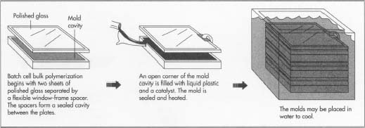 How acrylic sheets are produced, MadeHow article on Acrylic Plastic, 2006
I was also really into the machines by Shell Works! We watched their video during the lecture.
But our main source of inspiration was actually the week where we worked with bioplastics.
Desires and abstract ideas, and machine dreams
Consequently we did a solo brainstorm, writing down our ideas and desires on post-its, in whichever shaper or form they’d come. It was allowed to have more abstract or general desires/interests you wish to address with a machine, or they could already by concrete ideas for machines. We had a bit of everything, said them out loud, and stuck them on a big sheet.
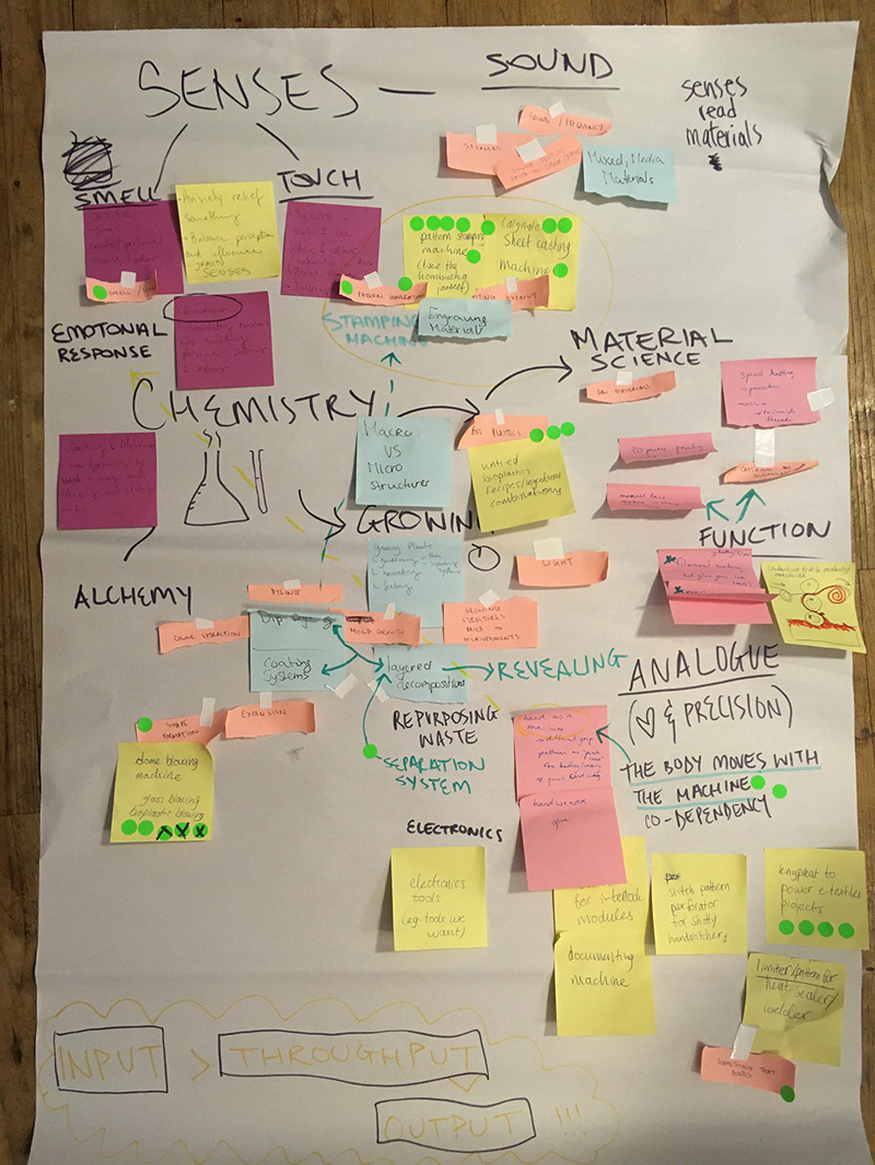 Impression of all the ideas we cooked up in our brainstorm, Loes Bogers, 2019
Then we did a dot vote: each person could give an idea one dot, one idea two dots, and one idea three dots. The ideas with a lot of votes were discussed more in detail, and we also assessed how realistic the idea was to do in a week, with the skills and knowledge we already have at the moment. Some ideas had been done before so they were also put aside for now.
More than making the majority vote count, we decided we wanted to end on an idea that everyone was passionate enough about. We would rather work on a machine that we were all at least excited enough about, than work on a machine that excites some a lot, but others very little. We confirmed that we were all pretty excited about the prospect of being able to cast thin sheet materials with a bit more precision, after our experiences during the bioplastics week. A sheetcasting tool it is! And not just a sheet casting tool, but one that potentially has a pattern stamping add-on module to also use our bio-based inks. This could be CNC one day, but for now, we’re all quite interested in making a manual mechanical machine. It’s an interesting challenge also, and analog is boss. If it’s not working you can use your hands, eyes and common sense to fix or adjust it, rather than having to dive into code and circuitry, which is not everyone’s forte.
Sketching through the machine
Finding the elements of the machine through sketching. We started at the bottom and started constructing the machine in our imagination and on paper, thinking through all the problems we could foresee, and trying to draw out conclusions for each.
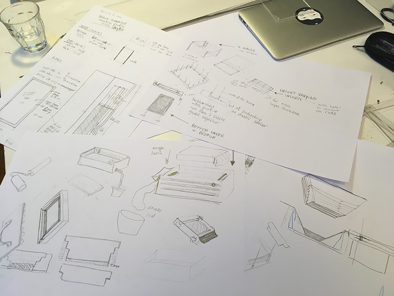 Impression of the amount of sketching we did, 2019
They helped us to literally get on the same page. Just not Bea's if you have heavy handwriting (;-) love you girl, amazing tech drawings you do). As we went through all the different parts that needed to be designed and made and assembled, something of a task division also emerged. We needed a watertight box with an acrylic bottom and walls. It needs an escape hatch to pour excess materials out of. We needed a squeegee or wiper to speed up the pouring process or for spreading thicker (slower) plastics such as the thick alginate recipes. But we also need a door to close the escape hatch in case we’re working with very liquid recipes. The walls need to be able to come out so you can fix a (textured) textile to the bottom and cast on top of that. We need 2D casting moulds to make nice textures, and maybe get some large pieces of textured fabrics that can cover the box. We asked Michelle to design something that allows us to also create rhythmic stamp patterns evenly.
Stamping module [INSERT NOTES MICHELLE]
We decided on a size of 500x1000mm casting area, and worked around that measure. We made a rough sketch to scale to see if we could cut all these parts out of the sheet materials we had available at the lab (acrylic sheets and triplex wood), this helped us make a shopping list, and off we went to the woodshop.
Shopping spree at Houthandel Schmidt
Our local woodshop Houthandel Schmidt is located in Amsterdam’s red light district, so it’s always a lively walk going there. It’s been in business for 150 years already and is located at a beautiful old squeeky narrow building. We feel like craft women already.
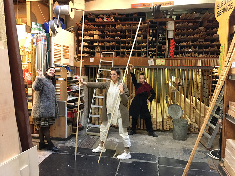 Us shopping at Houthandel Schmidt: Tens tens tens across the board!
The main thing we needed were metal rods to keep the wiper height strips stacked in place. We weren’t sure what to call them (in Dutch) though, and it continued to be a source of mixups and laughter. Luckily Cecilia already knew where to find these thingies in the shop so we could just point it out. But seriously though, is it a pipe, rod, a screw, a bolt or a metal stick? Maybe it doesn’t matter if you know where to get it. A conversation at the wood shop:
“What do you call those metal sticks?”
“A pipe”
“Yes but what if it isn’t hollow?”
“A solid pipe…A rod maybe”
“Ok, thanks. We already know where they are actually”
Measure everything
All your measurements are belong to us. The next day we measured literally everything:
- ~screws, I mean rods~, I mean bolts!
- sheet materials
- energy, fresh air and vibe in the room, brew coffee, take a walk or burn palo santo if necessary.
We found more problems and questions and figured out how we might solve them or which sizing we’d need to adapt. It was a combination of thinking through functions of the machine, sizes of surfaces needed, and techniques for constructing and keeping it all together.
Settling on shared terminology & toolology
Our names for stuff! Very important here. They might not be “correct”, they might not be “the technical terms”, but they work for us until they don't. What use are symbols and proper names if you don’t share them anyway? They are useless even if they’re not. And if you share them, why wouldn’t a different name work just as well?
- Absolute base layer: the bottom bottom layer, made of wood.
- Profiled base layer (inner and outer), the wood layer on top of the absolute base layer. Consisting of an inner rectangle, and an outer frame (made of wood strips)
- Rods, pipes, screws or bolts (may be used interchangeably in the context of our project)
- Length - Width - Height (OR thickness!): if you say thickness, we know it means height too.
- Walls: the acrylic sheets that stand upright
- Escape hatch: the front wall that has a wide rectangle cut out so you can push out excess liquid bioplastic
- Closing wall or door: the piece of acrylic that can be inserted to close the escape hatch, in case you are using very liquid recipes that spread easily by themselves.
- Wiper thingy or squeegee: a wide strip of acrylic that rest on the acrylic wiper-height-adjustment-strips mounted inside the walls of the box. By moving it along the strips you can spread the mixture towards the escape hatch evenly. It has the depth marked on it.
- Acrylic wiper-height-adjustment-strips: acrylic strips with holes in them that you can stack up to create the desired height/thickness of your material. Each strip adds 4mm height that you can tweak by using a wider or narrower squeegee.
- Rubber ducking: helping somebody by letting them talk through their problem without actually responding to anything they say. Talking at you is usually enough (and can therefore be done just as well by a rubber duckie). If you do respond you are a rubber duck with a big mouth (like Loes hahahaha).
- Caliper: the useful tool to make very precise measurements by clamping it from the outside, or pushing against inside walls. Schuifmaat in Dutch. The digital is easy to read (zero it first!), with the analog: the 0 marked on the bottom ruler is the pointer that points to the position to read on the top ruler.
- Decoupeerzaag (EN: handheld electrical jigsaw), the electric saw to cut through sheet material relatively easily. Different saws required to cut wood vs. acrylic vs. metal/PVC/etc.
- Straight angle = steel square = carpenter’s square = Dutch: winkelhaak or rechte hoek
- Penetrator - drilling bit to make wider holes to make screws disappear. The technical term is – boooooring – countersink or counterbore milling bit, Dutch: verzinkboor.
- Flowering effect (of badly used penetrator) - when a countersink milling bit makes flower shapes instead of circles.
- Diameter symbol: ⌀
- Industrial nailpolish a.k.a. Fast drying acrylic glue that comes in a bottle with a brush.
[INSERT] An overview of our tools and our lovely naming scheme, Paulina Martina, 2019
Inching in on sizes and settings
After all the rough sketching and measuring, Bea made beautiful softly drawn technical drawings of all our 2D parts. Loes unintentionally botched them up a few times with her heavy hand but Bea was forgiving and has an eraser, thankfully. In this part of the process we nailed down the final exact sizes by thinking desired workspace and construction needs in tandem. We want 50x100cm workspace to cast a sheet so it’s easy to measure how much it shrank and you can make nice stamping templates for it that have a round number for measurements (e.g. 25x25 mm). We also thought about ways of assembling and reverse engineered the design from that:
- Paulina did some tests to find the perfect width of the profile in the bottom layer to support acrylic walls. We thought we’d need to spread acrylic across the sides of the profile, but it wasn’t necessary. With Loes they found a manual way to make a snug fit to keep the walls standing upright.
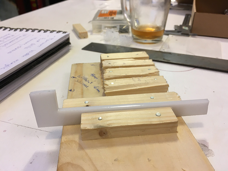 Manual precision technique to create a snug 4 mm profile to sink the walls into, by Paulina and Loes, 2019
- Testing screw, I mean rod, I mean bolt holes (shaft diameter vs. screw wire diameter!) > 5.65 mm for 5.7 mm bolt diameter.
- Finding settings to laser cut 4 mm acrylic. Finding the safe zone that works across the bed, testing with pieces big enough to let the laser catch up to the set speed (min 10 cm test pieces). Speed 18 power 100.
- Tips for resizing array of 7 holes in Rhino file: delete, make new array, center array in the middle.
- Tools have sizes and limits too: successful and unsuccessful tools to saw a 200cm acrylic sheet in two to fit it into the laser cutter (which also has dimensions).
Analog is boss: improvised and accidental precision is still precision
For this prototype we are proud and digging the improvised and accidental precision that was possible without getting very technical about the engineering and design. Sometimes common sense and a trustworthy reference material is all you need. We realize that actually we take for granted how many things are standardized nowadays. We can just count on the fact that 6mm screws are available, that an acrylic sheet that is advertised as 4mm is actually that thickness all the way across. How did people make stuff before standardization of screws etcetera? Infinitely harder, we imagine, and relying on different measuring materials that are actually very interesting. You can also see the locality (vs. universality) of such a reference material used for measuring and comparing. The standard meter (as a size) for example originated in France, and is defined as a measurement relative to Paris, no surprise:
”The French originated the meter in the 1790s as one/ten-millionth of the distance from the equator to the north pole along a meridian through Paris. It is realistically represented by the distance between two marks on an iron bar kept in Paris. The International Bureau of Weights and Measures, created in 1875, upgraded the bar to one made of 90 percent platinum/10 percent iridium alloy.” – The Standard Meter
Two wonderful accidental and manually achieve precision in our process: * Finding out that the wooden bottom (10mm) + acrylic bottom (2mm) equal the height of your outside frame (12 mm) by accident = precision <3 * Pressing two wooden sticks together with a 4mm thick piece of acrylic in between and then nailing them to a substrate (while pressing them together) is a perfectly fine improvised way of achieving a nice and tight 4mm profile. It's snug alright. Boom.
The main work: communication and patience
Expressing what you mean and making sure the other person understands it the same way and can respond is incredibly complex and time consuming. Considering that we are building a machine and with all talented and capable improvisers but we don't have an engineering background or shared lingo to fall back on! We took up sketching, drawing, note taking, doing build tests and demonstrating with stand-in materials as tactics to turn to when talking and listening were insufficient or too energy consuming for the amount of brainpower we had left. But we also talked a lot of course, about what the words we agree to use, division of tasks, checking in on each other, asking for help, giving compliments and cheering along. We also shut each other up quite a few times, hahahahaha.
We brushed upon each others limits here and there. Emotions might have been expressed too. But nothing crazy and lots of cookies. And coaching by Bela :)
Cutting
Bea did a super job designing the cut sheets for our machine!
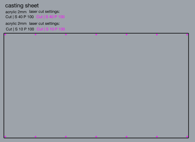
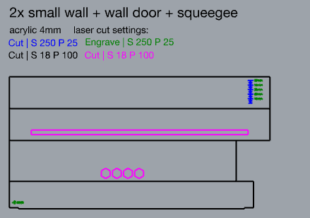
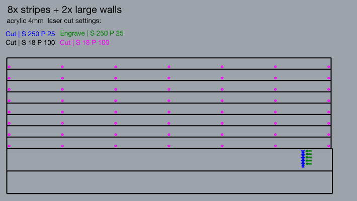 Cut files for the Squeegee2000, Beatriz Sandini, 2019.
During the cutting process we ran into quite a few hurdles, that we overcame, of course. But it was annoying too. Our design file was made in Rhino, exported as. dxf (trying all possible export settings), and using LaserWorks software to send files to the machine. Some issues and their solutions:
- Error message when trying to send job to engrave TEXT to the machine: “polylines not closed”. Solution: > Tools > Unite Lines
- Error message when trying to send job to engrave LINES to the machine: “polylines not closed.” This makes sense because they’re lines. Instead: we sent a cut job with engrave settings
- Error message: “soft dog error”. We hate soft dogs! This error appears and nobody’s sure why. The machine just can’t compute some of the lines. Close and open the program? Nope. Re-export dxf file using different settings? Sometimes. Can you verify that the machine can calculate a cut path that makes sense? No? Probably there are overlapping lines in your drawing that can be simplified. E.g. two rectangles perfectly aligned need only one cut where they intersect, but when you draw two rectangles there will be on top of each other. Go back to design.
- random diagonal line: we got a random diagonal line cut onto our material (with engrave settings thankfully, so not all the way through). This was NOT in the design! This laser path should send the laser to its starting point from where it starts cutting, but for some reason it generated G Code that turns on the laser too early. We’re not sure why.
- Cutlines are not all the way through: we mixing up the speed and power values (a classic!), we set the power value (100) for speed and the speed value (18) for power. Power 18 at Speed 100 only makes a dent in 4 mm acrylic. Don’t move the material! Don’t change the anchor point! Adjust settings and run the job from the same anchor point.
- We tried to cut 10mm thick wood sheets but could not get through well even at power 100, speed 10. So Henk cleaned the lens of the laser for us. This helped and we could cut it well at Speed 12, Power 100.
- We did a cuttest to allow the bolts to fit well, but found out that we measured the smooth shaft, but not the screw wire (which is wider). As a result, the bolts are quite hard to go through at first and then – when they reach the smooth shaft part – are a bit loose. Which is fine when they are in the box, but it makes it very hard to add and remove the height strips if you want to alternate between casting thicker and thinner materials. Bela went to get smaller bolts.
Rhino design tips (now we’ve found all cutting hurdles)
[INSERT] Bea's notes here on exploding and exporting!
Assembling
Time to assemble! We will list this order on hindsight, because we had to figure out what was a clever way to do it, and had to go back and redo many things that weren’t such a good idea.
- Manually drill caves for the bolt caps to sink in (bottom of profiled base layer)
- Insert bolts into profiled base layer from below Place profiled base layer onto absolute layer and center
- Hold acrylic walls in place, put wooden sticks for profiled base layer outside them and mark with a pencil to cut to size. Cut to size and file off.
- Push wooden sticks firmly against profiled base layer with acrylic wall and nail into absolute layer with a hammer. Add screws if width of sticks allows and they don’t splinter. Check that nails and screws are not too long…
- Glue the corners of the walls together with acrylic glue – the one that dries in seconds - hold until firmly attached. Don’t wiggle or move it though. This isn’t a strong connection (yet). THIS STEP NEEDS IMPROVEMENT/ALTERNATIVE SOLUTION
- Spread thin layer of transparent silicon (the one used for bathrooms) across the outside seams of the walls while they are sitting inside the profile. Put a plastic spacer on the wood so you don’t accidentally glue the acrylic to the wooden profile (needs to remain detachable for insertion of textiles). THIS STEP NEEDS IMPROVEMENT/ALTERNATIVE SOLUTION
- Let the silicon dry. Then take frame out, spread silicon layer alongside the inside seams. Finish the outside seams that were inside the profile before. Let it dry. THIS STEP NEEDS IMPROVEMENT/ALTERNATIVE SOLUTION
- If necessary: file off the corners of the acrylic wiper height strips and change in design ;) When dry, place the walls back into the profile. Add desired amount of acrylic wiper height strips. Cook up a batch of bioplastic and test it!
Tools used:
- Hammer and nails
- Screws
- Handsaw
- Ruler and iron hook
- Electric hand drill
- Counterbore milling bit
- Acrylic glue (fast-drying) > FIND ALTERNATIVE SOLUTION
- Silicon for bathrooms > FIND ALTERNATIVE SOLUTION
Notes on assembling:
- Measure how deep your nails and screw sizes can go before nailing or screwing the boards to the floor. Check that you have nails and screws of that size before you start to assemble ;)
- We cut the wood strips the wrong size because we forgot to place the acrylic sheets in between first. So they were shorter than intended and didn’t align neatly. They could still do the job but it doesn’t look as nice.
- Nails don’t hold as well as screws. You can position with a nail but it’s more secure if you do it with screws instead. If you are doing it proper, maybe design in some screw holes before, rather than improvise after.
- Stop working when you’re tired or you will put rulers upside down and silly things like that.
Manual drilling and other improvisations
- We rotated two of the wooden strips for additional height on the sides of the box
- We opened holes that turned out a little too small using a rats tail (it’s cheating, we know)
- You can do a lot of the manual labour by making a design and cutting the sheet on the shopbot, including making a profile, adding screw holes, and making the counter bores for the screws to sink in. Can all be done neatly with the shopbot, but we didn’t learn how to use that yet.
- We made a mistake in the escape hatch (it was wider than the closing door could cover). We re-used that part to cover the wood surface outside the escape hatch, for easier cleaning.
- The acrylic glue and silicon didn’t hold sadly. But even without it we managed to cast a sheet quite well. We need to find a solution for it but we have something of a working prototype. Maybe designing snapfit connections for the corners of the wall would work?
- Wood might not be the best pick for material because it absorbs liquid, like the calcium chloride you spray onto alginate. We coat treat the wood with a coating to protect it, or make this from a different material.
We are also creating an IKEA style instruction manual to go with the designs for anyone who would like to recreate it.
 Fragment of the instruction manual being designed by Paulina Martina, 2019
Mould and template design process
Software: Adobe Illustrator *Process: *
- Set-up an Artboard to the dimensions of the machine bed; In this case we removed 2mm from L and W to allow comfort fit L: 99.8 cm x W: 49.8 cm
- Start with drawing a symmetrical shape (triangle, square, hexagon)
- Duplicate the shape by holding Shift+Opt and dragging to the right.
- Create an even row of shapes (depending on the size of shape amount per row will differ per stencil)
- Duplicate down the page using Command+D.
- Play with Effects
- Effect > Distort & Transform > Twirl
- Effect > Distort & Transform > Twist
- Effect > Distort & Transform > Bloat
- Save file out as AI or DXF.
- Open DXF File in LaserCut 5.3 Software.
- Adjust scale of file in LaserCut 5.3 to match file dimensions in Adobe Illustrator.
- Adjust settings for cutting 2 mm ACRYLIC: SPEED: 40, POWER: 40, CORNER POWER: 20
 Bela's casting stencil designs, Bela Rofe, 2019
Texture buying trip
We took a trip down the lane, in the rain, to our local fabric merchant; A. Boeken Stoffen & Fournituren Winkel. We showered ourselves in different textured fabrics- imagining how we could use them as texture moulds for our plastic casting. We decided to go with options that were water resistant and strength in texture. Pattern Plastic.
 Selection of Textures Chosen for Casting, Bela Rofe, 2019
Testing
- MACHINE: Squeegee2000
- DATE: 11 . 11 . 2019
- TIME: 16:30 PM
- PLACE: Textile Lab Amsterdam
- CASTING: Bio Foil (Alginate based)
- CURING: Calcium Chloride solution 10%
Recipe for 2mm alginate:
- Water - 1000 mL
- Glycerine - 175 gr
- Alginate - 40 gr
- Dyes - Turmeric | Ethanol , Beetroot | Water
On Monday evening Bela and Bea dived into the first test cast on the Squeegee2000. They cast a beautiful 2mm thick sheet (before shrinking). The notes and conclusions from the test are already written into the process and conclusions above.
Shrinkage after 1 day:
- 1000 to 790 mm = 21% on the long edge
- 500 to 365 mm = 27% on the short edge
We imagine the difference in shrinkage across the length vs. width has to do with maybe the longer distance giving more surface friction between the alginate and the acrylic substrate so it moves less?
Celebrating

Credits
Concept: everyone! Machine design: everyone! *Snack supplies: everyone!
And then we took a lead on different things each, while still assisting each other where needed:
- Technical design plan: Loes & Bea
- Technical troubleshooting and improv due to oversights in technical design plan: everyone!
- Digital design in Rhino: Bea
- Rubber duck (with opinions): Loes
- Construction testing: Paulina
- 2D mold designer: Bela
- Toolguide: Loes
- Pattern stamping module: Michelle (WIP)
- Texture buyer: Bela
- Sustainability consultants: Bea & Bela
- Coach: Bela
- Assembly: Bea, Bela, Loes
- Testing: Bea & Bela
- Chef cook (of big bioplastic batches): Cecilia
- Instruction manual designer: Paulina
- Documentation: Loes
- Lead photographer: Bela
- Disaster and financial support: Cecilia ;-)
- Laser support: Henk!
Lecture notes
Notes from the lecture by Varvara Guljajeva
The origins of knitting; it's a very old craft. Dates back to 400-500 BV.
Hand-cranked circular knitting machines for socks!
The knitting machine was the first personal manufacturing tool at home. Brother used to produce a lot of machines but discontinued at a certain point.
Inspiration
Knitic
Post-functional wearables
Neuroknitting - Varvarag
Glitchknit.jp
Oiko-nomic threads
ayab-knitting : alternative way to control the Brother KH-9xx range of knitting machines using a computer.
Openknit and Kniterate
Idda knitting machine
Kniterate.com
Ecal - Rocking Knit
Wind knitting factory
>> A lot of the examples are exploring new or open source ways of making textile patterns.