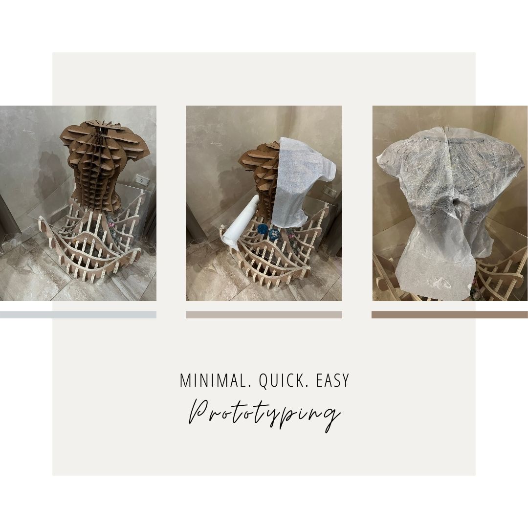
Initial Prototyping
Some of the Useful mentoring sessions comments I got: Were to prioritize the biomimicry effect I wanted to create exactly with that one specific location based on the timeline there as I can't do it all if it's too much
- After choosing one spot only for the biomimicry the mentors helped to focus on the part created inspired from there as they liked the story telling of this creature coming out of a dead sea inspired from this Deadsea As there as this main front piece would it be 3D printed flexible, printed 2D transformed 3D by heat? you have to specify
- One of the most important was if I wanted to include electronics to make sure to water proof them and maybe limit them in the dress ( and that actually made me put the electronics in the final outcome as in head piece and so to avoid being in the water …)
- to start with 3d printing then level it up from there if I had time I continue with the electronics (and that's what I did)
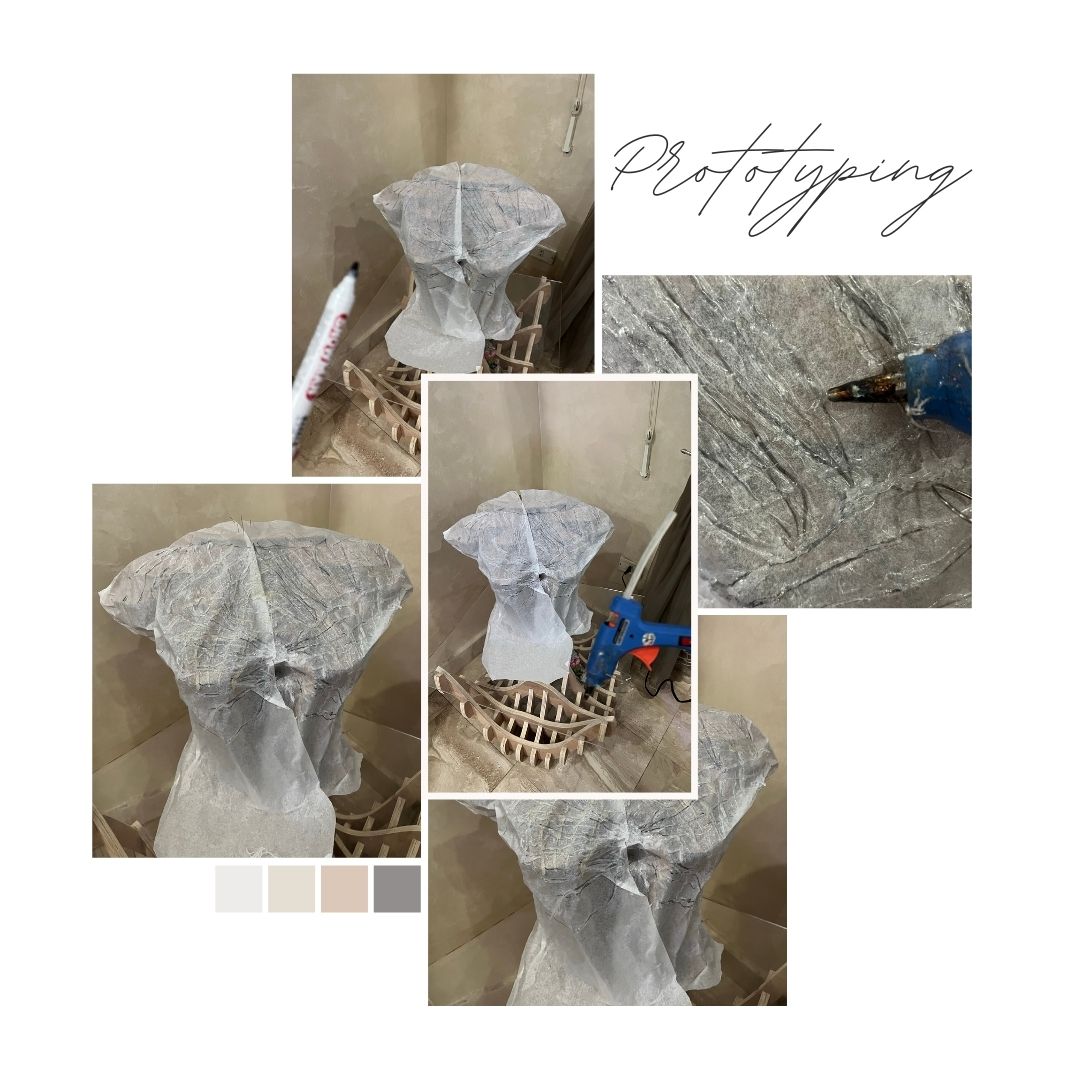
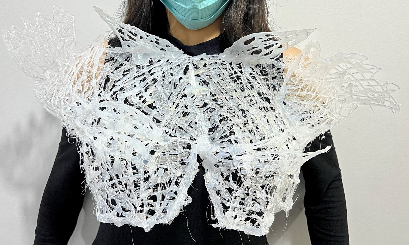
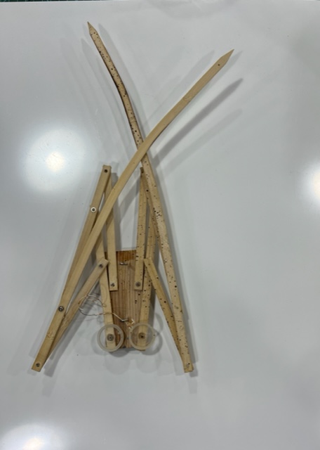
Prototyping
Quick and dirty prototyping of the creature wearable (I wanted some transparency in color) I was as well checking how and where would it be on the body.

Thermochromic
more details in the wearables week10
Research
she used Heating Circuits for Thermochromic Inks
Prototyping
Thermochromics
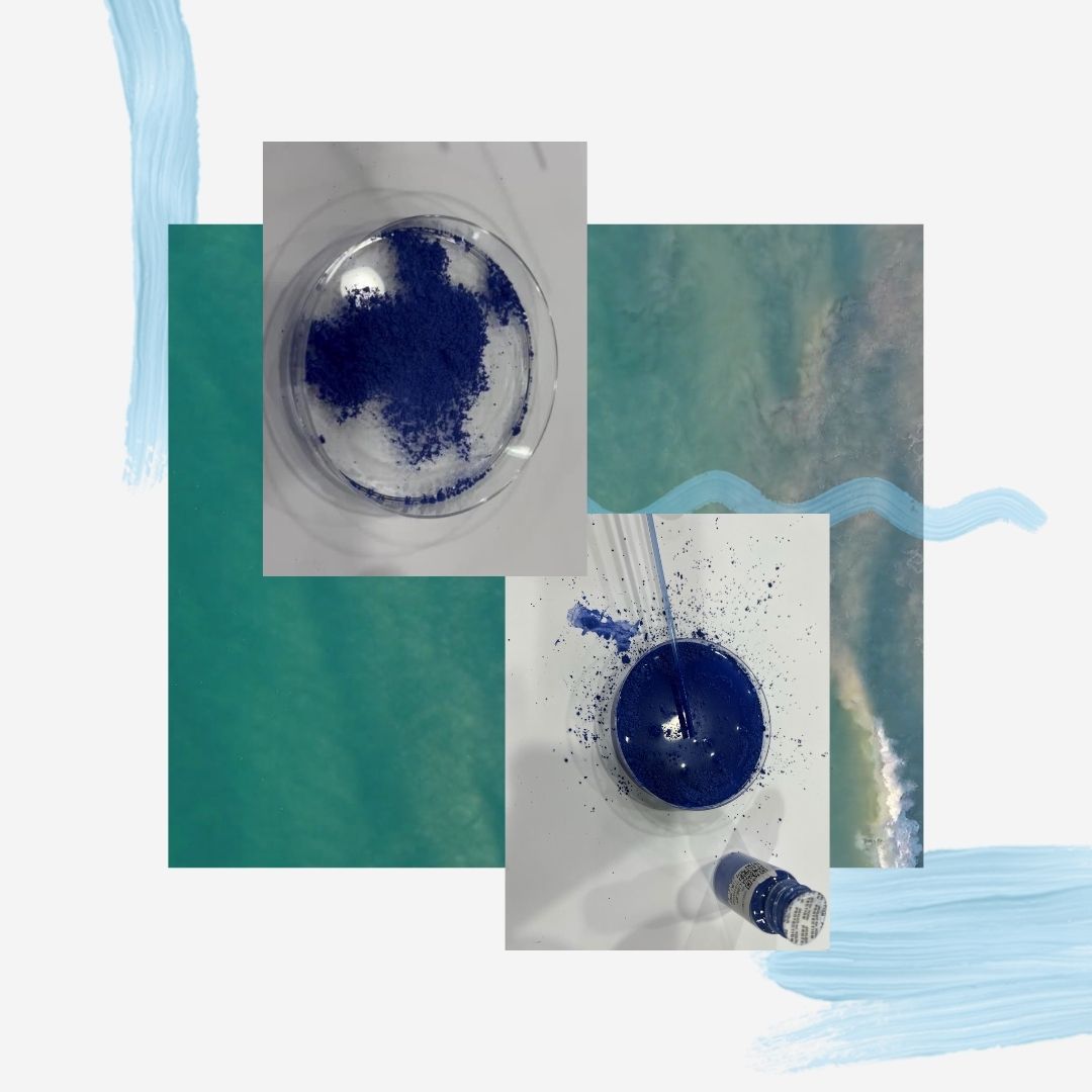 so I started by taking some thermochromic pigment … mixing it with water in a Petri dish... mix mix mix
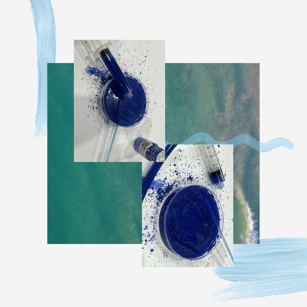
I tried my best to add more and more pigment until the solution is very well saturated as you can see in the picture so I have excess pigments can't be dissolved (cuz I wanted the most dense color I can possibly get)
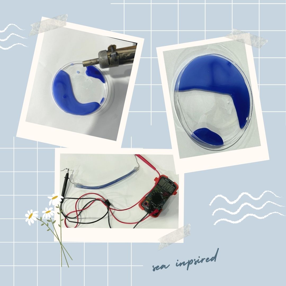
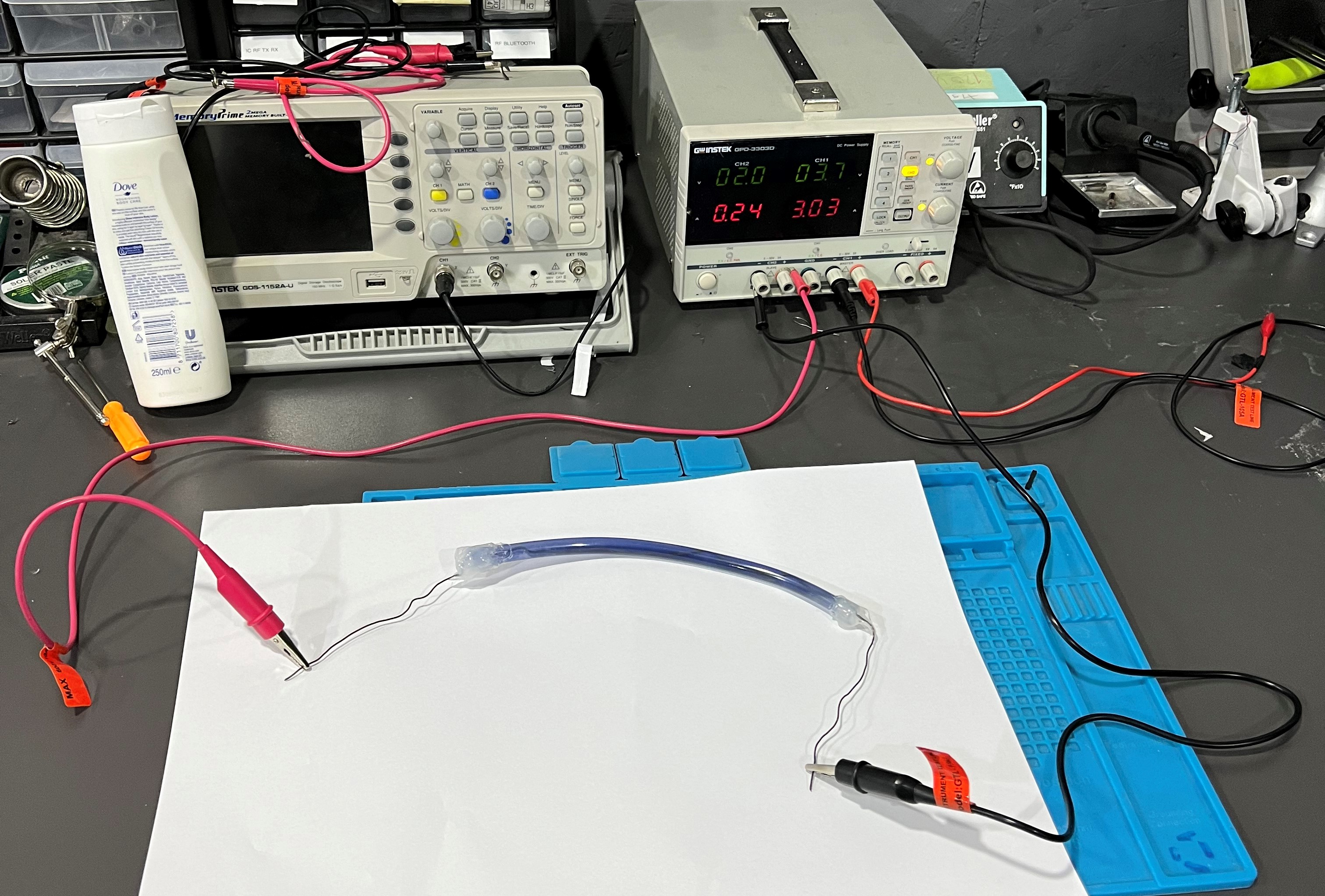
I prepared the tube by inserting the conductive metallic (iron) through the tube and locked on side via silicone gun so I have one end open then I took some of the thermochromic mixture using syringe to insert it inside a tube
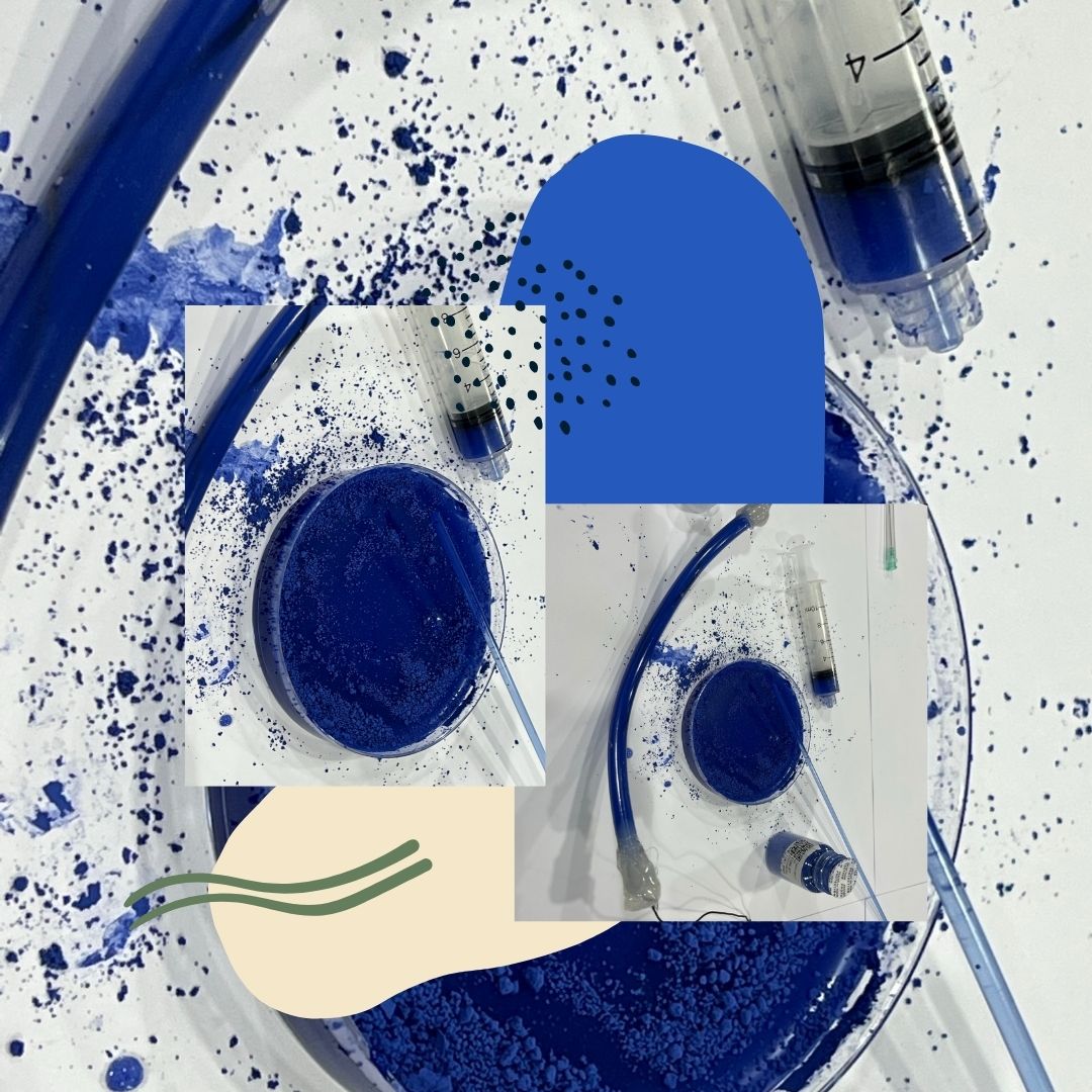
then after I filled the tube with the mixture I closed again with silicone gun
I tried to connect it to very low voltage as when I measure the resistance of the conductive iron was very low like 0.8 !!! so a short circuit would happen ...
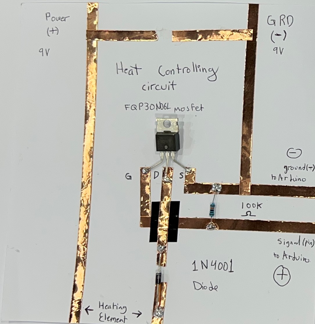
Heating Circuits for Thermochromic Inks
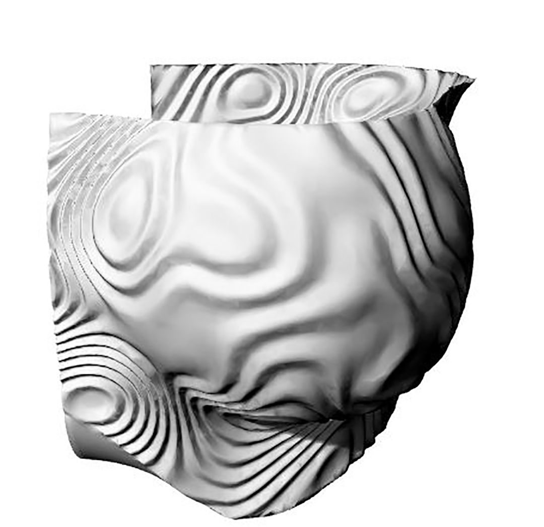
Crystals
Computational Design & 3D Printing
Electronics
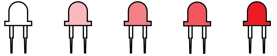
to achieve more color changing for some interesting drama for the project and to get cooler result I had to dig deeper in LED color changing
ESP8266 NodeMCU PWM with Arduino IDE – Dim LED (Analog Output)
starting by knowing how to generate PWM signals with ESP8266 NodeMCU using Arduino IDE. As an example, I’ll dim the LED brightness by changing the duty cycle over time.
ESP8266 NodeMCU Web Server with Slider: Control LED Brightness (PWM)
I was following a tutorial that shows how to build an ESP8266 NodeMCU web server with a slider to control the LED brightness. I'll Take you with me through the learning process of how to add a slider to the web server projects, by getting its value and save it in a variable that the ESP8266 can use. Using that value to control the duty cycle of a PWM (Pulse-Width Modulation) signal and change the brightness of an LED. Instead of an LED you can control a servo motor, for example(but I had previously controlled servo motor with my fav academy project so let's dig in an LED this time)
To generate a PWM signal on the ESP8266 pins with Arduino IDE, use analogWrite(pin, value). The value is an integer between 0 and 255.
ESP8266 NodeMCU PWM (Pulse-Width Modulation)
The ESP8266 GPIOs can be set either to output 0V or 3.3V, but they can’t output any voltages in between. However, you can output “fake” mid-level voltages using pulse‑width modulation (PWM), which is how you’ll produce varying levels of LED brightness for this project.
If you alternate an LED’s voltage between HIGH and LOW very fast, your eyes can’t keep up with the speed at which the LED switches on and off; you’ll simply see some gradations in brightness.
That’s basically how PWM works — by producing an output that changes between HIGH and LOW at a very high frequency.
The duty cycle is the fraction of the time period at which LED is set to HIGH. The following figure illustrates how PWM works.
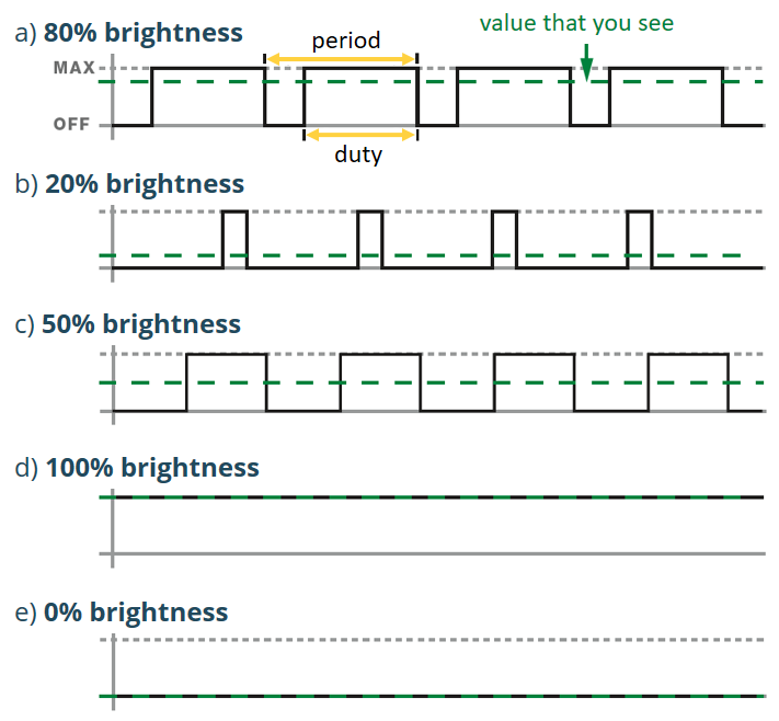
A duty cycle of 50 percent results in 50 percent LED brightness, a duty cycle of 0 means the LED is fully off, and a duty cycle of 100 means the LED is fully on. Changing the duty cycle is how you produce different levels of brightness.
analogWrite()
To produce a PWM signal on a given pin you use the following function:
analogWrite(pin, value);
pin: PWM may be used on pins 0 to 16 value: should be in range from 0 to PWMRANGE, which is 255 by default. When value is 0, PWM is disable on that pin. A value of 255 corresponds to 100% duty cycle You can change the PWM range by calling:
analogWriteRange(new_range);
By default, ESP8266 PWM frequency is 1kHz. You can change PWM frequency with:
analogWriteFreq(new_frequency);
Valid values are from 100Hz to 40000Hz.
ESP8266 NodeMCU Dim LED with PWM building a simple example that dims an LED so that I see how to use PWM in my projects. Parts needed:
- ESP8266 (read Best ESP8266 development boards)
- 5mm LED
- 330 Ohm resistor
- Breadboard
- Jumper wires
- Optional Oscilloscope If you’re using an ESP-01, you need an FTDI programmer or a Serial Adapter to upload code.
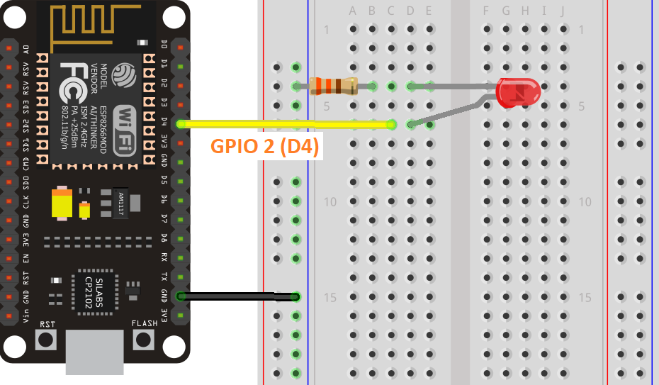
Schematic After uploading the code, wire an LED to the ESP8266 as shown in the following schematic diagram. Connecting the LED to GPIO 2.
ESP8266 NodeMCU PWM Code
Copy the code to your Arduino IDE and upload it to your ESP8266.
const int ledPin = 2;

void setup() {

}

void loop() {
  // increase the LED brightness
  for(int dutyCycle = 0; dutyCycle < 255; dutyCycle++){
    // changing the LED brightness with PWM
    analogWrite(ledPin, dutyCycle);
    delay(1);
  }

  // decrease the LED brightness
  for(int dutyCycle = 255; dutyCycle > 0; dutyCycle--){
    // changing the LED brightness with PWM
    analogWrite(ledPin, dutyCycle);
    delay(1);
  }
}
How the code works Continue reading this section to learn how the code works, or skip to the next section.
Start by defining the pin LED is attached to. In this case, LED is attached to GPIO 2 (D4).
const int ledPin = 2;
In the loop(), vary the duty cycle between 0 and 255 to increase the LED brightness.
for(int dutyCycle = 0; dutyCycle < 255; dutyCycle++){
  // changing the LED brightness with PWM
  analogWrite(ledPin, dutyCycle);
  delay(1);
}
And then, between 255 and 0 to decrease brightness.
for(int dutyCycle = 255; dutyCycle > 0; dutyCycle--){
  // changing the LED brightness with PWM
  analogWrite(ledPin, dutyCycle);
  delay(1);
}
Upload the Code In your Arduino IDE, go to Tools > Board and select your ESP8266 model
From Tools > Port ... select the COM port the ESP8266 is connected to.
After uploading your sketch, the LED connected to GPIO 2 should increase and decrease its brightness over time.
HERE INSERT A PICTURE OF THE CIRUIT WORKING

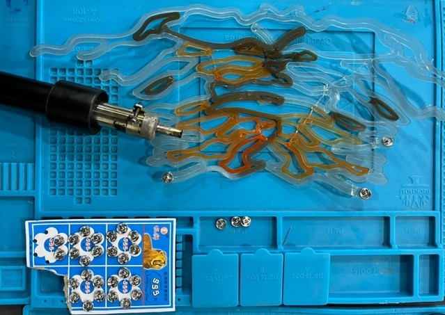
Initial 3D Printing
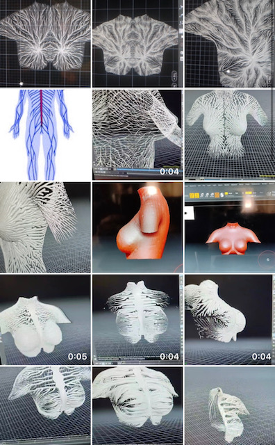
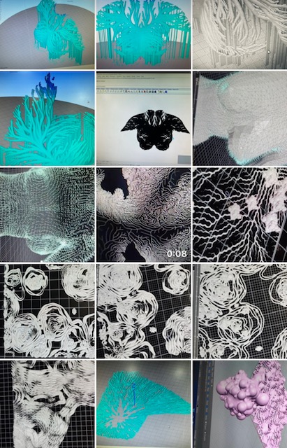
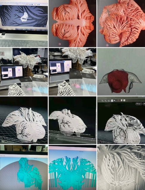
so I was trying to print one layer from the crystal branching geometry tracing so hoping I can bend it via the heat gun (so I was initially testing the idea of transforming 2D into 3D)
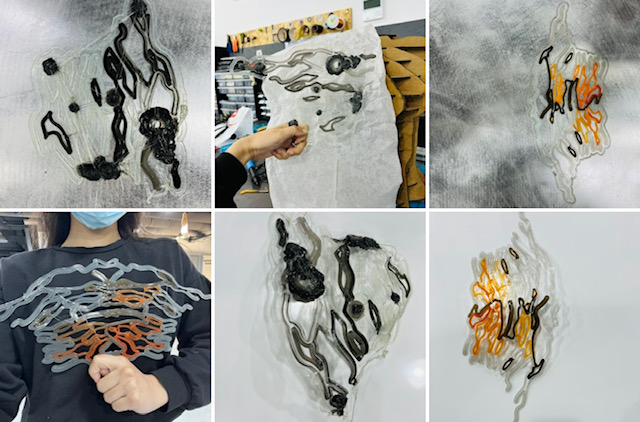
The main trick was to try having overlap of the geomtry or connected lines

Resources
ESP8266 NodeMCU PWM with Arduino IDE – Dim LED (Analog Output)