8. Open Source Hardware - From Fibers to Fabric
Group Project by Batoul AL-Rashdan, Haneen Jaafreh and Maryam Ibrahim at Techworks Digital Lab via Fabricademy .
| Name | Task |
|---|---|
| All | Watch all lectures and group tutorials with the the HILO Studio and entire team + read prepare the Pdfs + Files + BOM + Make sure all materials are there + replace missing items with available ( different sizes of beams and wool) + Hardware / Assembly + Documentation |
| Batoul | 3D Printing All parts + modify the design if needed to fit new size |
| Batoul and Haneen | Electronics |
| Mariam and Haneen | Wool preparation |
Research
This week we were introduced to the open-source hardware field and its potential/limits within the textile world. Explored some ways to use digital fabrication and open-source technology to build up an open-source machine for knitting, and weaving using different materials and within different settings.
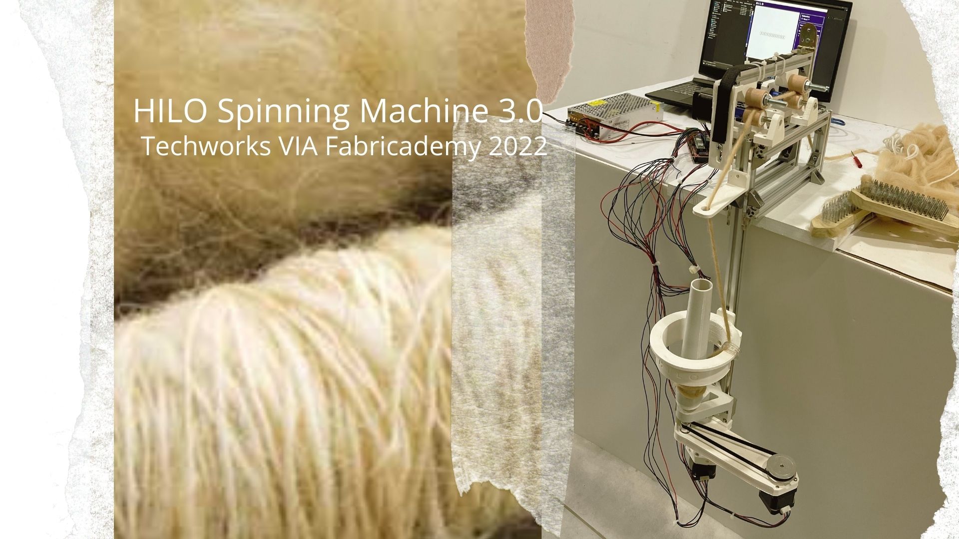
One exact open source project, in particular, was the HILO Studio Spinning Machine version 3.0. by Studio HILO, and allows users to produce their own customized yarn.
This Machine with its software can be used to spin small amounts of new fibers of your choice whether new or recycled. The software helps to design and plan the yarn digitally. The machine allows you to spin and twist yarn, Using different fibers (e.g. wool, flax, plastics). SIMPLE! PORTABLE!
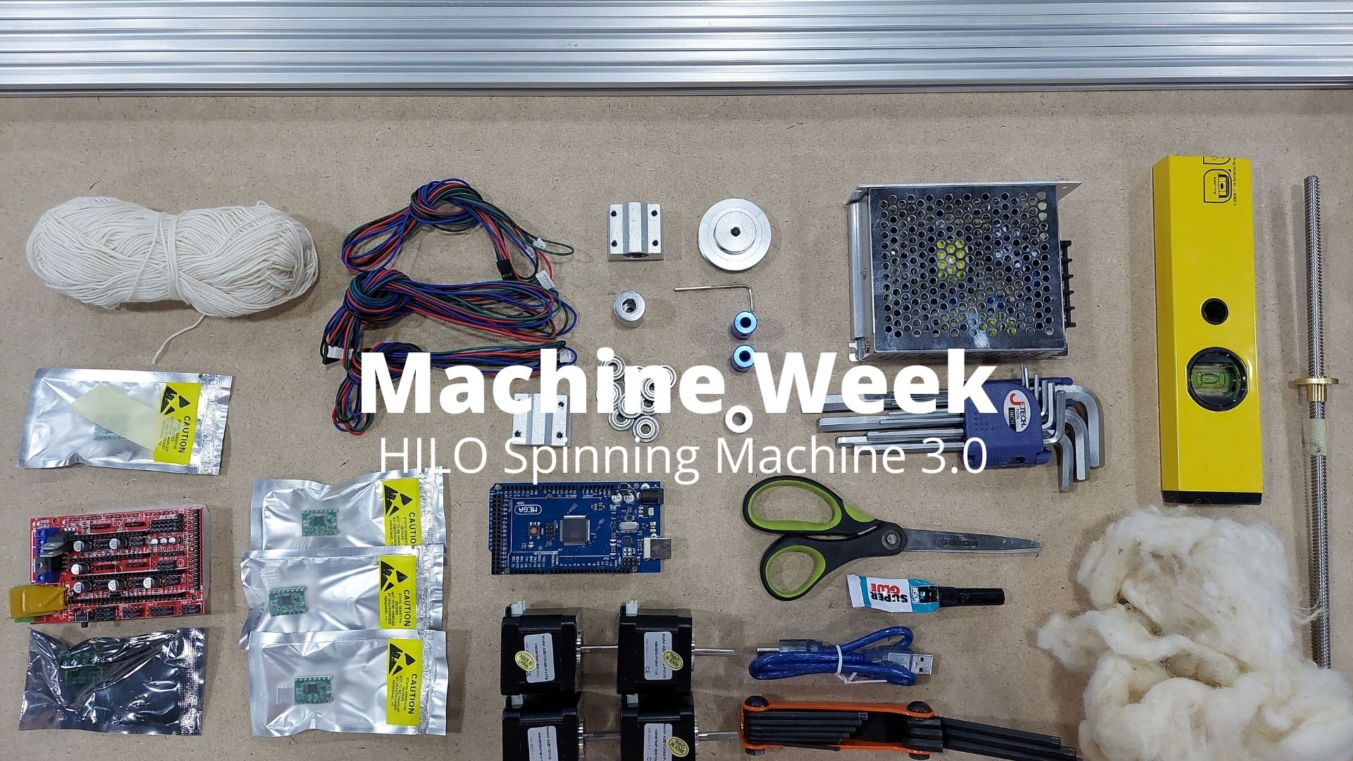
Fabrication
We were provided with files and documents explaining the process of building, calibrating, and soft wiring the machine. We modified a bit on the original design because of some challenges that arose along the way.
Our main issues were a bit of a difference in the available materials. Here is how it went:
- Markbeams
The mark beams available were 20 x 20 mm instead of the 30 x 30 mm that were listed.
This resulted in 2 main changes :
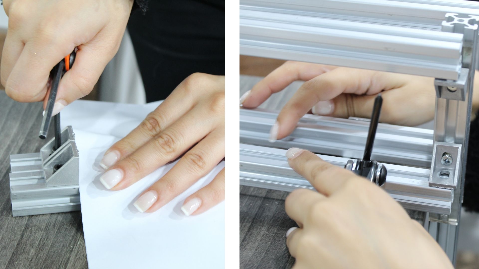
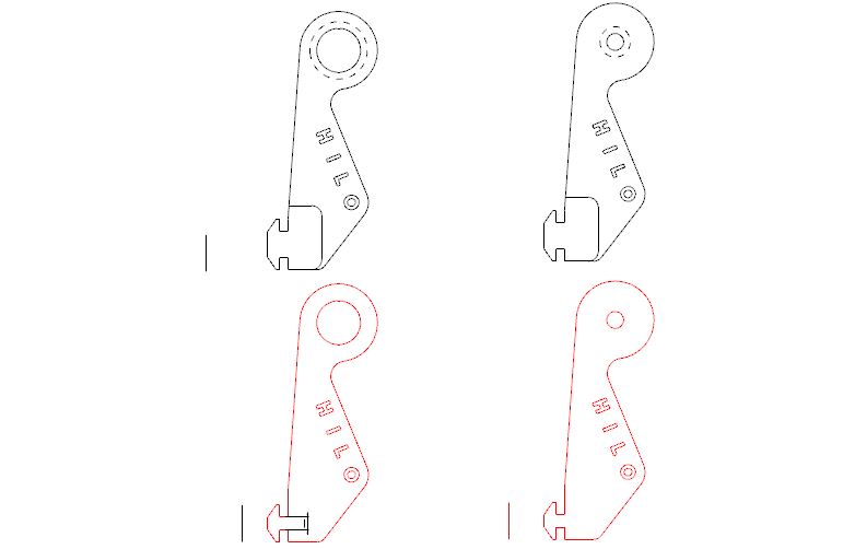
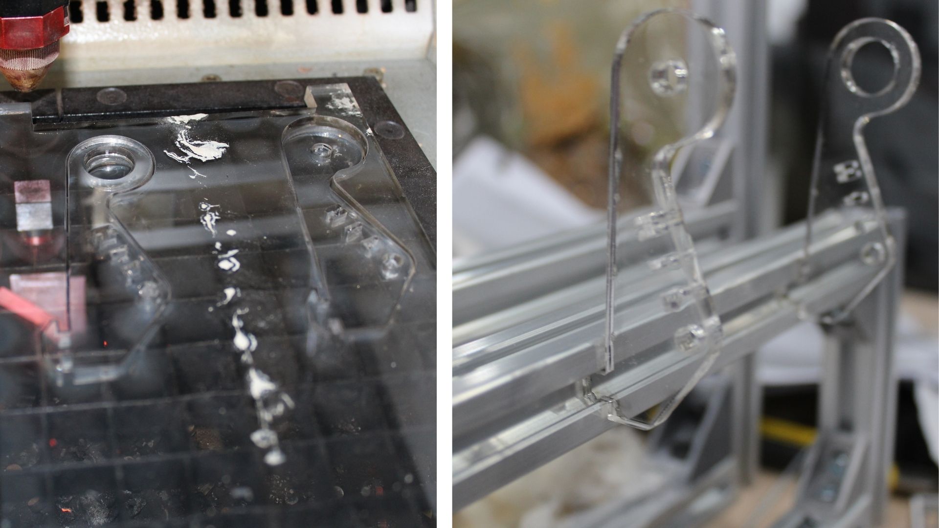
First, the structure using the 20 x 20 mm markbeams would result in a change of dimensions in the structure. Therefore, we used 2 laser cut acrylic sheets to compensate for the width for the spinning wheels to fit properly.
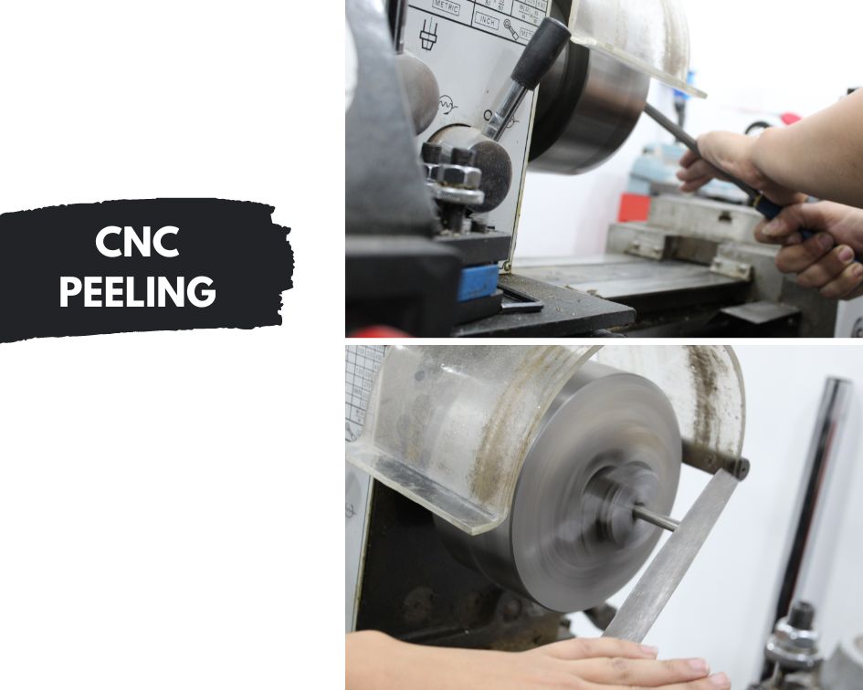
Second, some 3d printed parts fit directly into the markbeam which required a change in the dimensions of the connection parts in the 3d models. After printing some 3d files we found out that the connection parts were larger than their designated space in the markbeams, we ended up milling and cutting the connection parts to fit in the available markbeams.
- The rotating belt
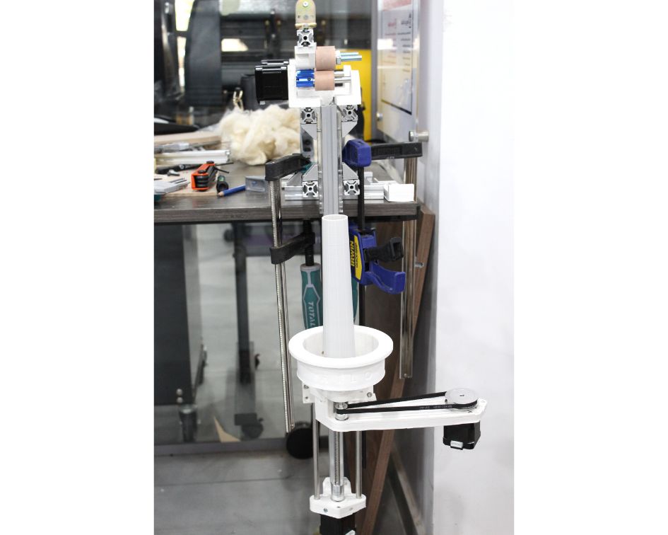
The only available belt was a 400 mm in length in comparison to the designed belt which is 150 mm. A great difference that results in a designed 3d printed base for the belt and motor for which we worked on using Autocad Fusion. In order to do that, we laser cut a wood sheet template, tested it, and then used it as a print palette to mark the motor placement and its screw holes. We adjusted the 3d printed file and 3d printed it.
It made the machine a bit heavier on one side so having it fixed on a plate balanced it.
Hardware
The Process is divided into 6 main parts that we were working on simultaneously
Structure
-
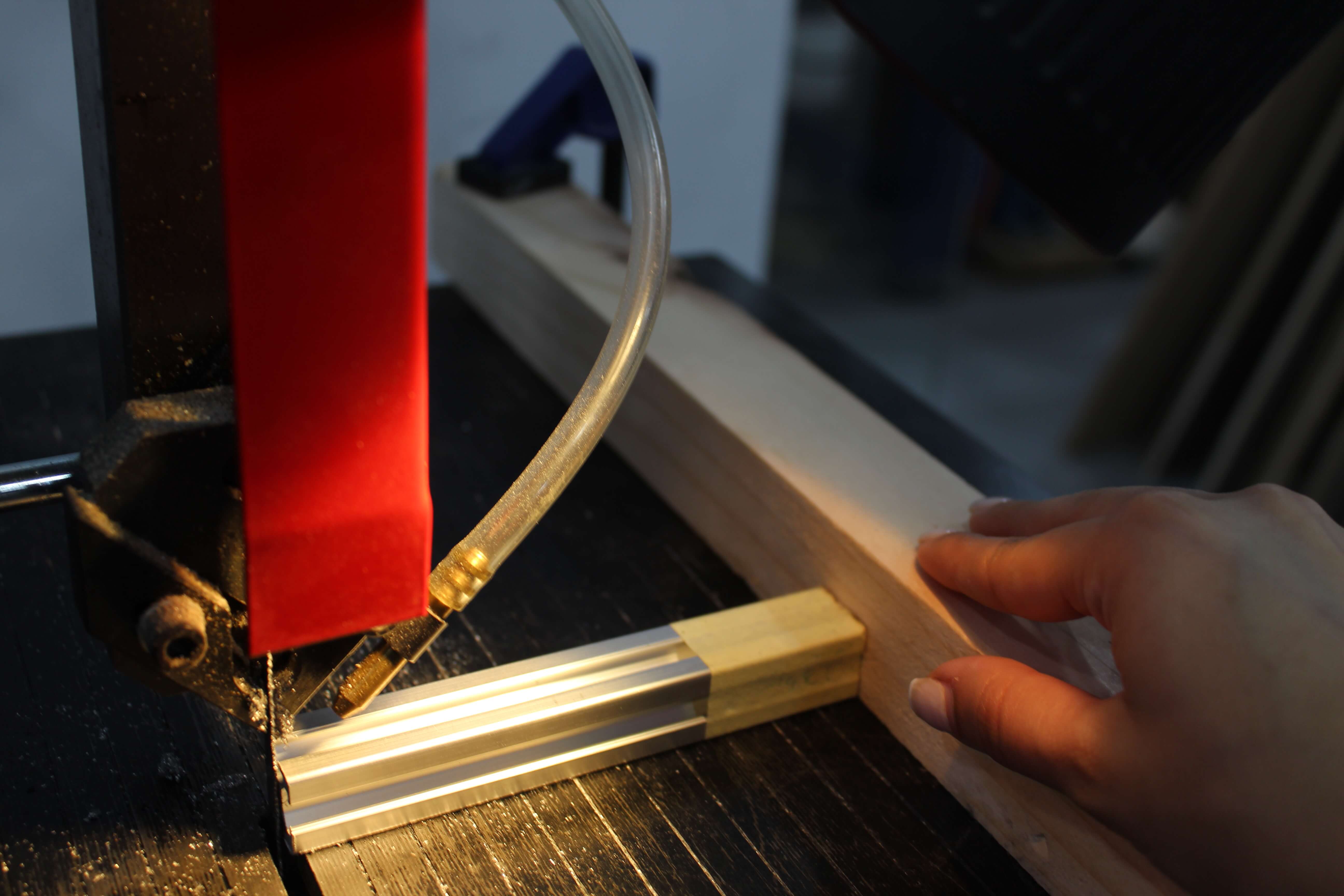
We cut the markbeams into the provided length using sawing machine
-
We laser cut the acrylic sheet to compensate width
Laser settings:
Power: 90.0
Frequency: 10000
Speed: 0.4
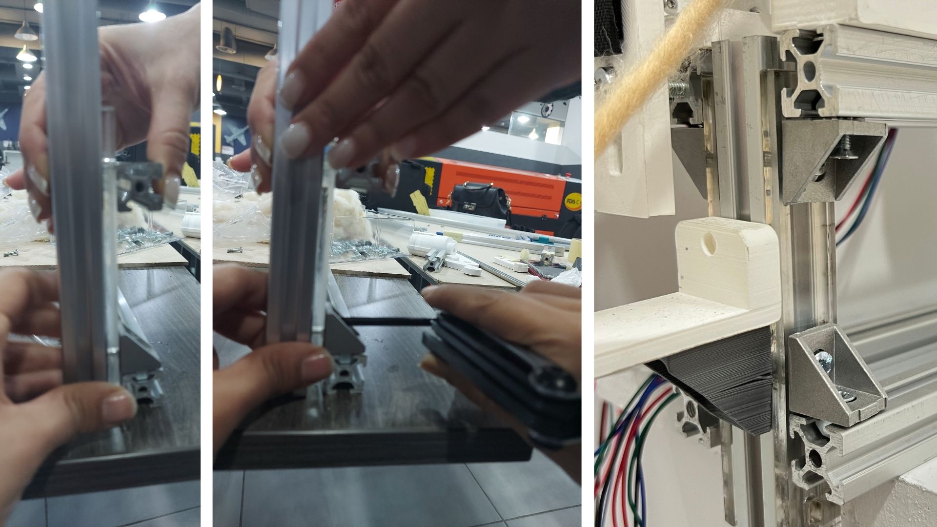
- Using angles and screws we fixed the main structure. The screws had to be a different length because we were using different markbeams
-
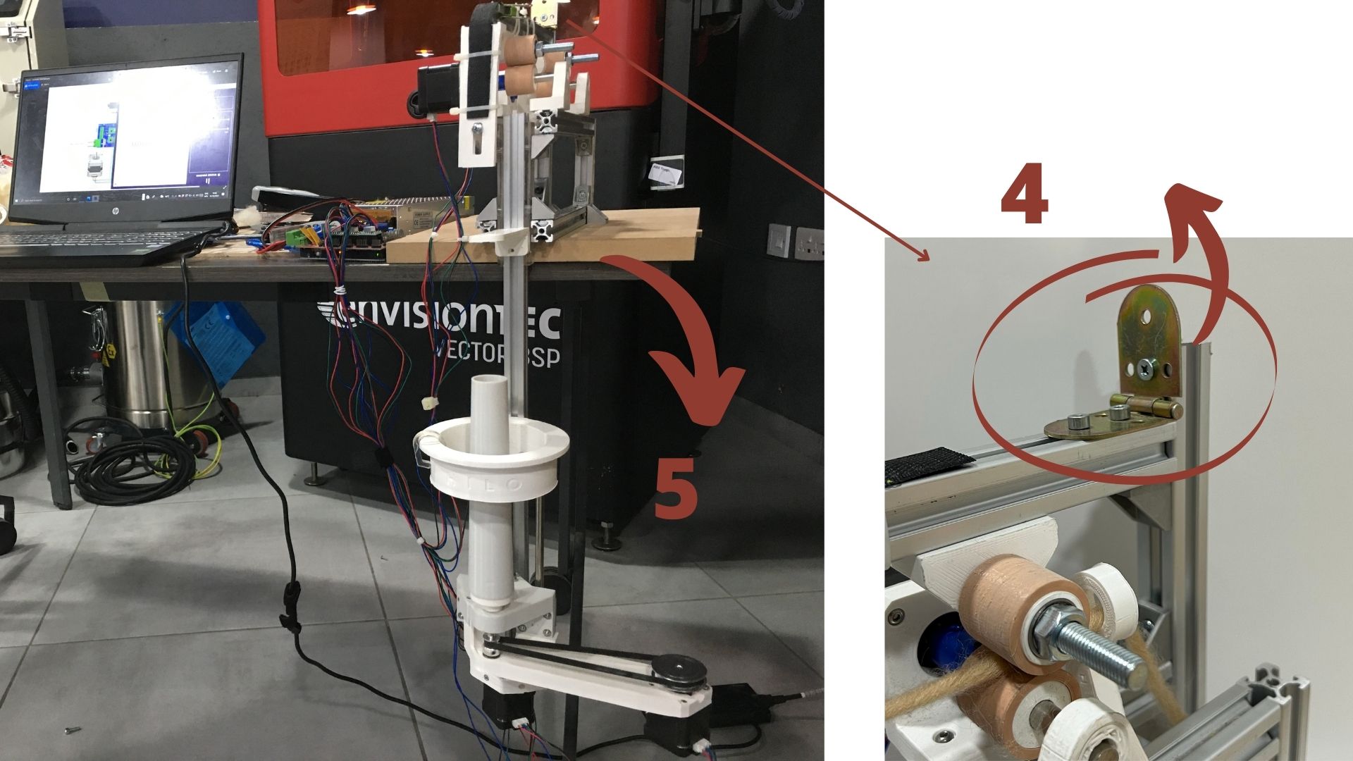
The rotating beam on a hinge was assembled later on for a manual fitting because dimensions changed due to using 20 x 20 markbeams
-
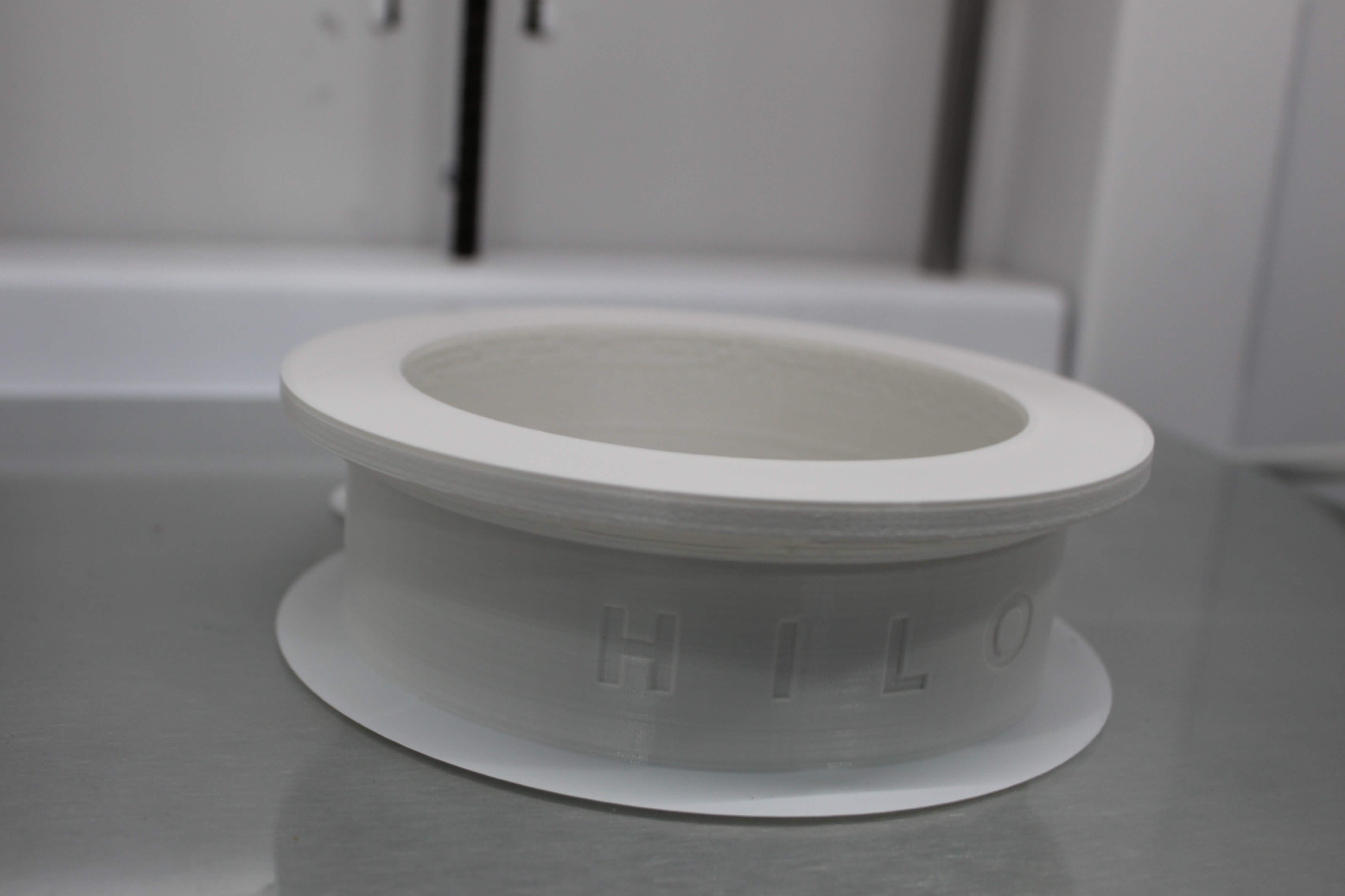
The base was first made using mark beams. However, it was not balanced and we used a wood plate like the picture (here we used white painted 4cm MDF board as seen in this picture)
Drive Wheels Section
-
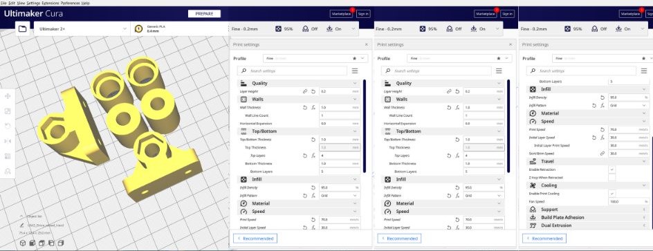
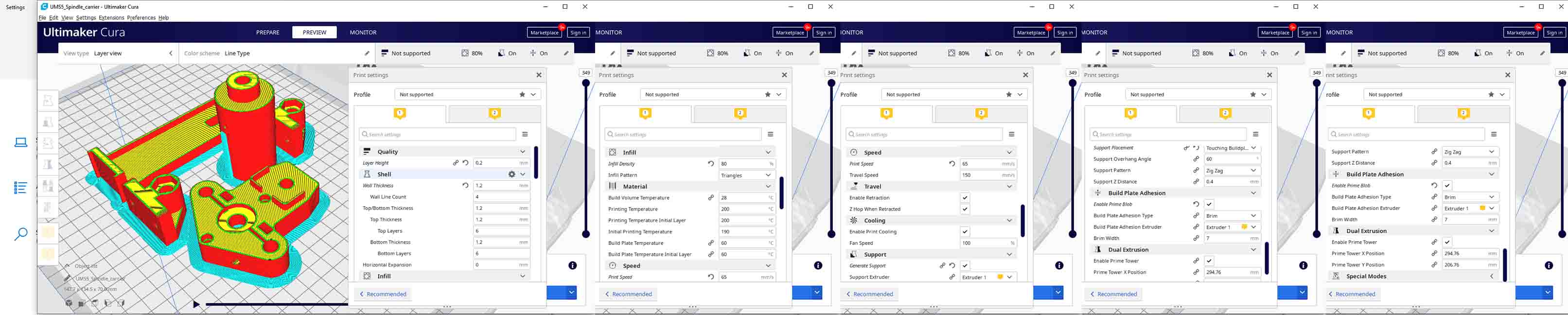
Printed the Motor holders and Motor axel mount files using the following settings:
-
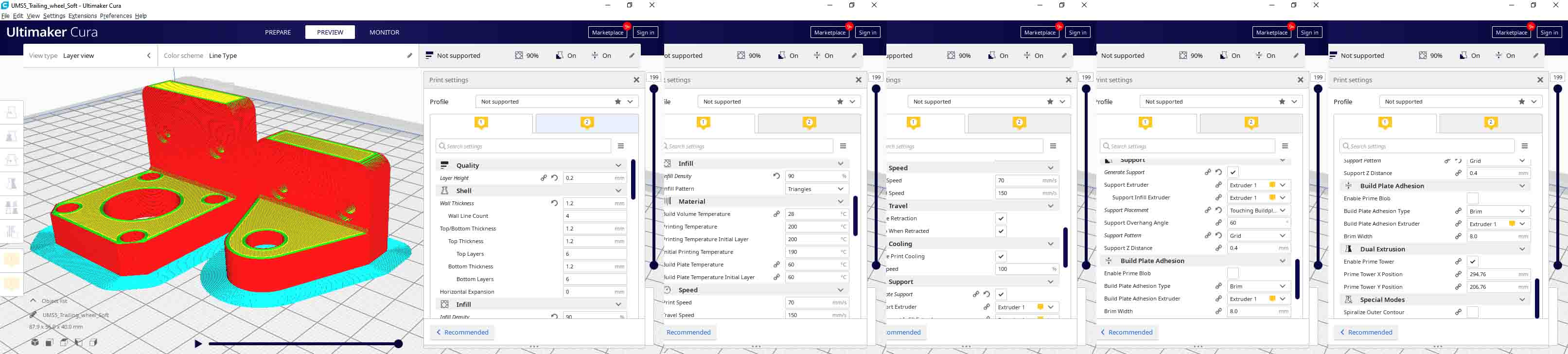
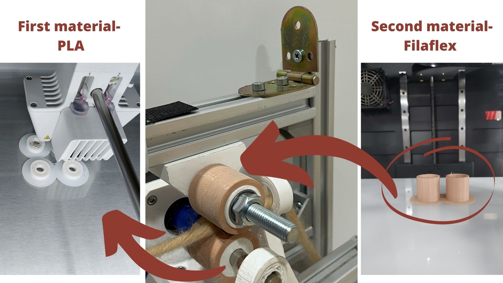
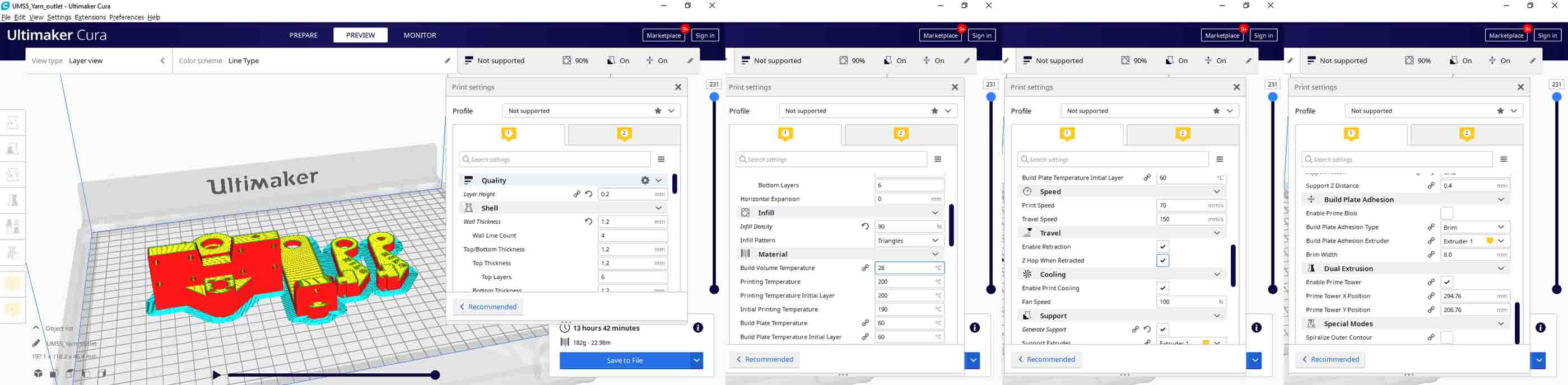
Printed the drive wheels and the trailing wheels in two phases as they were made of two materials PLA and TPU PLA and using the following settings
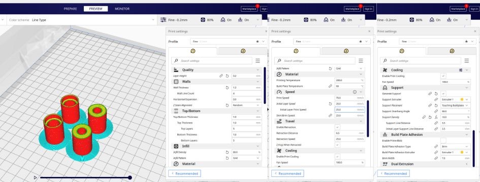
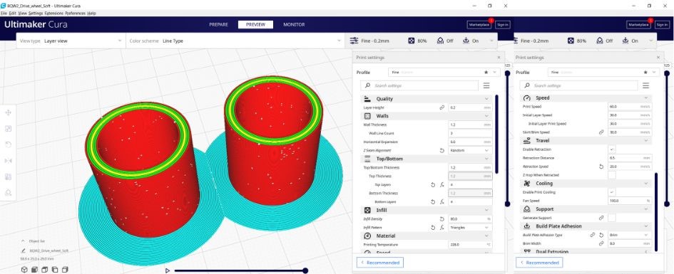
as you see most important from the setting to remember from shells/walls -> Z seam alignment -> random (from the drop down menu)
-
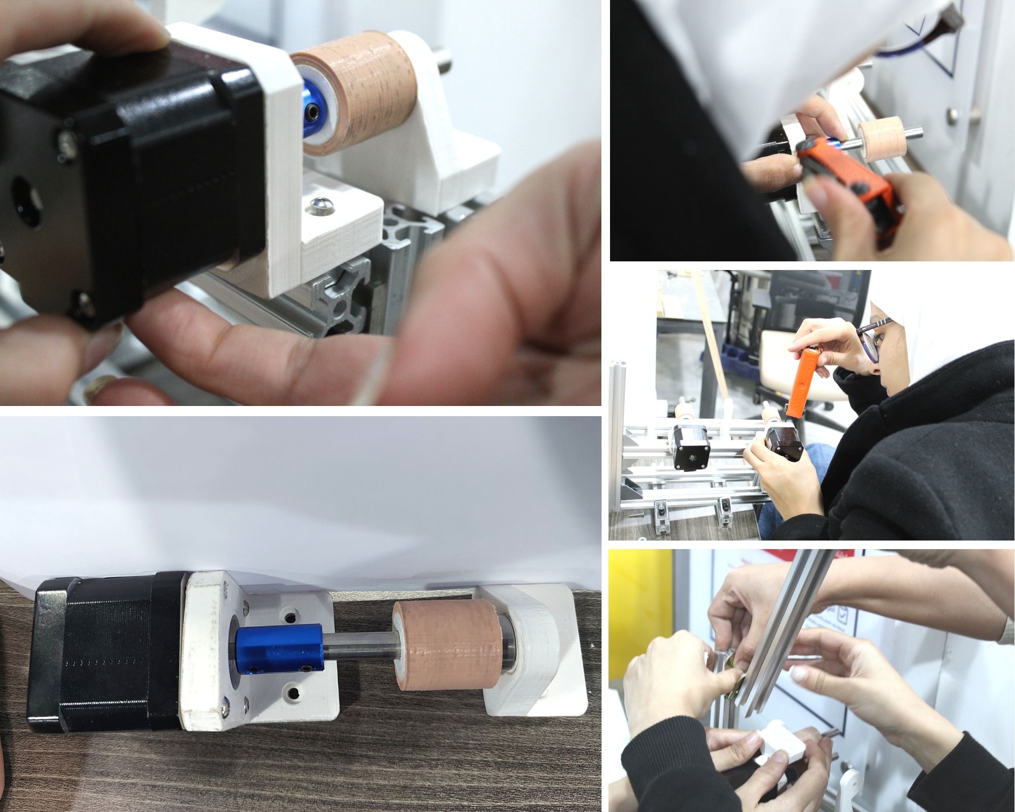
Connected the motor to the 3d printed motor holder
-
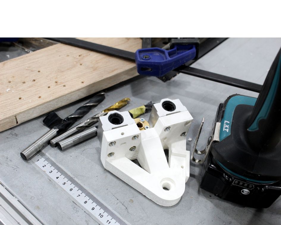
Cut the 8mm metal bar using the bandsaw machine and used the milling machine to smooth the edges
-
Connected the motor to the 6 cm in length metal bar using coupling
-
Put the Drive wheel in place (we didn't use glues as the fit was extremely tight ) and then added a coupling
-
Repeated that process as we need two items not one and fixed on structure as part of the final assembly section.
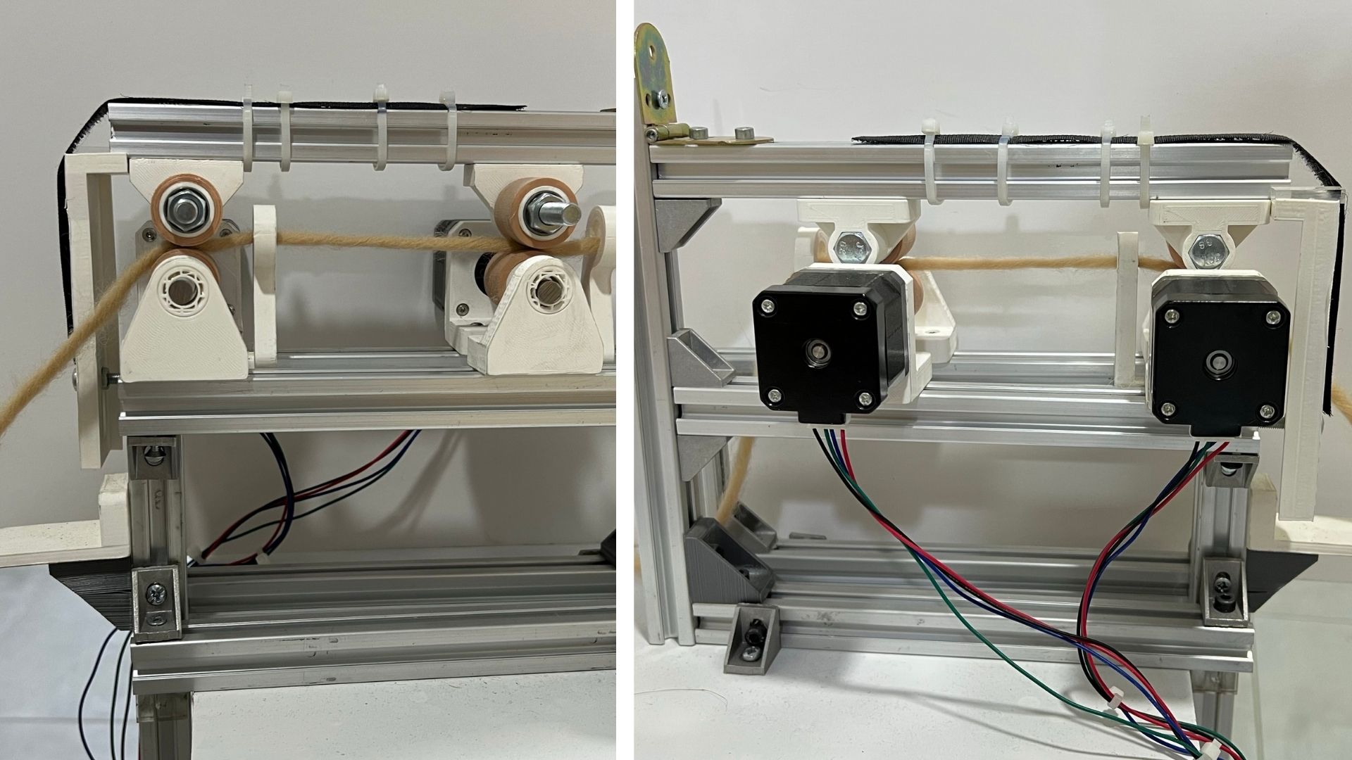
Trailing Wheels
-
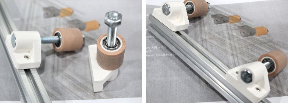
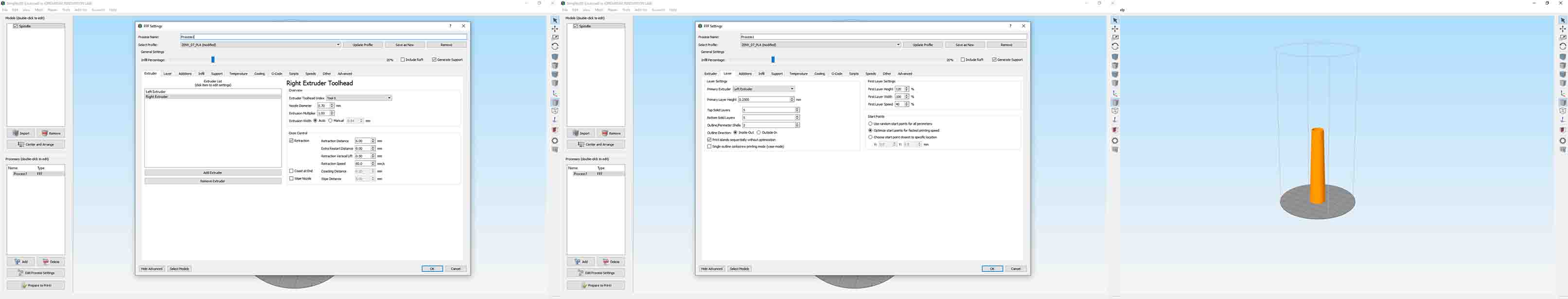
We already 3d printed the trailing wheel with the driving wheels using PLA and TPU and we3d printed the trailing wheels holders using these settings
We assembled the two parts together ready to be fixed using the hexagon screw
-
We couldn't find an M 8 x 80 hexagon screw that was two-thirds smooth, a third threaded. However, we found a fully threaded one. We used filing tools to smooth parts of the hexagon screw
-
We fit the hexagon screw to the Axle holder
-
Attached the wheel to the screw and glued it
-
Tightened the hexagon nut at the end of the screw
-
Fixed the entire thing the rotating markbeam
Spindle Platform and Elevator
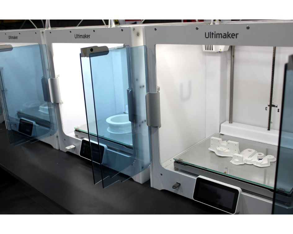
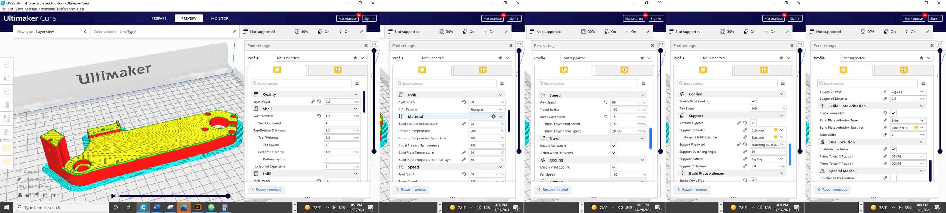
We 3d Printed the main parts seen on the far left in the pictures below
Part A
We fixed the linear bearings to the 3d printed files along with placing the Trapezoidal screw nut
Platform B
The only available belt was a 400 mm in length in comparison to the designed belt which is 150 mm. A great difference that results in a designed 3d printed base for the belt and motor for which we worked on using Autocad Fusion. In order to do that, we laser cut a wood sheet template, tested it and then used it as a print palette to mark the motor placement and its screw holes.
We adjusted the 3d printed file and 3d printed it.
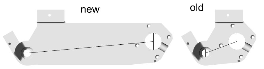
Here is the final 3d file
After printing, we placed the motor, bearings, spacers, the pulley teeth and the cut metal bar based on the instruction provided.
then connected the two platforms together and added the spline holder.
Now for the elevator, We fixed the motor to the elevator lower 3d printed part, added the guide rods and motor coupling and then the spindle.
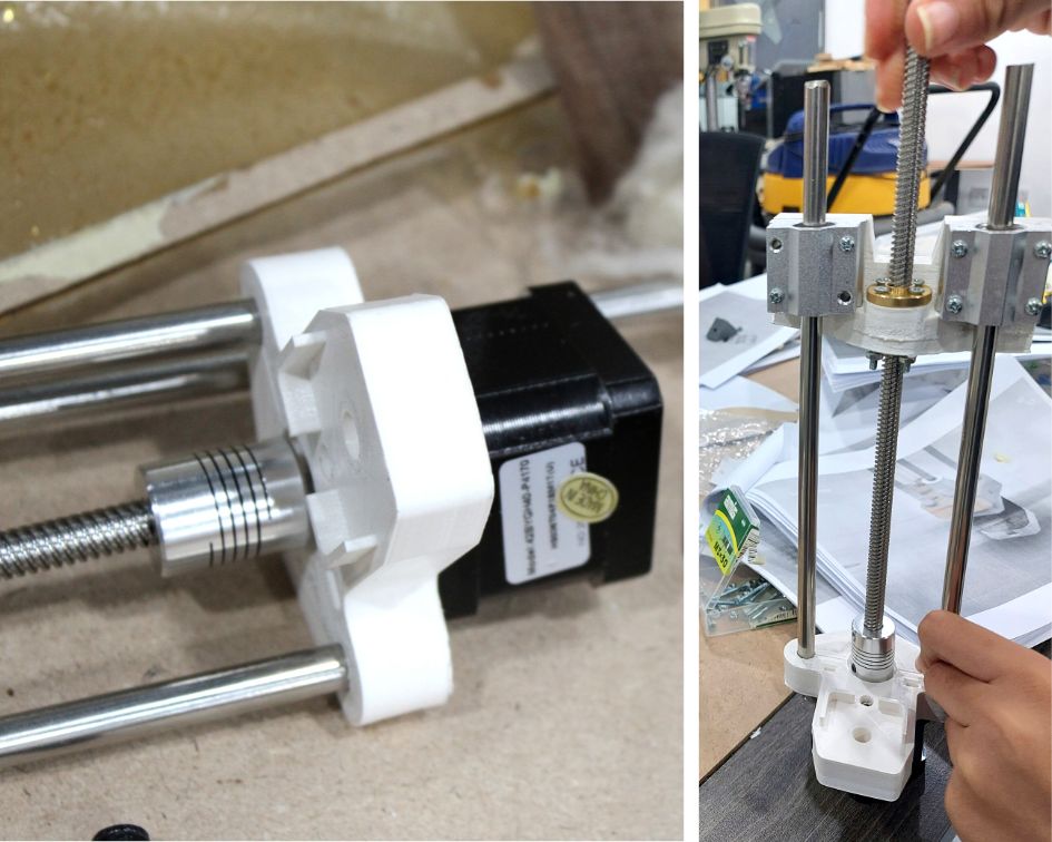
Now we add all the pieces together for the final assembly
We also edited on some additional files like these parts that guide the wool into the wheels
Final Assembly
Electronics Hardware
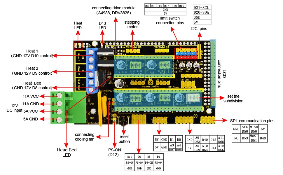
- Glueing the Heat Sink to each Driver Modules
- Connecting the Driver Modules to RAMPS 1.4
- Connecting the RAMPS board to the Arduino Mega 2560 board
- Connecting the cables to the Stepper Motors based on the diagram you see below
- Connecting the Stepper Motors to the Board
- Connecting the power supply to the RAMPS 1.4 Board
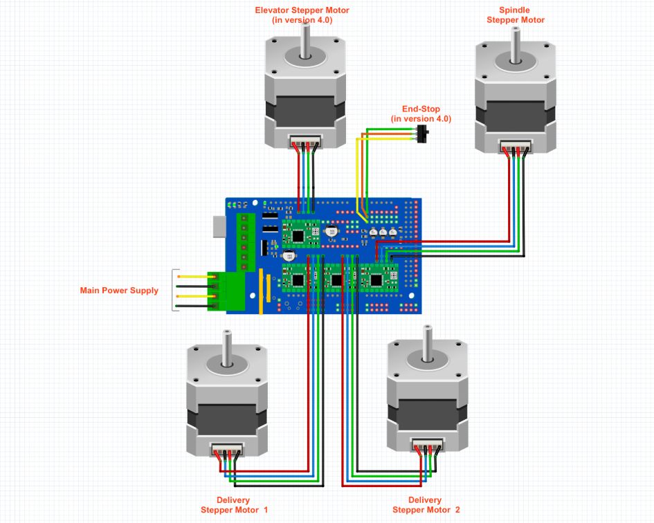
orientation
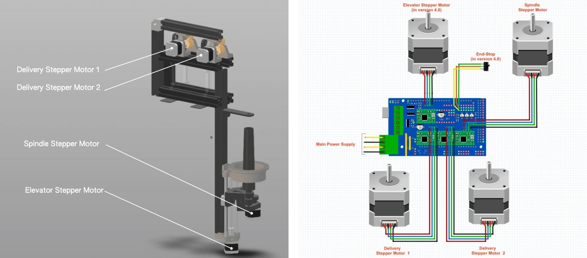
These images along with a detailed instruction document were provided by the Hilo Studio.
Calibration
Using this Youtube video and following the instructions We calibrated and adjusted the Stepper Motor Driver.
Since we are using Driver Module A4988, we have the current resistors to b R100.
Using this online SMD resistor code Calculator we get 0.1 Ω.
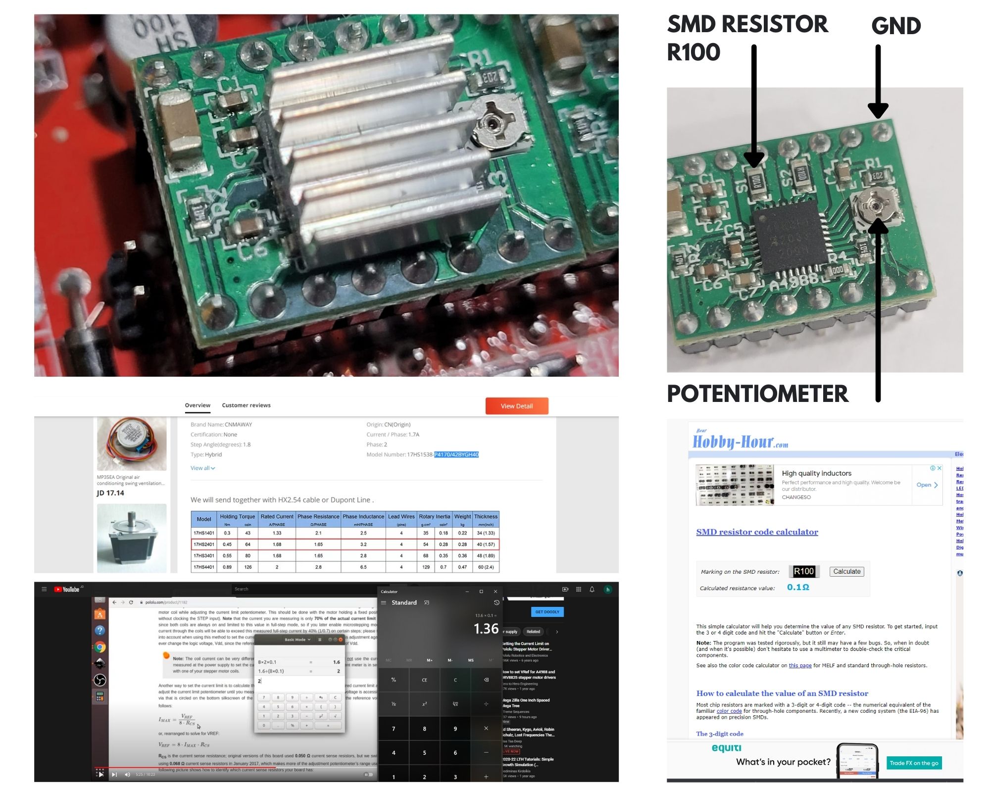
Calculating
VREF = 8 * IMAX * RCS

IMAX = 1.7 based on Data sheet
RCS = 0.1 Ω based on

VREF = 8 * 1.7 * .1  =  1.36
Then I hooked a screwdriver to the multimeter (+), and hooked the COM prob of the multimeter to the ground in the RAMPS. Then used a power supply to turn it on then placed the screwdriver and started rotating the potentiometer of the driver to get a reading of 1.36 and doing the same for the rest of Driver modules.
Software
Arduino
In order to upload the software to arduino we did the following :
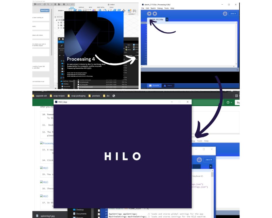
- Downloaded all HILLO app files
- Downloaded program processing
- Connected the USB cable in the Arduino Mega Board to the Computer
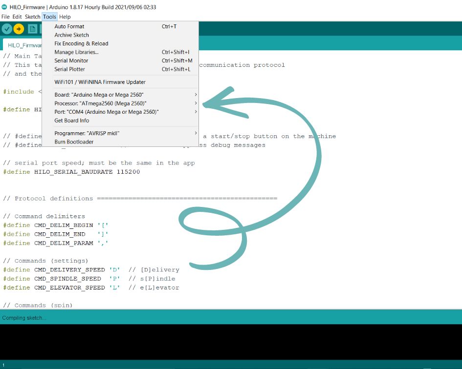
- Openned the HILO Firmware through arduino which is located in the folder HILO_App by double-clicking CommandParser.ino
- From tools we selected the following :
- Arduino Board → Arduino Mega or Mega 2560
- Port USB modem
- Programer AVRISP mkll
- Uploaded the Software to the Arduino
Now the Arduino is set and we don't have to do this again unless we changed the arduino or if another software was uploaded to it.
Processing
-
We opened the Hilo app by double-clicking on any file in the HILO_App folder
-
the processing software opened then directly the HILO_App software opened
-
By Pressing the play button, the app interface opened.
Interface
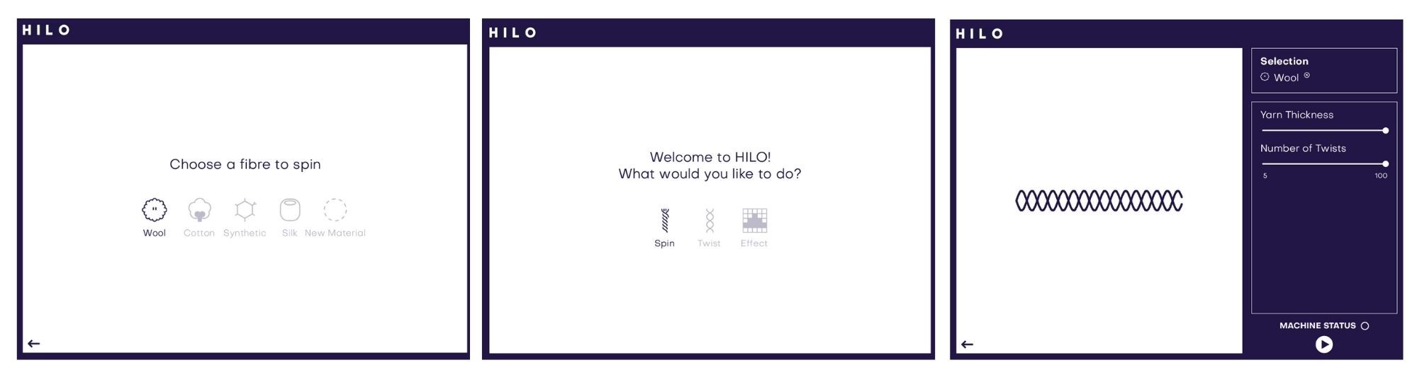
The software helps to design and plan the yarn digitally – for weaving or knitting textiles. It controls the thickness and amount of twist of spun yarn.
Connecting Arduino to the computer and power and then opening the file HILO App from HILO App folder.
- Click on the play button to open the HILO App
- Select what to do with the fibers( Spin or Twist )
- Choose the material of the fibers to spin (wool in our case)
- You can adjust the thickness and twist for our yarn by moving the bars on the right side.
Then just press PLAY.
Testing
Preparing Wool
Since our fiber of choice is wool here is the process we used to prepare it :
-
We brought wool from a village in Jordan famous for raising livestock.
-
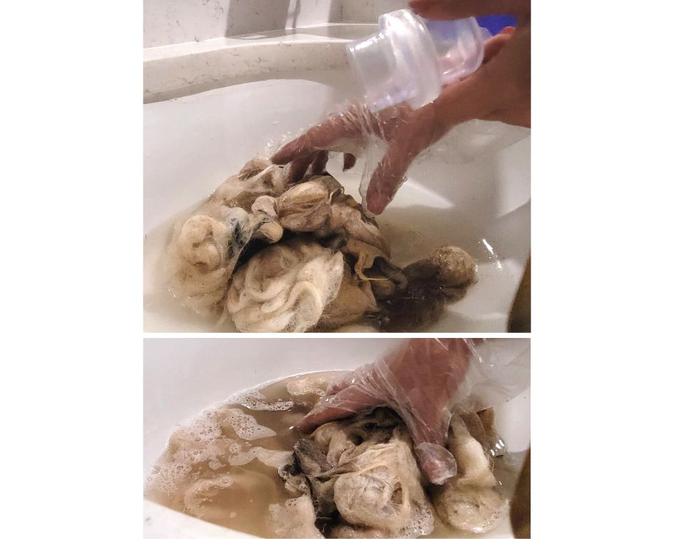
Cleaning and scouring
Wool taken directly from the sheep is called "raw" or "grease wool." It contains sand, dirt, grease, and more. To remove these contaminants, the wool is scoured in a series of baths containing water, and soap. Then squeezed the water out and left to dry. It was a difficult process because of the smell and how dirty it was. It got cleaner but still not that clean.
- Carding
After that, the fibers are supposed to pass through a series of metal teeth that straighten and blend into slivers. Carding also removes residual dirt and other matter left in the fibers. Carded wool intended for worsted yarn is put through gilling and combing, two procedures that remove short fibers and place the longer fibers parallel to each other. From there, the sleeker slivers are compacted and thinned through a process called drawing.
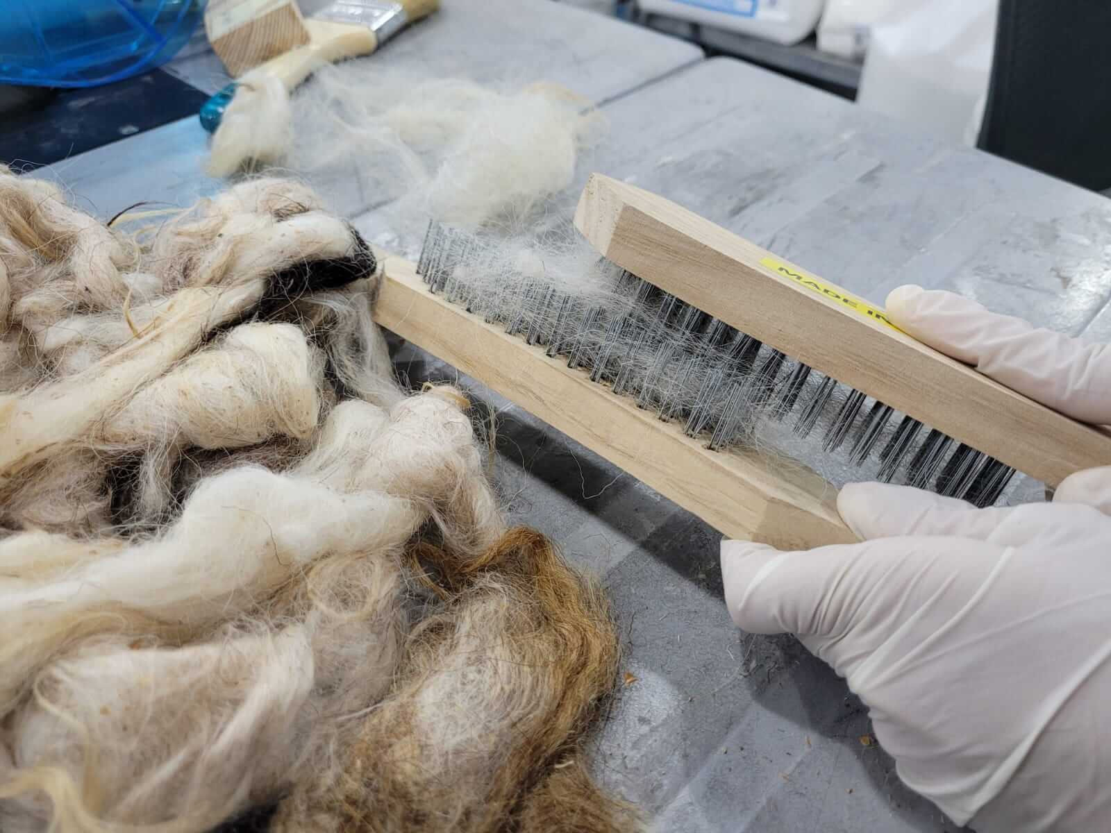
We could not find metal teeth combs suited for wool in the local market, and we bought two similar combs from the hardware store to finish the job. However, we didn't get much success with this process, as the wool kept getting cut every now and then. Therefore, we bought natural wool that has been washed, combed, and can be rolled up without cutting.
Final
Downloads
You can download the edited files here: