13. Skin Electronics
Skin electronics are electronic devices which are attached to the surface of the body and enable the wearer to interact with the digital world. Sensors can be applied directly to a person’s skin and to be hidden on the body. This can be extremely beneficial for taking accurate measurements of body parameters or tracking movement.
References & Inspiration
| Skin interfaces | electrominescent ink: glowing when a current passes through it | Touchpad fabric |
Exploration of different techniques
3*3 piezoresistive paper matrix
- Alligator clips
- Velostat
- Copper tappe
- Papper
- Arduino UNO
- Breadboard
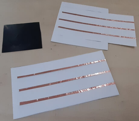
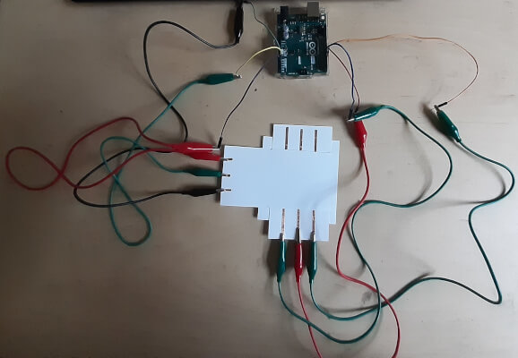
Making a 3x3 paper matrix. To make it, we use velostat, which is a pressure sensitive material. Two pieces of paper are placed perpendicular to each other with three thin strips of copper tape and a strip of velostat between the two papers. The intersection of these 6 strips allows 9 variable resistances to be measured.
| Matrix composants | Circuit | Video |
|---|---|---|
 |
 |
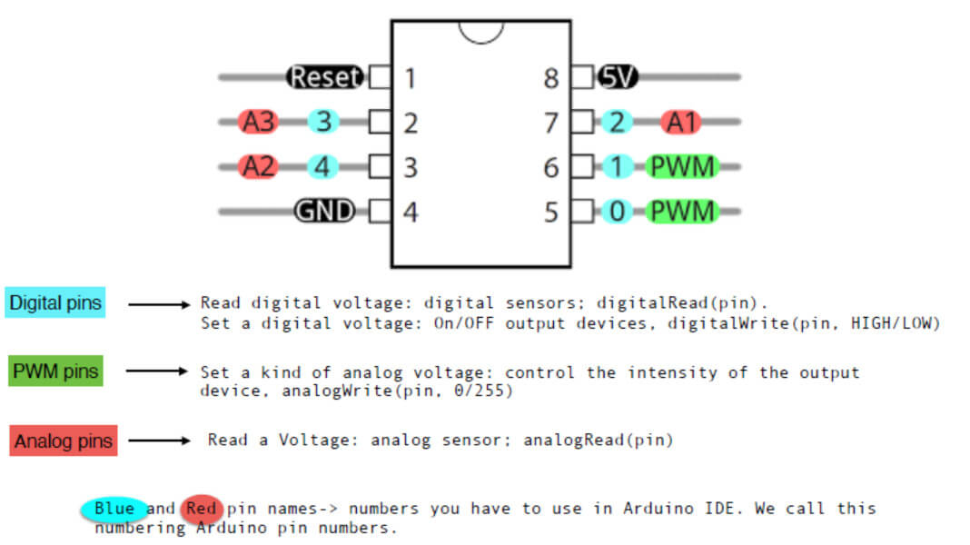
ATtiny
- ATtiny85
- 10uF electrolytic capacitor
- 220 ohm resistor
- LED
- Wire
- Arduino UNO
- Breadboard
| Step | picture / Video |
|---|---|
| ATtiny circuit | 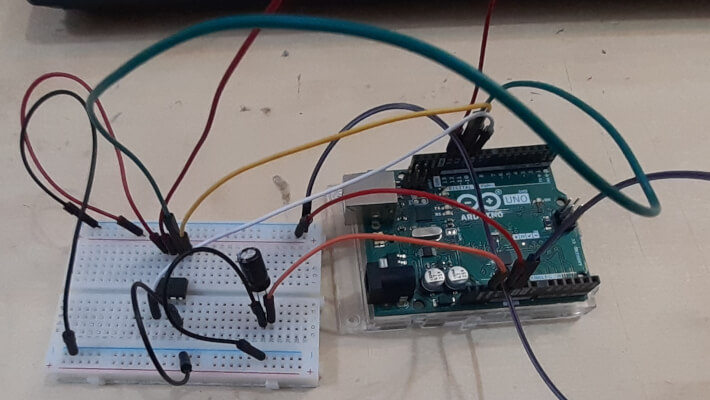 |
| attiny_led with Arduino | |
| attiny_led without Arduino | |
| attiny with digital sensor |
  /* Emma Pareschi, Nov 2019
   *
   *  the led connected to pin 1. it blinks
   */
   int led_pin = 1;  //pin of the Led

  void setup() {
  // put your setup code here, to run once:
  pinMode(led_pin, OUTPUT);   // set the pin 1 as OUTPUT

   }

  void loop() {
  // put your main code here, to run repeatedly:
  digitalWrite(led_pin, HIGH);      //turn the Led ON
  delay(1000);                      //wait for a second
  digitalWrite(led_pin, LOW);       //turn the Led OFF
  delay(1000);                      //wait for a second
    }
    }
   /*Emma Pareschi 2020
   the Led turns on when the digital sensor is triggered
   */
   // this constant won't change:
  int sw_pin = 4;    // the pin that the pushbutton is attached to
  int led_pin = 1;   //pin of the led

   // Variables will change:
   int sw_status = 0;         // current state of the button

   void setup() {
   // initialize input and output pins:
   pinMode(sw_pin, INPUT_PULLUP);
   pinMode(led_pin, OUTPUT);
   }

   void loop() {

   // read the pushbutton input pin:
   sw_status = digitalRead(sw_pin);

   // compare the switch status to its previous state
   if (sw_status == LOW) {   //if the sw is pressed
    digitalWrite(led_pin, HIGH);   //turn on the led (5V)
   } else {        //if the sw is not pressed
    digitalWrite(led_pin, LOW);   //turn off the Led (0V)
   }
   }
Capacitive sensor
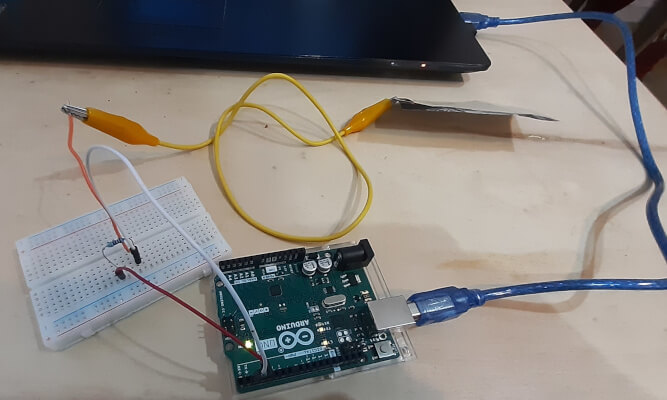
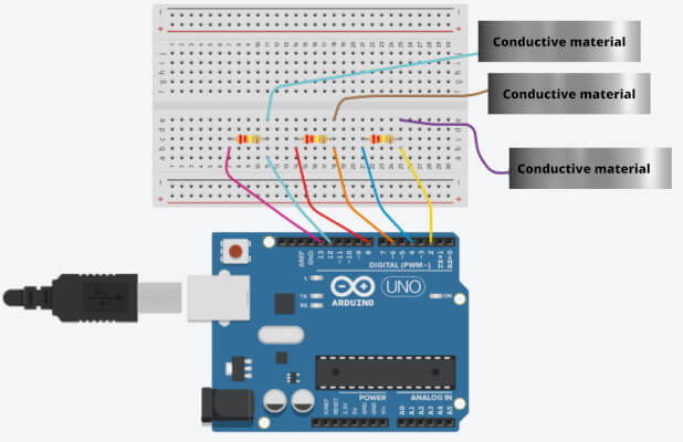
A capacitive sensor can detect the presence of an hand. It can be a foil of conductive objet or a wire.
- Aluminium folder
- Wire
- Arduino UNO
- Breadboard
| Step | Circuit | Video |
|---|---|---|
| 1 Capacitive sensor | 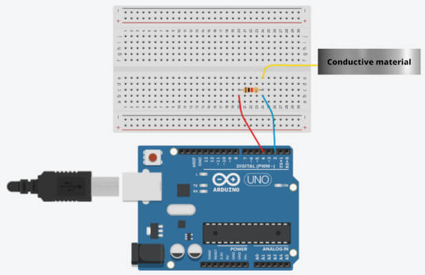 |
 |
| Serial monitor 2 capacitive sensors | 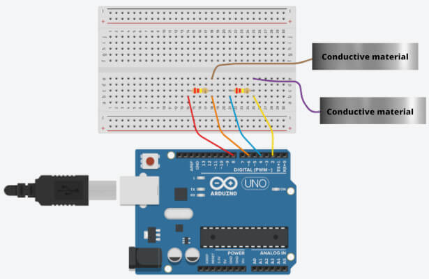 |
|
| 2 leds 2 capacitive sensors | 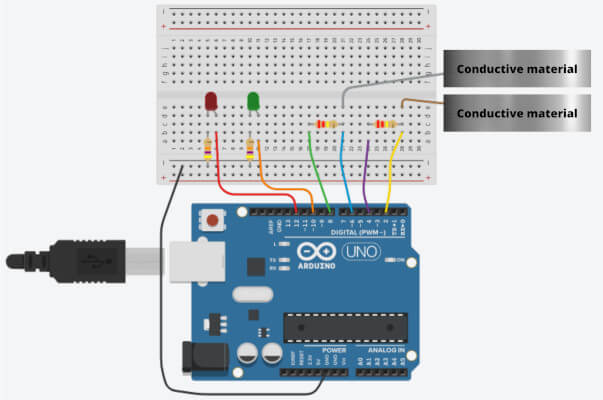 |
  #include <CapacitiveSensor.h>

 /*
 * Modified example from CapitiveSense Library Demo Sketch (Paul Badger 2008)
 * Uses a high value resistor e.g. 10M between send pin and receive pin
 * Resistor effects sensitivity, experiment with values, 50K - 50M. Larger resistor values yield larger sensor values.
 * Receive pin is the sensor pin - try different amounts of foil/metal on this pin
 */

 CapacitiveSensor   cs_4_2 = CapacitiveSensor(4,2);   // 300K resistor between pins 4 & 2, pin 2 is sensor pin, add a wire or foil if desired

 long total1;  //definition

 void setup()
 {
   cs_4_2.set_CS_AutocaL_Millis(0xFFFFFFFF);  // turn off autocalibrate on channel 1 - just as an example
   Serial.begin(9600);  //open communication
 }

 void loop()
 {
    long total1 =  cs_4_2.capacitiveSensor(10);
    Serial.println(total1);                  // print sensor output 1
    delay(100);
 }
 #include <CapacitiveSensor.h>

 CapacitiveSensor   cs_4_2 = CapacitiveSensor(4,2);        // 10M resistor between pins 4 & 2, pin 2 is sensor pin, add a wire and or foil if desired
 CapacitiveSensor   cs_8_6 = CapacitiveSensor(8,6);        // 10M resistor between pins 8 & 6, pin 6 is sensor pin, add a wire and or foil

 void setup()
 {
   Serial.begin(9600);
 }

 void loop()
 {
    long total1 =  cs_4_2.capacitiveSensor(30);
    long total2 =  cs_8_6.capacitiveSensor(30);

    Serial.print(total1);         // print sensor output 1
    Serial.print("\t");
    Serial.println(total2);       // print sensor output 2
    delay(100);                   // arbitrary delay to limit data to serial port

 }
 #include <CapacitiveSensor.h>

 CapacitiveSensor   cs_4_2 = CapacitiveSensor(4,2);        // 10M resistor between pins 4 & 2, pin 2 is  sensor pin, add a wire and or foil if desired
 CapacitiveSensor   cs_8_6 = CapacitiveSensor(8,6);        // 10M resistor between pins 8 & 6, pin 6 is sensor pin, add a wire and or foil

 int thr = 100; //threshold

 int led1_pin = 10;
 int led2_pin = 12;

  void setup()
 {
   Serial.begin(9600);
    pinMode(led1_pin, OUTPUT);
    pinMode(led2_pin, OUTPUT);
 }

 void loop()
 {
    long total1 =  cs_4_2.capacitiveSensor(30);
    long total2 =  cs_8_6.capacitiveSensor(30);

    Serial.print(total1);          // print sensor output 1
    Serial.print(" ");
    Serial.println(total2);        // print sensor output 2
    delay(10);                     // arbitrary delay to limit data to serial port

  if(total1 > thr & total2 < thr){

    digitalWrite(led1_pin, HIGH);
    digitalWrite(led2_pin, LOW);

  } else if ( total1 < thr & total2 > thr){

    digitalWrite(led1_pin, LOW);
    digitalWrite(led2_pin, HIGH);

  } else if( total1 > thr & total2 > thr){

    digitalWrite(led1_pin, LOW);
    digitalWrite(led2_pin, LOW);

  } else {

    digitalWrite(led1_pin, HIGH);
    digitalWrite(led2_pin, HIGH);
    }
  }
Project: interactive tatoo
| Step | picture / Video |
|---|---|
| Half-cutting with ScanNCut SDX1250 Brother (pressure:-2, speed:4, half cut: ON) | 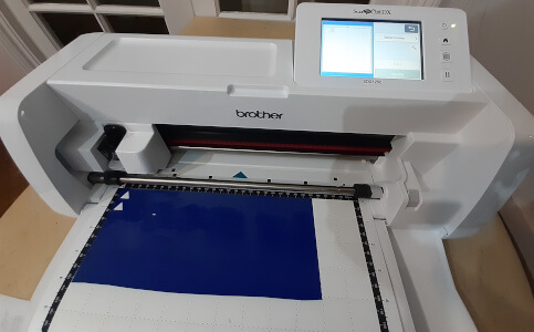 |
| Selection of the pattern directly on the machine. I chose a star that I replicated 3 times in 3 different sizes and orientations. Each star is a capacitive touch button. | 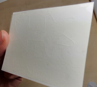 |
| Plastic stars removing | |
| Gold leaf (conductive material) deposition on the exposed sticky part. Place conductive wire on the stars. I added copper tape to reinforce the connection. These reinforcements will be invisible as they will be on the skin side. | |
| Insulation with skin. Layer of nonconductive material adds between conductive tatoo and the wearer’s skin to protect it. | |
| Result. Then apply the tatoo on the user skin through water transfer. | 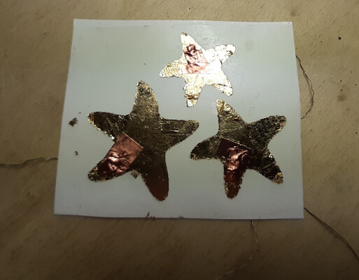 |
The interactive tatoo doesn’t work. It was more of a prototype form to understand how to integrate electronic circuits into a tattoo.
Literature
2016, Kao and al, DuoSkin: rapidly prototyping on-skin user interfaces using skin-friendly materials