Wearables
 This second week on the topic of wearables and e-textiles will provide a more advanced coverage on soft sensors and actuators.
- Document your idea , sketches, references and research
- Learn how to program and ATTiny, add the libraries and links you used for your code
- Create 2 actuator swatches and test them with the Arduino or ATtiny
- Create a swatch using an attiny with one input and one output of your choice, using hard-soft connection solutions and battery
- Document the schematic and the programming code, libraries you had to add and calculations
- Upload a small video of your object working
- EXTRA POINT Integrate it to a project
For me it was a very theorical week.
Actuators support : "El Pulpo"
An actuator is a component of a circuit that moves or controls another part based on input. Some actuators use more current than the Arduino pins can provide. The actuator can be connected to a separate power supply, with a MOSFET (transistor) to switch on and off the current that flows from the power supply to the actuator. The MOSFET is controled by the Arduino card.
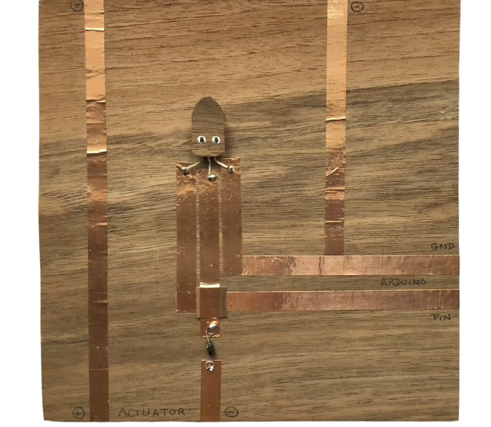
"El Pulpo" MOSFET Circuit
(Pulpo means octopus in spanish)
 This circuit simulation is available on Tinkercad
Let's do a card to get the pulpo composants ready for all acutator with less wires in the shield :)
This circuit simulation is available on Tinkercad
Let's do a card to get the pulpo composants ready for all acutator with less wires in the shield :)

* A piece of cardboard or for the luxury version walnut veneer
* Copper tape
* A tiny piece of paper or walnut veneer
* A MOSFET (Power N channel transistor)
* A diode
* Soldering iron
* 9V battery clip if you plan on using a 9V battery as a power supply
* Solder
* Pliers (tinies)
* Apply the copper tape as the scketch shown above.
* Use a piece of paper or wood to insulate the point of intersection of the cooper bands with the iny piece of paper or walnut veneer.
* Use the pliers to bend the legs of the MOSFET far enough apart from each other, the MOSFET could lie flat.
* Solder the MOSFET legs
* Use the pliers to bend the legs of the diode
* Solder the diode legs
Taddam!
Actuators working thanks to "El Pulpo" (or other MOSFET)
Flexinol
Flexinol is a thin alloy of nickel and titanium that contracts when heated than can be use to create movement. I find Jie Qie's flexinol origami crane project suprising and fun.
Electronic Origami Flapping Crane tutorial from Jie Qi
In her project, she put 2 small bands of cooper in the tail as a switch. When you squeeze the tail you close the switch. If the crane is plug to "El Pulpo", this could be automatized by an adaptation of the classic ‘blink’ arduino sketch, with longer on and off times to give the flexinol time to heat and cool.
void setup() {
  //Initialise pin 1 for output
  pinMode(1, OUTPUT);
}

void loop() {
  digitalWrite(1, HIGH);   // contract the flexinol
  delay(8000);                       // during 8 second
  digitalWrite(1, LOW);    // let the flexinol cool
  delay(5000);                       // during 5 seconds
}
Thermochromic ink
Last year, Charlotte Bracho from le Textil lab make a test of thermochromic ink and plug it directly to a battery.
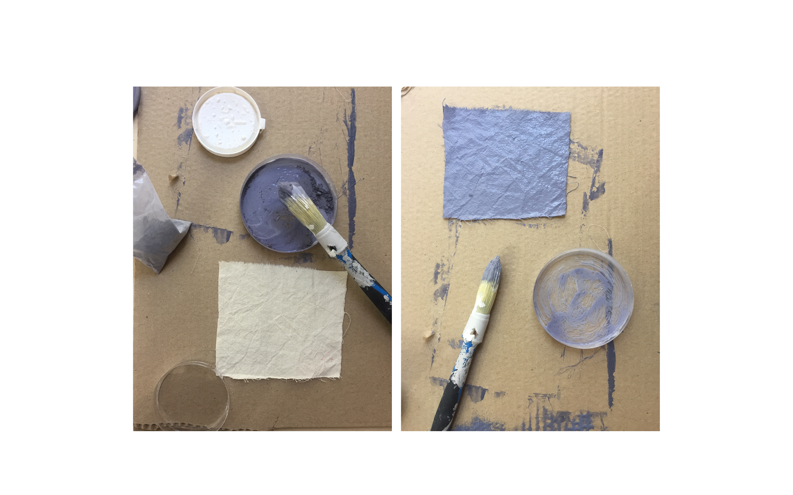
Almost the same code than the crane can be used to test the print sample just getting longer times on and off (15 s and 25 s)
void setup() {
  //Initialise pin 1 for output
  pinMode(1, OUTPUT);
}

void loop() {
  digitalWrite(1, HIGH);   // contract the flexinol
  delay(15000);                       // during 15 second
  digitalWrite(1, LOW);    // let the flexinol cool
  delay(25000);                       // during 25 seconds
}
Code an ATtyni microcontroler
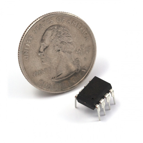
The ATtiny 85 is a microcontroller with 8 Kb of programmable memory from Atmel, it can be programmed with Tiny AVR Programmer or an Arduino using the ISP. The following Arduino commands are supported by a ATtiny85:
- pinMode()
- digitalWrite()
- digitalRead()
- analogRead()
- analogWrite()
- shiftOut()
- pulseIn()
- millis()
- micros()
- delay()
- delayMicroseconds()
Program the ATtiny85 thanks to a Tiny AVR Programmer
Liza Starck give us the links to that tutorial That's the simpler way to can program an ATtyni, and more simple if you are on linux or mac.
unfortanatly I have no AVR Programmer...
Program the ATtiny85 thanks to an Arduino board
I do have an Arduino , let's start !
Preparation of the Arduino board in programmer mode
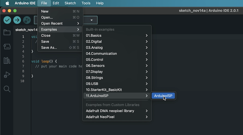
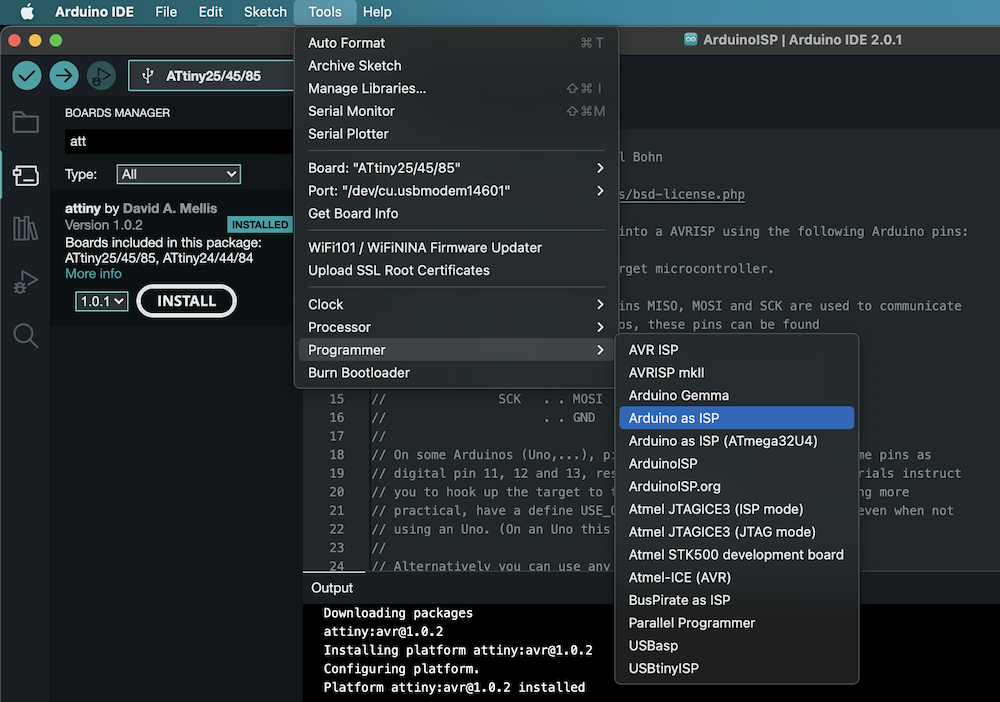
Connect the Arduino to the computer with a Usb cable. Open IDE arduino and in the menu " example " choose " Arduino ISP ".
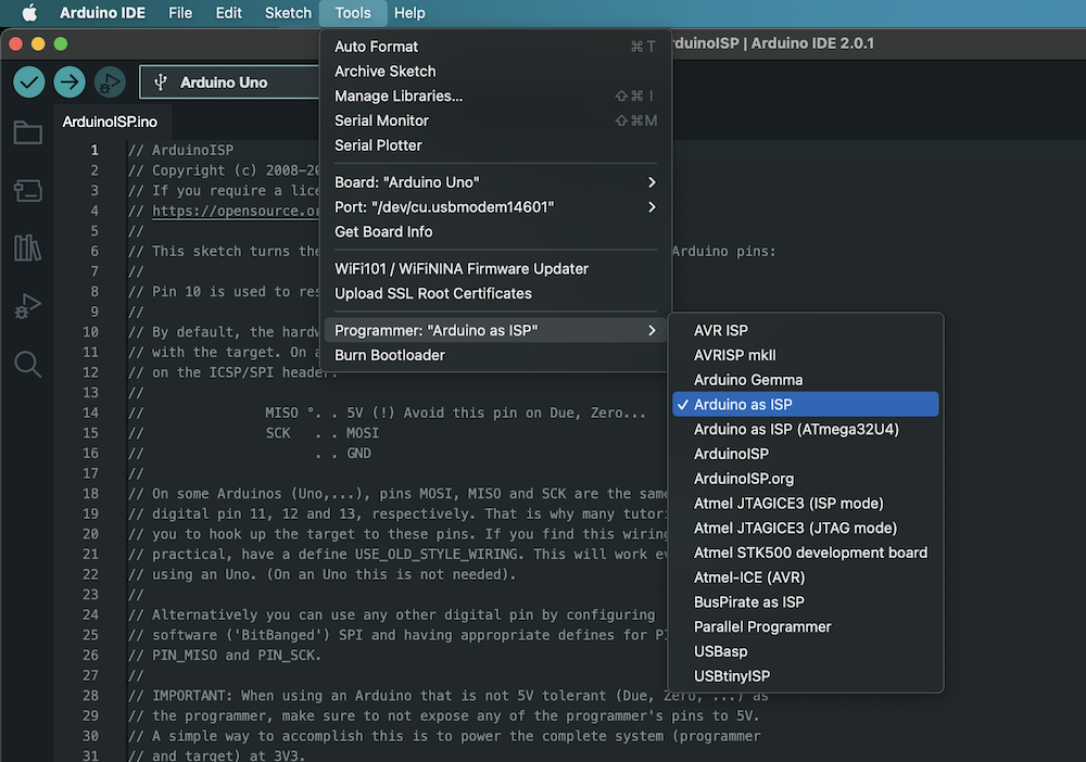
 In "select board" select "Arduino uno", then go to "Tools" > "Programmer" menu, select "Arduino as ISP".
 Upload the program to the board. The Arduino is now a Attiny programer.
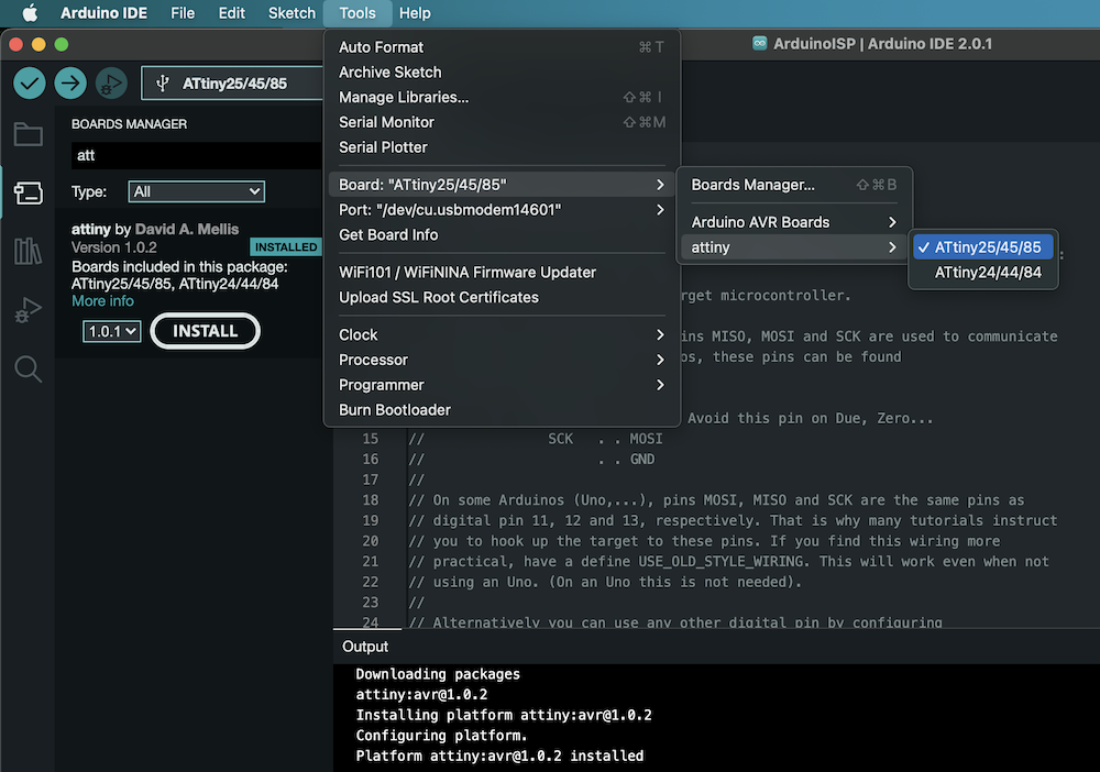
Check the presence of the Attiny files in the IDE > tools > board type.
Upload the program to the board. The Arduino is now a Attiny programer.
Check the presence of the Attiny files in the IDE > tools > board type.
 If there is nothing, you have to install a card manager by going to "Files" > preferences. Add in " Additional board manager URL " paste the following address : https://raw.githubusercontent.com/damellis/attiny/ide-1.6.x-boards-manager/package_damellis_attiny_index.json . Check the path of the sketch location, then click on Ok.
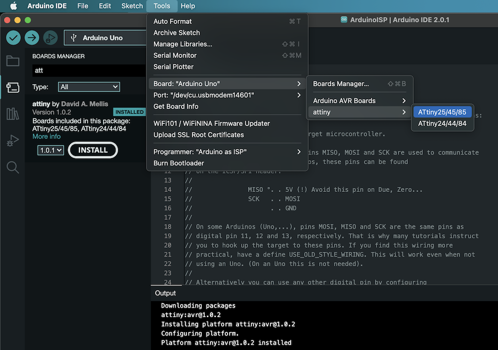
Restart the IDE if necessary to take into account the modifications. Then go to " Tools " > board type > board manager > " Wiring ".
In the window that opens, type " Attiny " then click on Install.
If there is nothing, you have to install a card manager by going to "Files" > preferences. Add in " Additional board manager URL " paste the following address : https://raw.githubusercontent.com/damellis/attiny/ide-1.6.x-boards-manager/package_damellis_attiny_index.json . Check the path of the sketch location, then click on Ok.
Restart the IDE if necessary to take into account the modifications. Then go to " Tools " > board type > board manager > " Wiring ".
In the window that opens, type " Attiny " then click on Install.
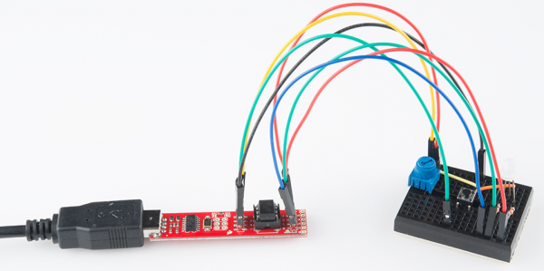
Wiring
This is the wiring for programing ATtiny with Arduino and check it with a blink code.
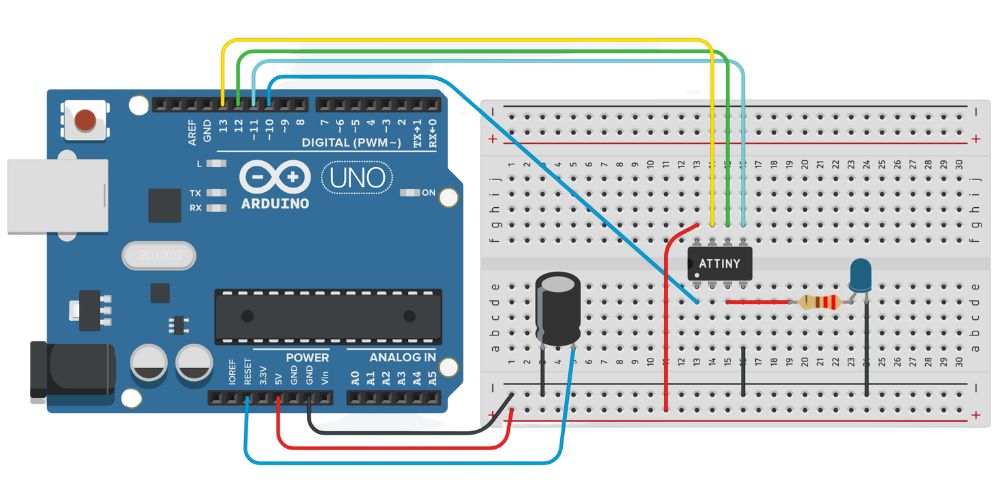 (available on Tinkercad)
What I don't have is a capacitor, I won't take the risk to try without it but I look for the final step.
(available on Tinkercad)
What I don't have is a capacitor, I won't take the risk to try without it but I look for the final step.
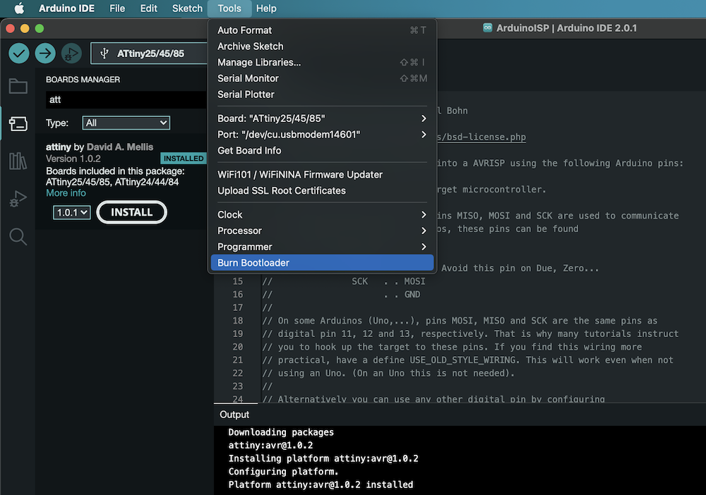
First programming of an ATtiny
When programming a new Attiny chip for the first time, you must click on "Burn bootloader".
 Write this program :
/
Test ATtiny 85 with blinking of a led/

void setup() {
  //Initialise pin 1 for output
  pinMode(1, OUTPUT);
}

void loop() {
  digitalWrite(1, HIGH);   // contract the flexinol
  delay(8000);                       // during 8 second
  digitalWrite(1, LOW);    // let the flexinol cool
  delay(5000);                       // during 5 seconds
}
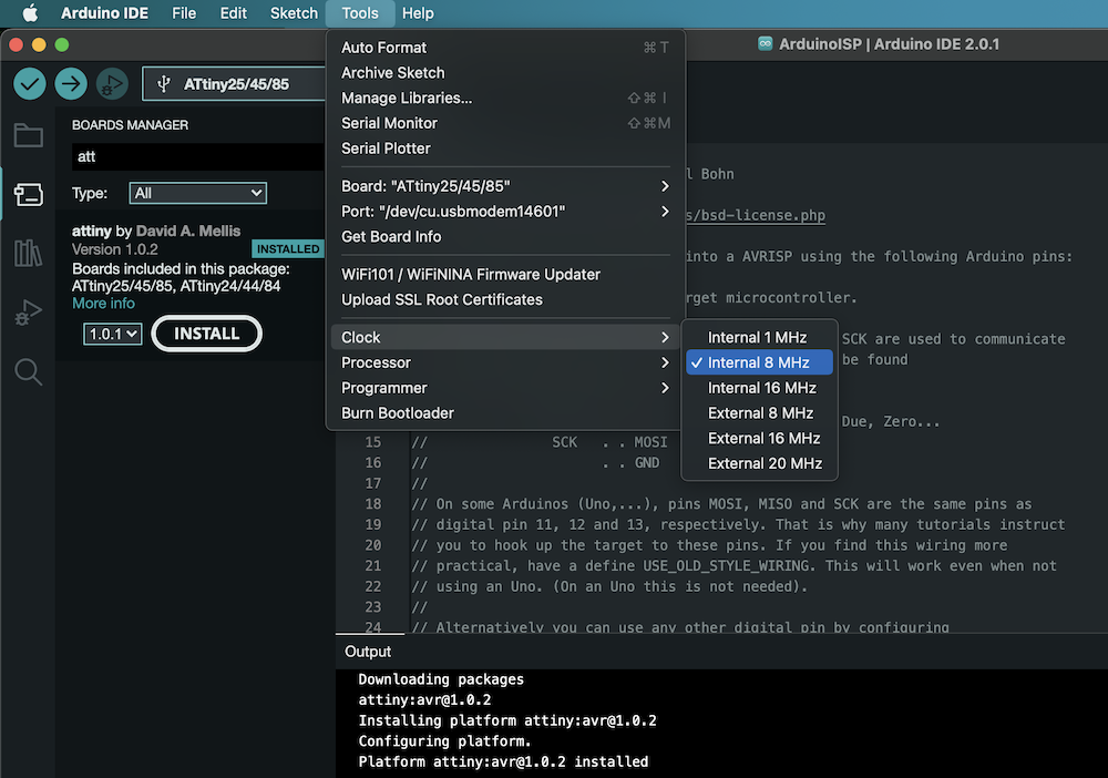
 In clock > choose 8 MHz
 Finally in programmer > choose " Arduino As Isp ".
 Switch your scketch to the ATtiny and check that the LED is flashing. In theory, it's working... If not, well, sorry... Go back to the beggining and check what is missing.
Switch of the TVs with a jacket pocket
TV-B-gone concept
TV-B-Gone allows to turn off almost any TV set within a radius of about 45 meters. It works on a total of 230 shut-off codes - 115 American/Asian and 115 European. A demonstration:
TV-B-Gone is available as a finished product or as a kit collaboration between AdaFruit and Cornfield Electronics.
Turning off the tv's is a militant act
You have probably heard about the horrors brought by FIFA and Qatar for the soccer world cup. To take action here is an action kit (fr) and a page to give a red card to Qatar(fr). One of the action can be to switch off TVs with add and soccer games. The TVGone will do the job perfectly.
Planning to build a wearable TV-B-Gone
I first plan to buy this kit and then discover than Adafruit got a tutorial with a flora and choose that option for its wearability. This is the list of the needed elements to make a TV-B-Gone with a flora card from Adafruit:
*  1 FLORA - Wearable electronic platform: Arduino-compatible
*  2 Super-bright 5mm IR LED
*  2 NPN Bipolar Transistors
*  1 Tactile Switch Button
*  1 Battery Holder (3 x AAA)
*  1 Solid-Core Wire Spool
*  2 Through-Hole Resistors - 100 ohm 5% 1/4
*  heat shrink tubing
*  1 denim jacket
*  conductive embroidery thread
* Solder
* Pliers (tinies)
* wire strippers
* scissors
* a sewing needle
While looking in the code, I read than the flora code comes from a ATtiny code. SO after a full day looking for documentation and Flora tutorail, I decided to jump to an ATtiny circuit wich is cheaper and can be very smaller.
Lets build the ATtiny TV-B-Gone circuit
From these differents tutorials :
- TV-B-Gone clone
- Dirty cheap TV-B-Gone
- $3.50 DIY TV-B-Gone Micro
- TV-B-Gone in a cerales box
- DIY TV-B-Gone SHP
I chose to build this circuit (available on tinkercad) with AAA battery (they are easily rechargeable and the button ones are close to impossible to recycle).
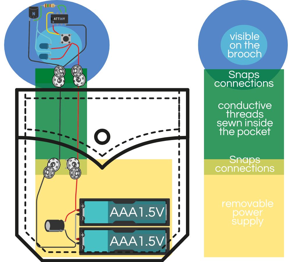 So that the jacket remains washable, only a part of the circuit will be sewn on it. As the weight of the power supply which contains the batteries and the capacitor is consequent, this part will be in the pocket where it will be connected thanks to snaps. The rest of the circuit sewn on a textile brooch will also be removable and fixed and connected by another set of snaps.
*  1 ATTiny 85 A crystal (if it's not "crystal" plan to add a 8MHz resonator)
*  A Arduino uno as ISP and its USB wire
*  2 Super-bright 5mm IR LED
*  1 Tactile Switch Button (or a grumpy, visite my week 5)
*  1 Battery Holder (3 x AAA)
*  1 Resistors - 150 ohm
*  1 22uf capacitor
*  NPN transistor
*  Conductive embroidery thread
*  4 Double metal snaps
*  1 Denim jacket
*  felt and embroidery threads to make a nice brooch
* Solder
* Pliers (tinies)
* Wire strippers
* Scissors
* A sewing needle
* A multimeter
Code
Obviously, it is much easier to flash the ATTiny before sewing. Use the circuit and the programming mode seen above. The code wich is 500 lines, is available in this Adafruit file. As I say before I don't have the capacitor, I didn't want to try without it.
Sewing project
I wanted a loaded brooch so that the LEDs as well as the button are not too visible while keeping the button accessible and the LEDs effective (the lighting of the IR LEDs is not visible to the human eye, they can be see as big beads)
Because I don't have half of the materials needed (not even a jacket with pockets on the chest...) here is my sketch.