2. Digital bodies
Research & Ideation
I was already familiar with the digital design and fabrication tools of this week's assignment. Therefore, I wanted challenge myself in making a mechanically moving model as well as making use of the potential of material that I was going to use, plain old corrugated cardboard.
I am very interested in the added time dimension of an object, how things can change, ambiguous and ephemeral aspect of perception.
Two people, a man and a woman, are enclosed in a box. The box is their "home" where they form a unit together. They are also facing opposite directions, united but also individual. When the box opens they are facing the same direction. They face the world together.
References & Inspiration
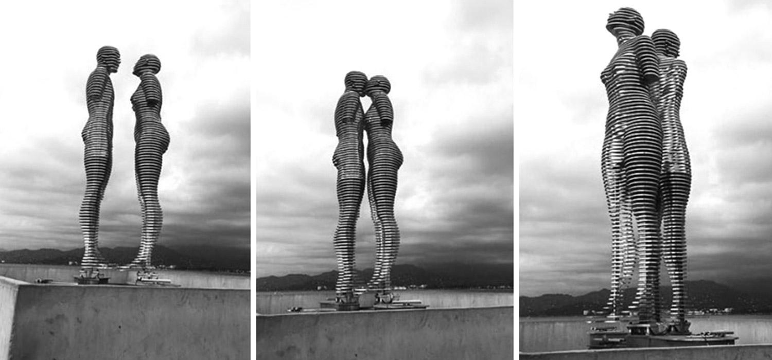
Title: Man and Woman / Creator: Tamara Kvesitadze / Date Created: 2012 / Location: Tbilisi, Georgia / Physical Dimensions: 210x220x100 cm / Type: Kinetic sculpture / Publisher: Georgian State Museum of Theatre, Music, Cinema and Choreography - Art Palace / External Link / Medium: Aluminium, mechanics
Description
"What Tamara wants to say artistically, she usually says with the human form. Sculpture "MAN and WOMAN" is an interpenetration of two bodies, masculine and feminine. It is a never-ending story of love and separation, of joy and of sadness, of pleasure and suffering. [...]" read more
Tools
3D scanning
- Kinect with Scanect software
- Sense with 3D Systems Sense software (a brief tutorial below)
3D modeling and cut file preparation
- MakeHuman
- Rhinoceros and Grasshopper
- Slicer for Fusion 360
Laser cutting
- BRM 1612 laser cutter with Lightburn software (a brief tutorial below)
Scanning with Sense and 3D Systems Sense software
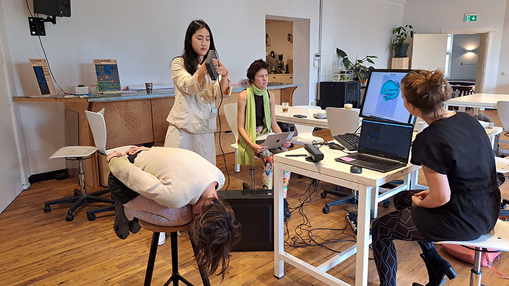
In the lab, we have both Kinect and Sense scanners. We used both of them in the tutorials.
The 3D scanner we have at the Fablab is Sense 1 from 3D Systems. You will need the software 3D Systems Sense to accompany the scanner. The Software and the user guide can be found on their website.
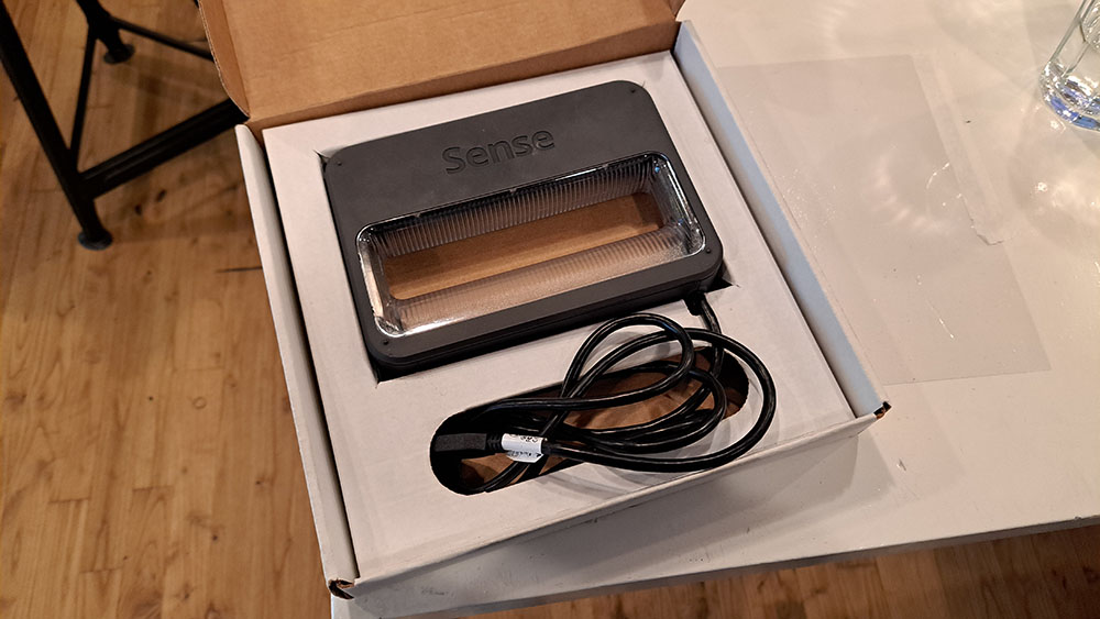
Plug Sense to your computer via USB-port.
Open the Sense software.
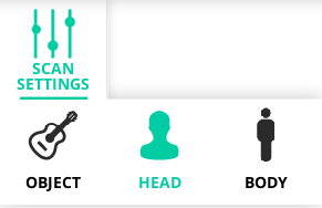
Go to SCAN SETTINGS > HEAD
Press SCAN
While scanning, check your computer screen. Green overlay on the model indicates the scanning is going fine, continue; red overlay indicates the scanner lost reference, so go back to a point which the scanner can recognize and continue from there.
When the scan is finished, press PAUSE and then FINISH
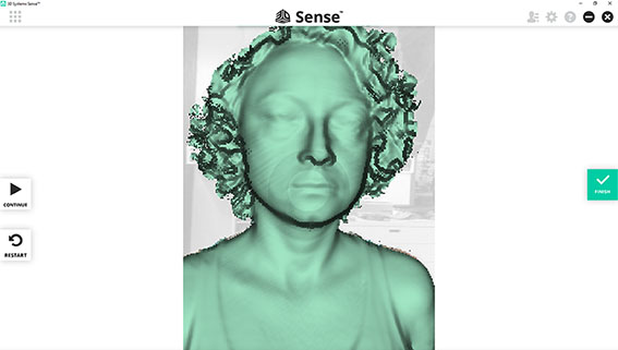
Rotate and check the model. You can adjust your model with TRIM and ERASE
Once you are satisfied with the model, Press SOLIDIFY. Solidify creates a 3d printable model.
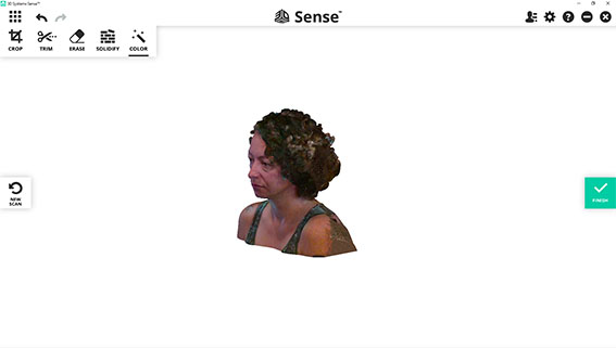
Press FINISH when you are done and SAVE your file for future use.
EXPORT your model as .obj file. You can use this file in Rhinoceros or other modeling softwares.
BRM 1612 laser cutter with Lightburn software
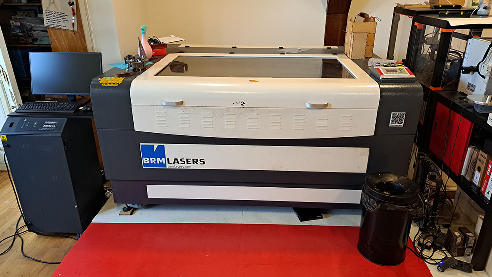
We have a BRM Original 1612 lasercutter at the lab, which runs with Lightburn software. The max. work area of the lasercutter is 1537*1137 mm.
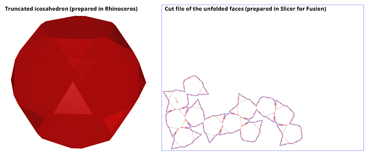
For this tutorial, I modelled a truncated icosahedron in Rhinoceros, whose native file type extension is 3DM. I exported the model as an STL file. I opened the STL file in Slicer for Fusion and prepared an unfolded cut file with the extension DXF.
Measure the thickness of your material.
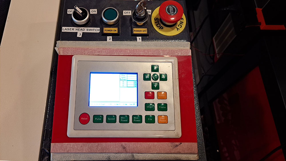
Turn on the lasercutter by turning the key at number 1 from OFF to ON and then pressing button number 2 on the Operation Board.
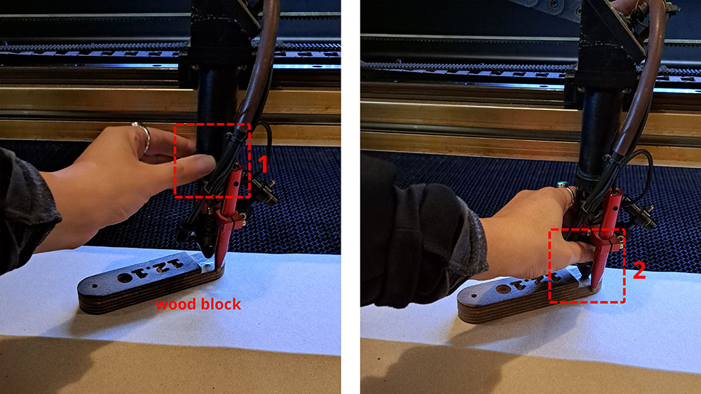
Open the glass front lid with two hands and place your material. Adjust the z-axis of the machine over the material by placing the wooden block on top. Unscew the bracket seen in number 1 and push the laser head down as seen in number 2, then screw the bracket back. Remove the wooden block.
Open your file in Lightburn. Firstly get rid of all the duplicate lines and then close all open shapes.
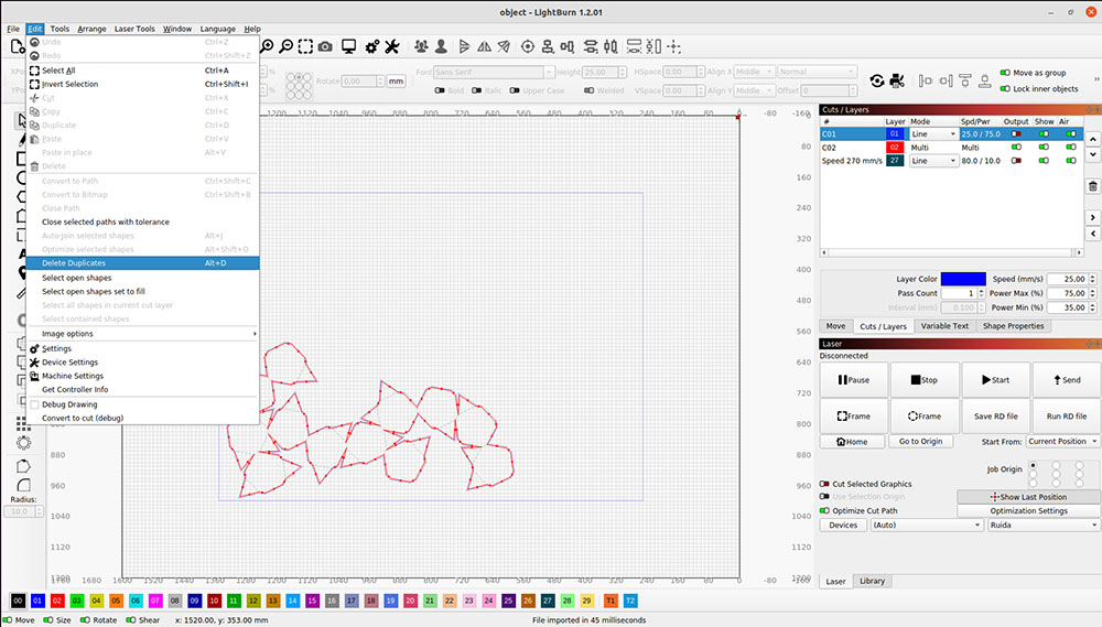
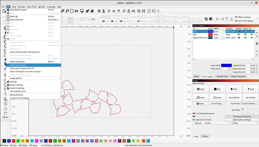
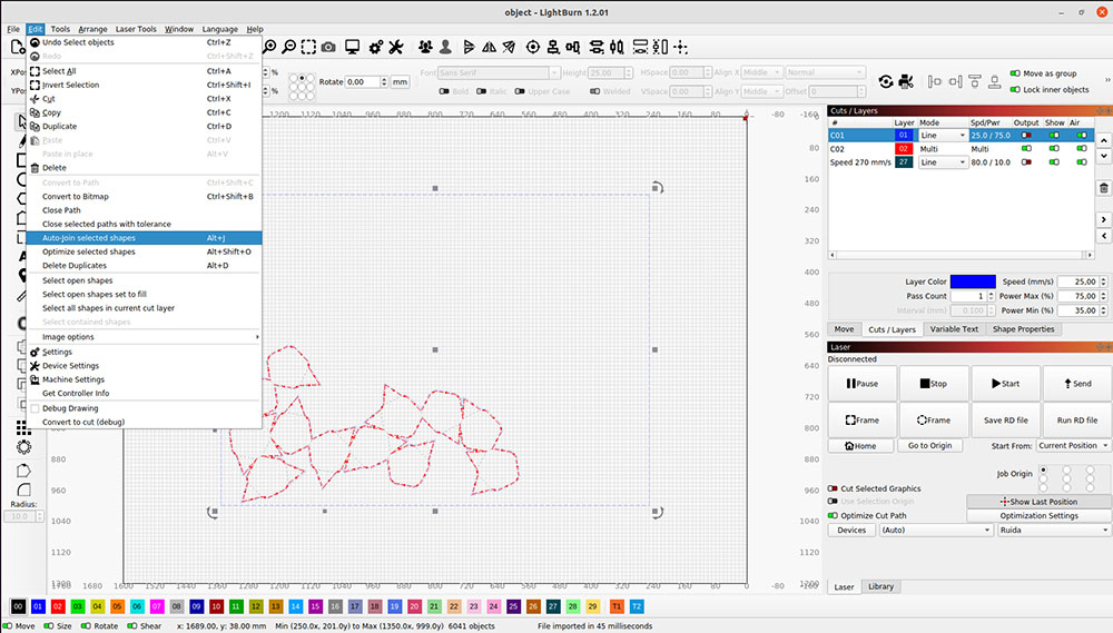
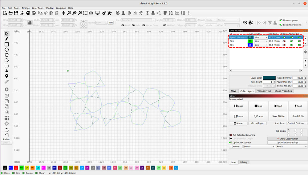
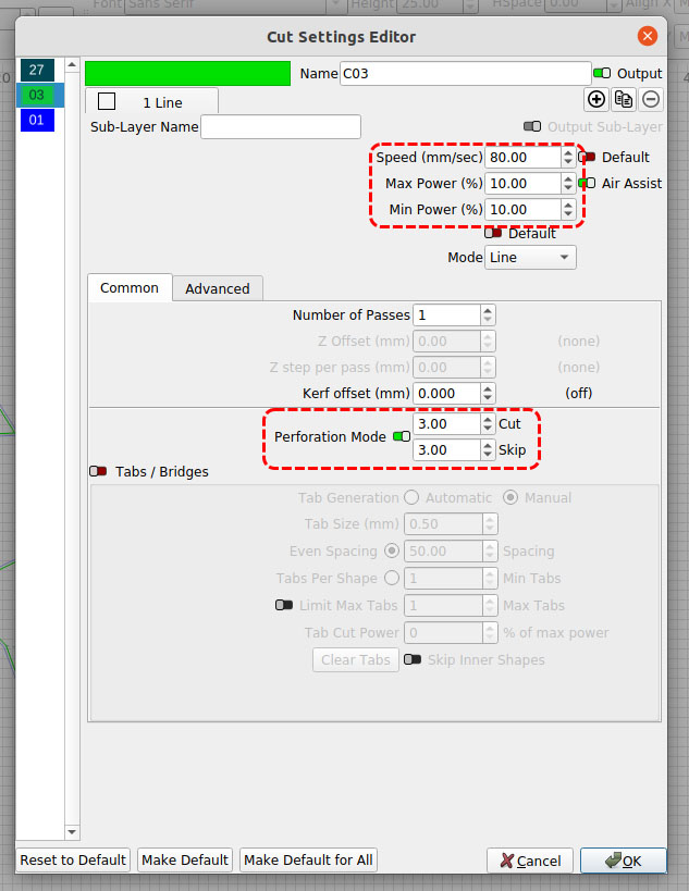
Adjust the speed and power values of each layer by clicking on the spd/pwr values next to the corresponding layer. Make sure to turn on OUTPUT for only the layer you want to cut. You can also make dashed cuts on continuous lines.
Press the LASER HEAD SWITCH on the Operation Board and plug the fume extractor with hepa filter in the socket.
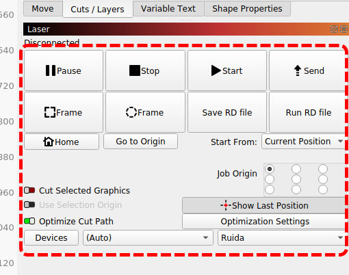 To go to where you want the laser cutting to start, press go to origin and then move the head manually by pressing the arrow buttons on the Operation Board. Hit Rectangular Frame or Circular Frame to see the laserhead draw outline of the job on the material, observe if the outline is within the material surface. Press START to send the cutting job to the machine.
Warning
NEVER LEAVE THE MACHINE UNATTENDED WHILE A JOB IS IN PROGRESS, ALWAYS STAY IN THE RED ZONE!
When the job is finished, wait for extractor to work its magic and suck as much smoke as possible, especially important for plastic-based sheet materials.
Turn the machine off in reverse order of how you opened it.
Tip
- Check if your material is laser cutter friendly.
- Look at the material board right next to the machine and select the material and thickness you will use. If the material or the thickness is not available there, pick the closest one and make an educated guess on power and speed values. Once you enter these values, make a trial cut to see if you can achieve the desired results.
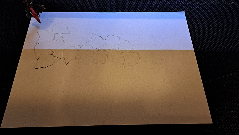
- When you cut outlines of your objects, they can fall on the bed or they can move around in the bed if they are really small. So it is always a good idea to first engrave/etch and then cut.
Process and workflow
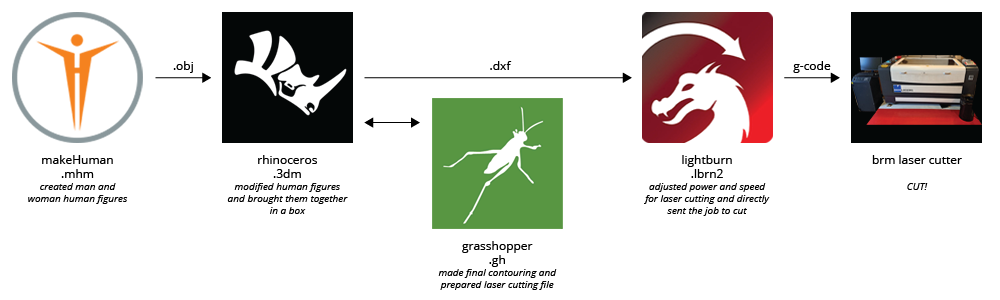
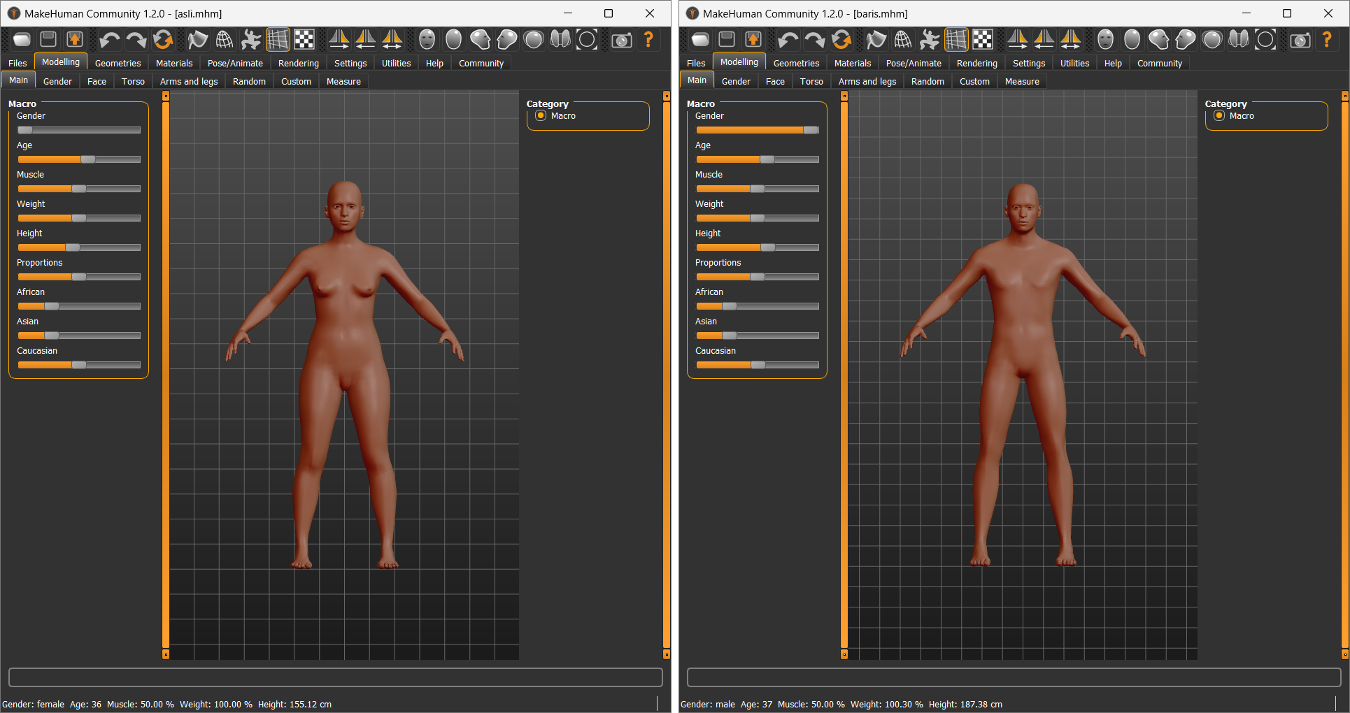
MakeHuman
I created two human figures in MakeHuman. All of their setting are kept at default, only age and height settings were changed to reflect my and my husbands age and height. I am 36 and 1.55m tall, my husband is 37 and 1.88m tall. I always find our height difference quite striking and it is impossible for us to stand back to back and have our heads touch each other or be at the same eye level, unless I am standing on a step. I wanted to be able to have that advantage in the digital world.
Rhinoceros
Imported both figures into Rhinoceros.
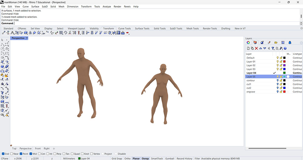
Moved the two bodies back to back [1] and then leveled their head heights [2].
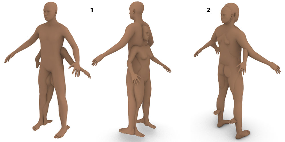
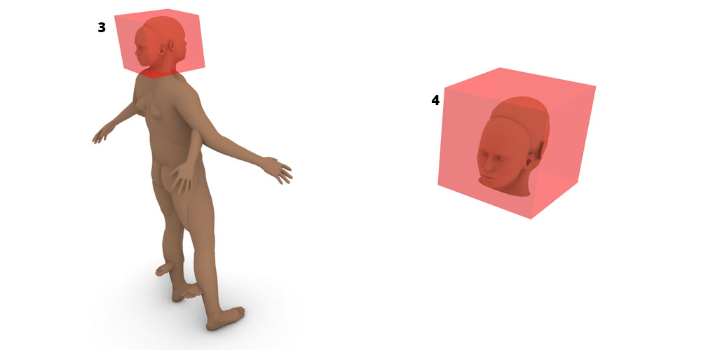
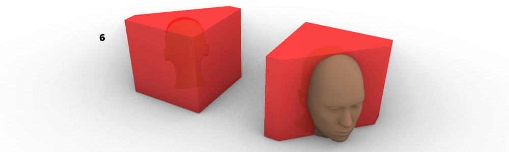
Put a bounding box of 150x150x1500 mm around their heads (this box will be their home) [3] and created a mesh boolean difference to delete the rest of their bodies, leaving only the heads [4].
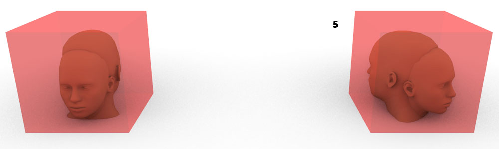
At this point, I had the idea of pivoting the two sides of the box around a hinge axis that is close to one of the corners, so I rotated the heads towards the diagonal [5]. This would allow them to have a better alignment with the rotation.
Divided the box to two parts, since I wanted to slide the man and the woman within each other I assigned opposite parts of the box to each [6].
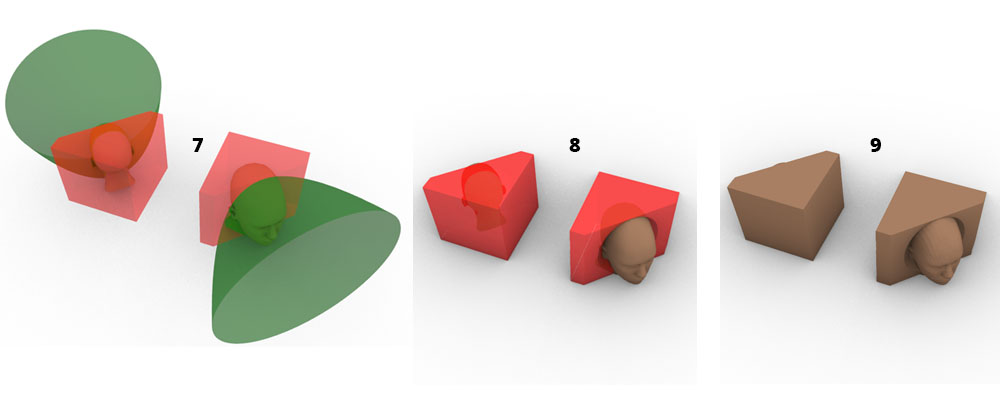
Created paraboloids around the heads to be able to carve the heads out more from their box parts [7]. I split the box parts with the paraboloids and deleted the interiors around the heads [8]. Then, made a boolean union with the the box part and the heads [9].
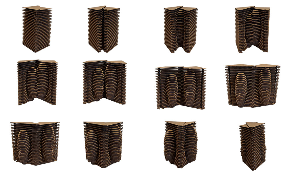
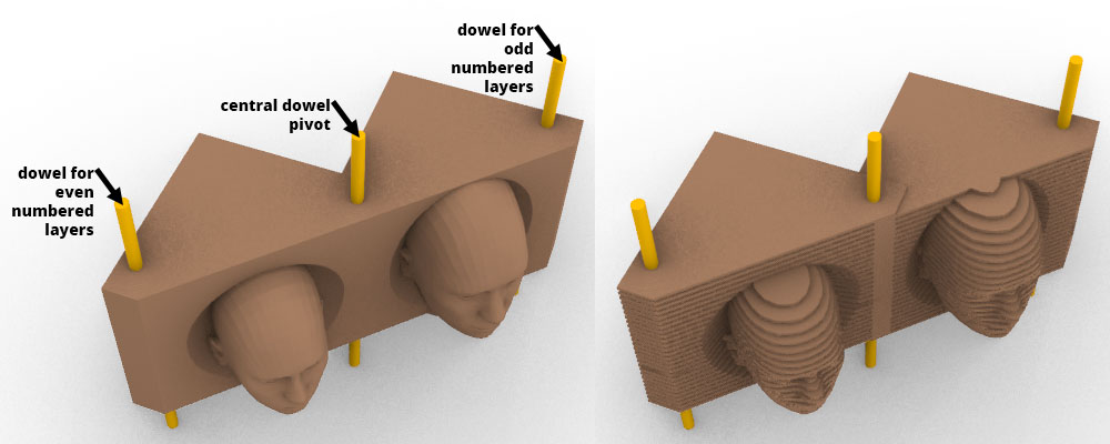
Put three dowels for opening and closing the box. Central dowel is the pivot point and it goes through all the layers. The second dowel goes through only odd-numbered layers and the third one goes through only even-numbered layers. I contoured each part in every 6 mm. The contouring for odd-numbered layers starts from elevation 0 and even-numbered layers starts from elevation 3 mm.
The model
The model is downloadable as an .obj file1 from Sketchfab.
Grasshopper
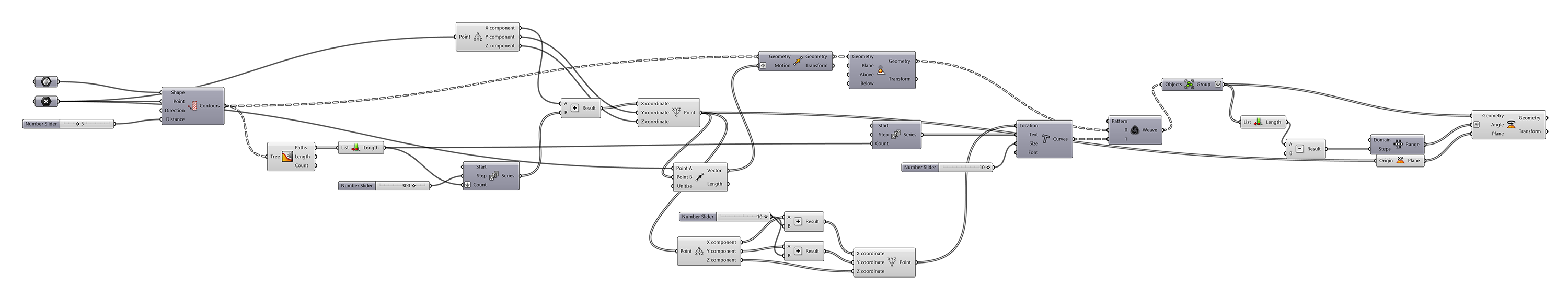
I wrote the grasshopper code2 to easily do slicing, incremental rotation and text placement for tags. You need the accompanying .3dm rhinoceros model3 to work with this grasshopper code. The code takes any BREP and contours it along the Z-axis with given intervals. Moves each contour so that they can lay flat on the XY-plane. Adds a tag to the same location on each slice. Groups the tags with its corresponding contour. Finally, it rotates each section incrementally.
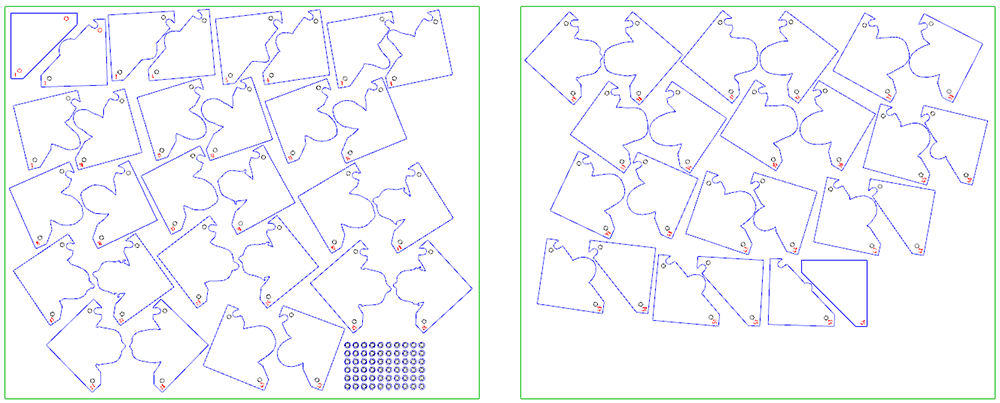
Material - Nesting
The materials:
- Layers: 1115 x 995 x 3 mm corrugated cardboard sheet
- Holding the layers together: 1mm diameter wooden dowels
- Spacers: 3 mm thick acrylic sheet
For this project, I decided to do my own nesting, as it was going to take longer time to nest with grasshopper. So I drew a rectangle of 1115 by 995 mm and put all the sections inside it, as close as possible. I ended up with two cardboards. Then I exported these files as .dxf to move to the next step. For smaller file size in the repo, I share here the .svg file4.
Assembly
Used three dowels to hold the layers together, and put spacers inbetween layers so that they can slide effortlessly. The first idea was to have the layers without gaps. However, they do not slide easily because of friction and the edges of the layers catch that crumples them. Now, because of the spacers the faces are stretched unfortunately. But that is a sacrifice I am willing to make.
Final Project

Notes from the classroom
notes from the classroom
Learning outcomes of the week
- The human figure
- 3d scanning
- 3d modeling
- Digital to physical
- Digital fabrication technologies
- Laser cutting
- Lab safety and rules
The body is the canvas of the tailor The digital tailor, the mass customization, personalization is a need from the textile industry. Designing an experience, answering specific needs
From bespoke tailoring to virtual tailoring
Human Proportions The development of the Egyptian Grid System, Greek Kouros, Vitruvian man (Da Vinci), Le Modulor II (Le Corbusier), David (Michaelangelo) -- balance through disfiguration , 4 books on human proportions (Albrecht Durer)
Anthropometry - Data Driven Design
Measurement of the human individual, stereotypes of perfect body are changing
2020s The Augmented Body
transfigureproject.com, Shudu - world's first digital supermodel, thefabricant.com, dressx, NFT fashion - decentraland, metaverse, the next Rembrandt
Old Media, Digitized, Make new forms - Martin Gayford 2012, MIT Technology Review > multidisciplinary collaborations bringing new ways of making
The Medici Effect - term coined by Frans Johansson Innovation occurs at the intersection of multiple fields, disciplines and cultures. Look into the book!
Body being reinvented
- Antony Gormley - "body is not an object but a place"
- Jaume Plensa
- David Cerny - Kafka, Lilith
- Ron Mueck - hyperrealistic but out of scale
- Willy Verginer - realistic figures reacting to contemporary issues
- Gerard, Aron Demetz - traces of the machine is visible - how it is made is revealed
- Anders Krisar
- Sun-Hyuk Kim - network of the body as a tree or nervous system
- Choi Xooang - disturbing
- Katie Grinnan - capturing movement, time
- Claudia Fontes - small clay sculptures
- Digital Bodies 2014 exhibition
- Xavier Veilhan
- Lucy McRae and Bart Hess - body architect
- Studio Dennis Vanderbroeck
How to reintervene on our bodies extension of the body, body modifications
- Old prosthetics
- Rebecca Horn's Finger Gloves - become more than human, detechable prosthetics
- Stelarc - bioengineered body extensions
- Viktoria Modesta - first bionic pop artist, prosthetic leg
3d printed prosthetics - new revolution
- Alt limb pro
Biometric Data body measurements and calculations
FLAT PACK MANNEQUIN IS ENCOURAGED
Fabrication files
-
File: rhinoceros model as .obj ↩
-
File: grasshopper model ↩