5. E-textiles
Research & Ideation
This was a very exciting week for me as I had had some experience with electronics, inputs and outputs but had never worked in the context of textiles. There was a lot to learn about electronics and creating textile samples for electronics: circuit components, using a multimeter, conductive textile materials (such as threads, fabrics and velostat), creating connectivity, using a knitting machine. I had a chance to refresh (or learn again because mostly it was gone) my highschool physics lessons about circuits and electricity.
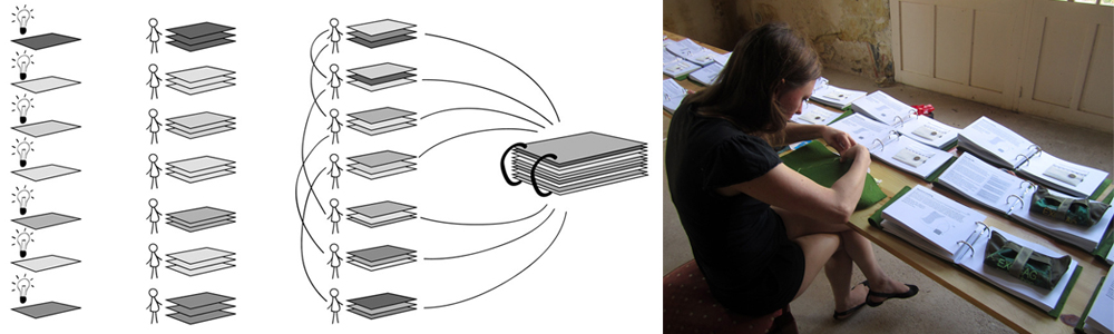
My project this week was the start of a modular swatch library which I can use and expand in the future too.
References & Inspiration
I was very much inspired by æ sensation map by Ieva Maria Dautartaite, created as her final project of Fabricademy in 2023.
Another inspiration was contemporary craft book by Astrid van Roij-Lubsen, created as her final project of Fabacademy in 2012.
I also liked the concept behind the Swatch Exchange. Creating a unique etextile swatch for everyone involved in the exchange and in return getting a sample from everyone else, thus creating a swatch library.
Tools
Textiles and other materials:
- Conductive thread
- Non-conductive thread
- Non-conductive yarn
- Embroidery fabric (cotton)
- Felt
- Conductive fabric
- Copper tape (sticky on one side)
- Fusing fabric
- Conductive snap button
- Conductive button
- Conductive beads
Tools:
- Crochet hook
- Needles of various sizes and tips (according to thread diameter and fabric that it goes through)
- Scissors (one for cutting conductive materials and one for cutting the rest)
- Utility knife
- Cutting mat
- Metal ruler
- Pen
- Pom-pom maker
Electronics:
- Multimeter
- LED (various colors)
- Resistors
- Arduino uno board
- Alligator clips
- Jumper wires
Process and workflow
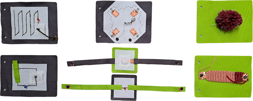
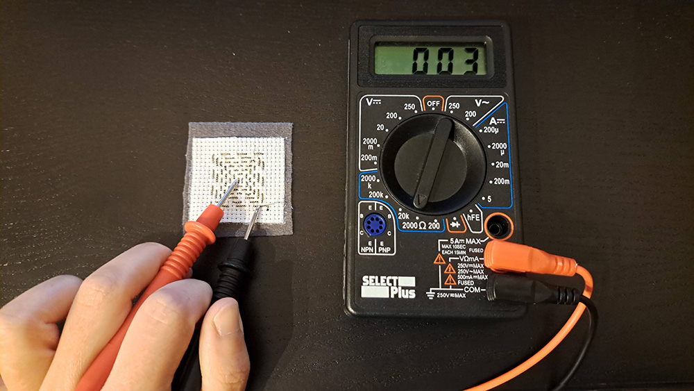
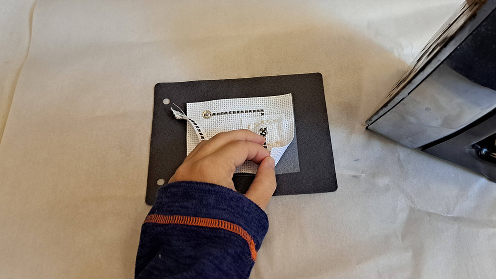
From the beginning, I had the idea of creating a catalog that I can expand in the future. To create a visual continuity, I used felt as my background material and embroidery cotton fabric as my medium on which I created my circuits. I used fusing fabric to bring together the felt and the embroidered circuits. Before jumping into this idea, I made a small sample and tested the resistance change (if there was any) before and after fusing the two fabrics together with a multimeter. Luckily, there was no change in resistance, so I went ahead with creating my swatches.
Digital Sensor
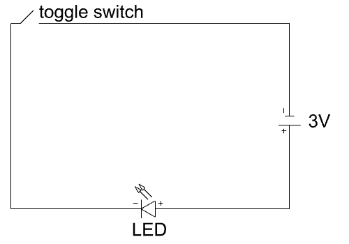
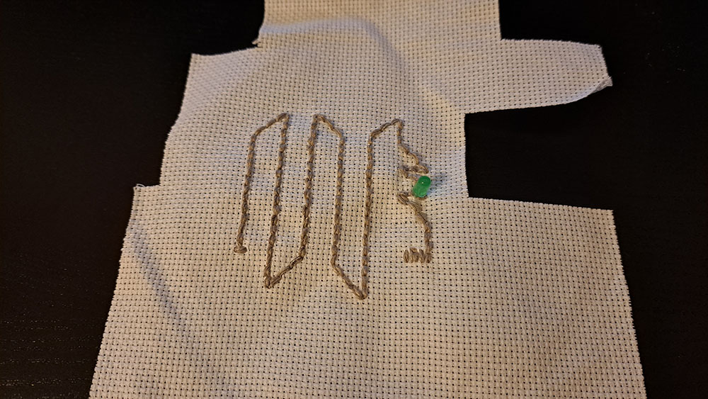
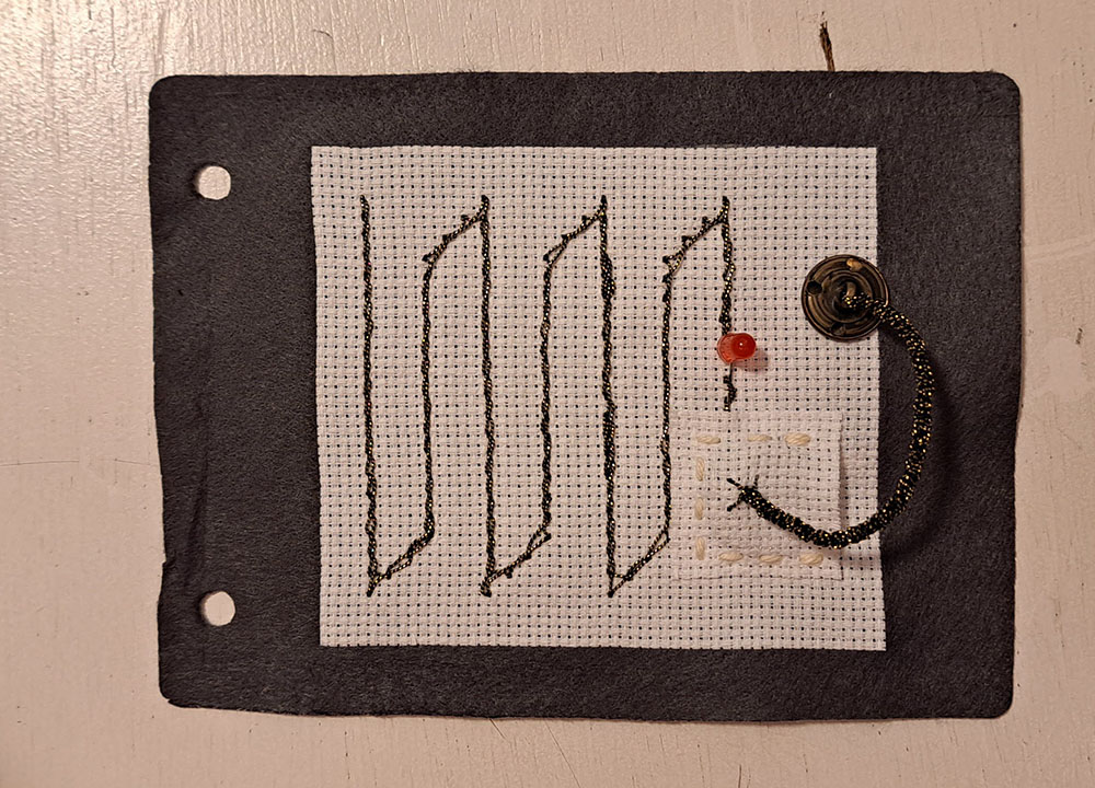
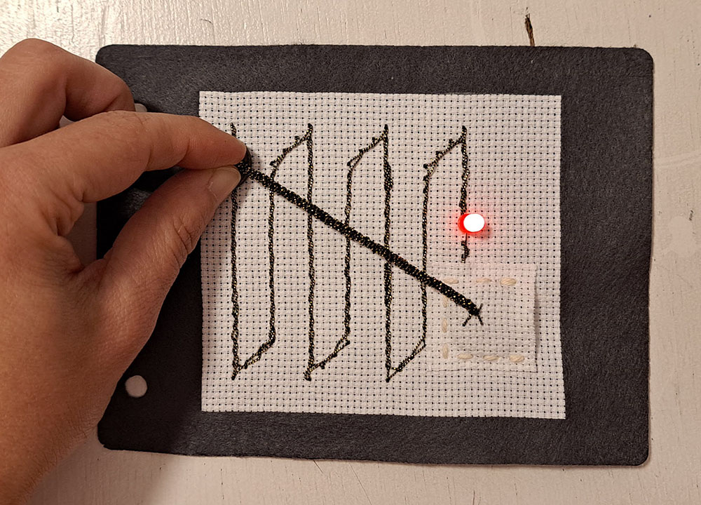
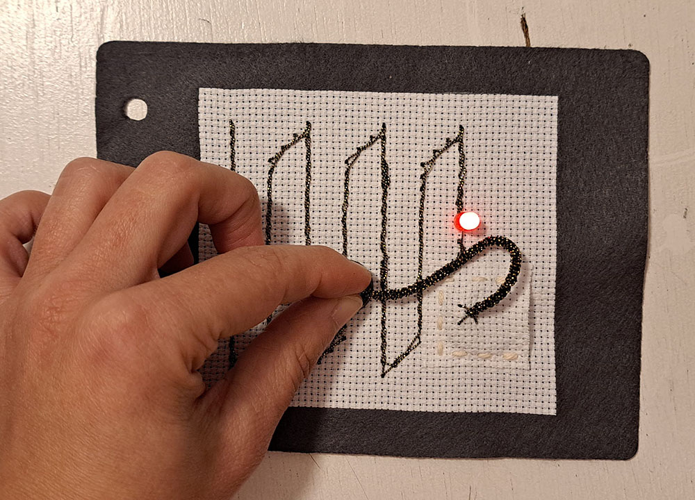
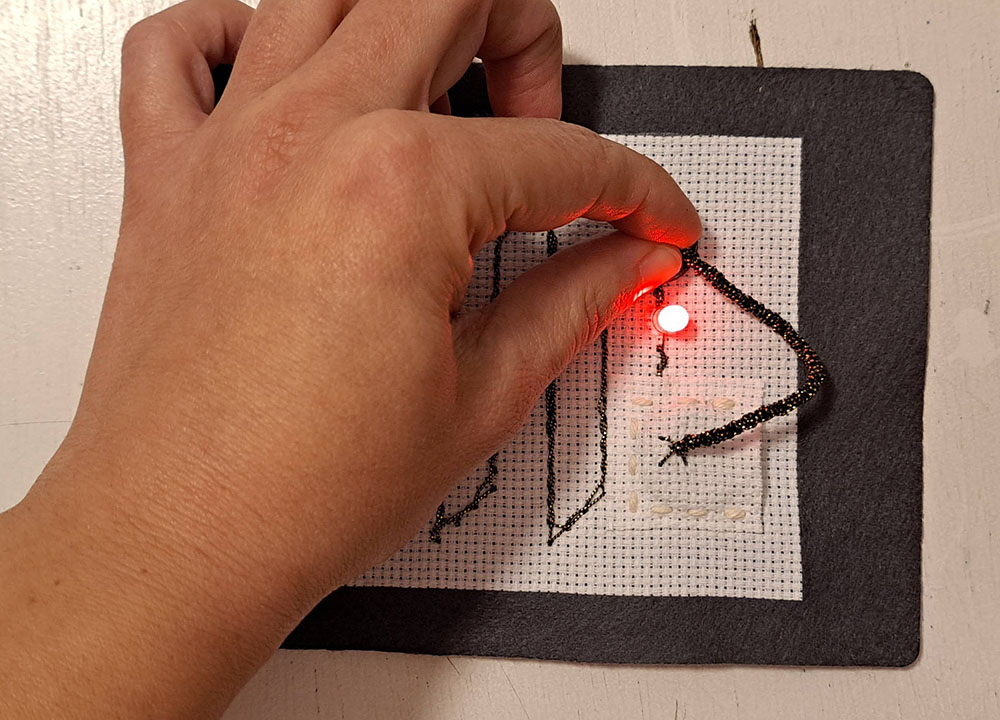
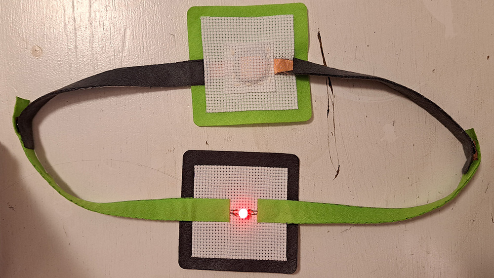
Digital sensors give simple feedback with two possible outcomes: ON/OFF, 1/0. I started with this simple sensor type, a digital toggle sensor with a snap button. I embroidered the circuit on embroidery fabric with a conductive thread using cross stitch technique. The snap button here acts as the toggle switch of the circuit. When it is not buttoned, the circuit is open, therefore the LED does not light up. When it is snapped into place, the circuit is closed, therefore the LED lights up.
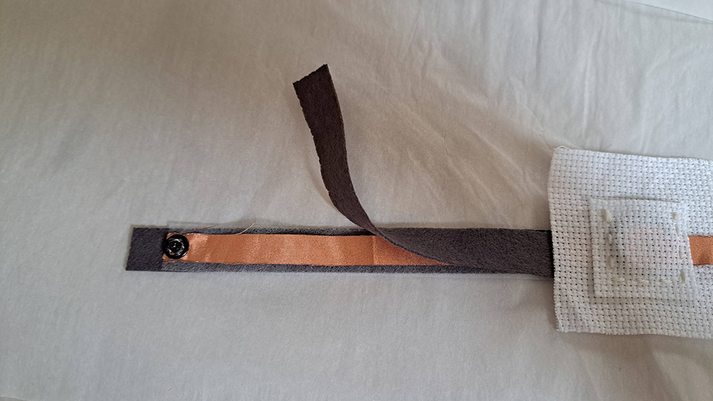
Analog Sensor
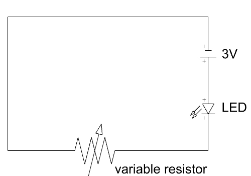
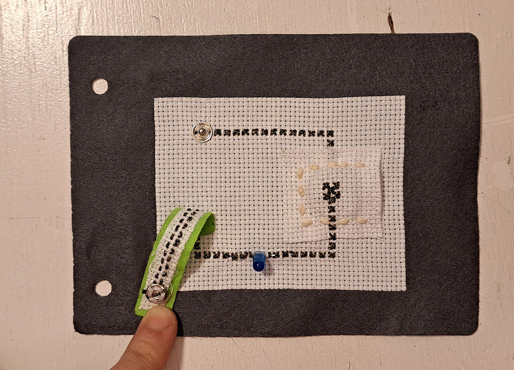
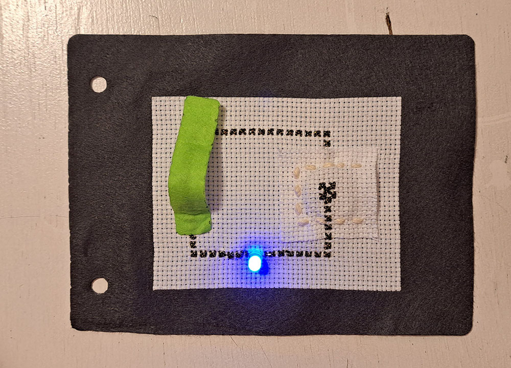
Analog sensors give variable resistance reads. Resistance in a circuit is important because it affects the voltage that runs in the circuit. There are three ways to manipulate resistance: distance (when distance increases resistance increases too), contact (when contact increases resistance decreases) and surface (when surface increases resistance decreases). I wanted to test the first method of manipulating resistance, by distance. When the button moves along the trace towards the LED, the resistance decreases due to distance decrease. Therefore LED lights up brighter.
Arduino - measuring resistance
I used the basic code Michelle Vossen provided to us to check the resistance values of my e-textiles swatches:
/*
Resistance Measurement - www.circuits4you.com
Reads an analog input on pin 0, converts it to resistance, and prints the result to the serial monitor.
Using a 9,5k ohm resistor as known resistor
*/
int ledPin = 5;  // LED connected to digital pin 9

int lowerBoundResistance = 500;
int upperBoundResistance = 1500;

// the setup routine runs once when you press reset:
void setup() {
// initialize serial communication at 9600 bits per second:
Serial.begin(9600);
}

// the loop routine runs over and over again forever:
void loop() {
// read the input on analog pin 0:
int sensorValue = analogRead(A0);

// Convert the analog reading (which goes from 0 - 1023) to a voltage (0 - 5V):
float voltage = sensorValue * (5.0 / 1024.0);

int resistorvalue = 9500;
float I = voltage / resistorvalue;
float VRx = 5 - voltage;
float Rx = VRx / I;
Rx = (5 - voltage) / I;

int mappedValue = map(Rx, lowerBoundResistance, upperBoundResistance, 0, 255);
mappedValue = constrain(mappedValue, 0, 255);

// print out the value you read:
Serial.print("Resistance:");
Serial.print(Rx);
Serial.print(" Ohms");
Serial.print(" and mapped value is ");
Serial.println(mappedValue);
analogWrite(ledPin, mappedValue);
delay(100);
}
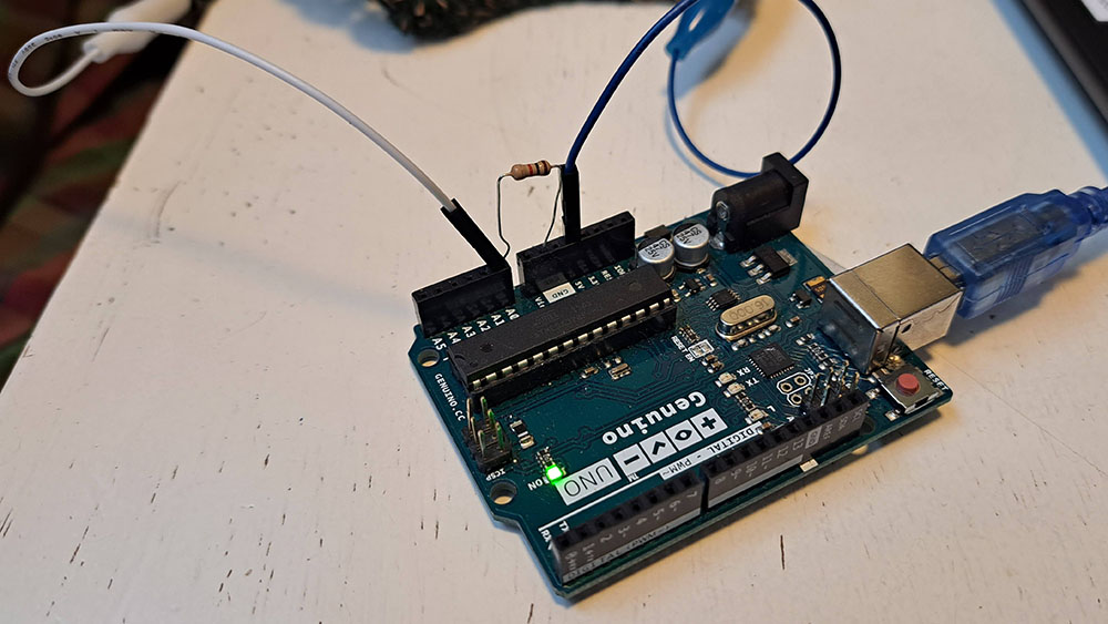
You need to make the following connections to be able to run this code on your Arduino:
- Connect the alligator clip end of one of the jumper wires to the first point where you want to measure the resistance on your circuit and connect the jumper wire end to 5V
- Connect the alligator clipe end of the other jumper wire to second point where you want to measure the resistance and connect the jumper wire end to A0 (this is one of the pins for analog reading)
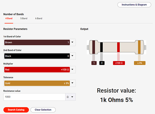
- Connect a 1k Ohms resistor between A0 and GND (Ground) pins. Reading a resistor is HARD, there is no way I can remember each color and their values! If you are like me, you can use this link to make your life easier. The interface is very easy.
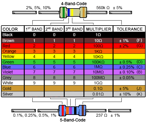
If you want to learn the color codes, be my guest:
Modular Swatches Project
After making the analog and digital sensor swatches I realized that I had to make the battery and LED connections twice for both of them. So the idea popped into my mind: I could create separate battery and LED units and not repeat them again and again on each circuit saving me material and time. I decided to use snap buttons to create the connections between modules.
The battery and the LED module
I replicated the battery pockets of my previous sensors on a separate module. I, once again, understood the importance of using a multimeter. This time, I was able to to realize my mistakes -that are also called short circuits- before spending hours on a module that would not work at the end. After my initial setup (before attaching the felt to the back) I checked the voltage between two ends of my battery module and realized that not much voltage was passing through. Upon inspection, there was a short circuit between the positive and the negative side of the battery. Long story short, CHECK YOUR CIRCUITS EVERY STEP OF THE PROCESS, WITH THE MULTIMETER!!!
The LED module was a no brainer at this point, I had already made 6 LED connections and pretty confident in my LED tracing capabilities.
Hare are the two modules together. As you can see, you can even connect them together:
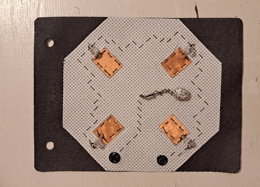
Digital Tilt Sensor module
For the modular project, I made another kind of digital sensor: a tilt sensor. I really like how the underlying grid of the embroidery canvas are very freeing and very referential at the same time. I should continue looking into what else I can do with the patterns on the canvas...
On this swatch, there are snap buttons that await their battery module. This module does not require the LED connection as it has its own built in LEDs:
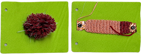
Extra / some analog sensors WIP
These analog sensors are work-in-progress sensors. They both combine conductive threads and non-conductive yarn. The pom-pom sensor has acrylic yarn for non-conductive and the crocheted sensor has cotton yarn for non-conductive. I crocheted with slip-stitch in the back loops technique to have a stretchy textile. This technique is usually used for cuffs and neck parts of sweaters to increase elasticity.
Notes from the Classroom
notes from the classroom
Lecture by Liza Stark
Beginning of e-textiles
- WearComp by Steve Mann (1981-mid 1900s)
- Musical Jacket by Maggie Orth and Rehmi Post (1998)
- How to Get What You Want (website) - sensors out of fabrics - www.kobakant.at/DIY
What is a circuit? - a path for electricity to flow. Electrons move from higher to lower energy or power to ground
Electricity moves counterclockwise in a circuit, from positive to negative
Voltage Volt (V) - electrical pressure or force between two points. Power choice for voltage - batteries, DC power.
Current Amps (I) - Parallel circuits (typically we work with this type) - two different paths, series - one path
Resistance Ohms (R) - Avoid short circuit where electricity travels without resistance.
-
Rule 1 - Electrons are lazy.
-
Rule 2 - Electricity hates waste. All electrical energy in the circuit must be used.
-
Rule 3 - Circuits are system. Different components play a different role.
Fabrics - look at Kobakant for conductive materials. Properties to consider: resistance (check the datasheet, usually measured per square inch), stretchiness (woven, knit, or nonwoven), solderability (always test beforehand!), feel (is this going on the body), substrate+productive process (coated nylon? woven stainless steel?).
Thread and Yarns - Properties to consider: resistance (check the datasheet, usually measured per square inch), solderability (always test beforehand!), thickness (what is the ply? will it fray easily? is it machine sewable?), substrate+productive process (plied stainless steel? coated silver?)
Inks and tapes - CuPro-Cote by LessEMF, Bare Conductive, Circuit Scribe, Copper Tape, ...
Hand Tools - pliers, sharp scissors (separate ), beeswax, crochet hooks, pens, needles, ...
Machine Tools - laser cutter, sewing machine, iron, cricut, embroidery machine, knitting machines
Electronics tools - soldering iron, alligator clips
OPTIONS FOR CREATING TRACES - physical paths of conductive material that electricity moves along in a circuit. Flexibility and aesthetics take new prominence here. Material choices will depend on the use case and goals. Select the fabrication/making technique based on the two before.
- Fabric traces fusing fabric, sew them on.
- Thread traces machine sew
WHAT INPUTS CAN I MAKE?
Input overview - information or data that enters a system, like a button press. digital (switches, on/off, 011011101000), analog (sensors, range of values, 1023, 521, 34).
-
Switches - break in a circuit. DIGITAL
- momentary switches (push buttons) stay open as lons as you hold them by pressing conductive materials into contact.
- toggle switches stay open in one position and closed in the other.
- stroke switches close the circuit by pressing conductive materials into contact.
- tilt switches - a conductive bead or pompom makes contact with conductive fabric patches based on its position.
-
Sensors - ANALOG - using resistance (measured in ohms) to get a broader range of values. The lower the resistance, more current flows. The higher the resistance, less current flows. Factors that affect resistance: distance (resistance increases over distance no matter what the material), contact (some materials are pressure sensitive will decrease in resistance when pressure is applied on them), surface area (increasing the size of the area for electricity to flow will decrease the resistance.)
- Conductive yarn - hard to get your hands on these days
- Velostat (pressure and bend sensor) - carbon impregnated black polyethlene film. Conductivity is not affected by humidity or aging. Cheap.
- Eeontex - not available for sale anymore.
- Polysense - pressure, potentiometer, stretch and bend sensor. in-situ polymerization. dyed on. website
- Pressure sensors by Kobakant
- Bent sensors - resistance decreases as bent and more contact is made.
- Potentiometer - adjust resistance by connecting conductive and resistive material through a wiper at different points in the circuit. The farther away, the more resistance.
- Stretch sensor
Examples: ae sensation map, etextile swatch exchange, flexability, woven sensors (weaving sense at icelandic textile center by zoe romano)
HOW DO I MAKE CONNECTIONS BETWEEN HARD AND SOFT MATERIALS?
- Snap breakout by Kobakant
- Multi-stranded wire by Kobakant
- Second Skin by Malou Beemer
- Touch (and staying in touch) by Anke Loh
-
Flexability
-
Permanent Connections - solder + sew ALWAYS COVER KNOTS AND JOINTS WITH FABRIC OR HOT GLUE, soldering SMD components, solder + sew + crimp beads,
- Detachable Connections - (good for prototyping) SNAPS, etc.
Isolation - prevent shorts! - Always cover knots with fabric or hot glue! - fabric (with iron-on adhesive, 3M electrical cloth tape), paracord, beads, ...
ARDUINO
- Microcontrollers: Input, Process, Output, Feedback
- LilyPad (sewable arduino board), Adafruit Flora, Teensy LC (hard to sew but handy)
- PINs - A pin is how inputs and outputs communicate with arduino
-
The IDE - programming
- Anything in the setup() happens once
- Anything in the loop() happens forever
ELECTRONICS AND SENSORS Tutorial by EMMA PARESCHI
Standard elements of interactive projects - Power, Input device (collect data) -generates signal-, Output device (change the space) -uses signal-, mictrocontroller (process and control).
Dynamic electricity - also known as electric current. current = flow of electric charges (electronics). Unit of measure Amperes (A) ("Amps")
1A = 6241.... electrons
Most probably you won't work with Amperes but with lower amount. Ex. LED: 0,005 / 0,020 Ampere
Annotation note:
- 1 milliAmpere (mA) = 0,001A
- 5mA = 0,005A
- 20mA = 0,020A
- 350mA = 0,35A
Power Source - Voltage
- The power source has always two terminals: Positive terminal (VCC), Negative terminal (GND)
- It has an orientation.
- Tha capability to move the charges between two points is called Voltage.
- Unit of measure: Volt (V)
MULTIMETER
- Black lead -> port COM
- Red lead -> port V (to measure voltage)
Turn the knob toward Voltage values. The numbers on the multimeter indicate the max measurable value. If what you are measuring is over the max then the multimeter reads 1 or OL (overload)
CIRCUIT
A circuit is a system in which we use electricity energy. A circuit is a close loop in which electrons can travel in. You need -> source of electrons (power source - battery), material to let the electrons flow (traces - wire), something to avoid short circuit (load - resistor).
Resistor Purpose is to impede a flow of current and impose a voltage reduction. Two wires or conductors attached at opposite ends or sides of a relatively poor electrical conductor. It has two sides, it doesn't matter the orientation.
Through hole technology (THT), Surface mounted technology (SMT or SMD).
The resistance of resistor is measured in Ohms, universally represented by Ω.
Notation of Ohm: kiloOhm
- kiloOhm: kΩ
- 1kΩ = 1*103 Ω = 100 Ω
The simplest circuit
- Voltage: is the different
- Current:
- Resistence:
OHM'S LAW
Defines the relation between voltage, current and resistor:
V = I * R = IR
- Higher is the Resistor -> Lower is the current
- Lower is the Resistor -> Higher is the current
LED (light Emitting Diode)
- Anode (+) - long leg
- Cathode (-) - short leg
Orientation: Current must flow from long leg to the short leg. _ Forward voltage: the voltage across the LED is specified for the component. _Forward current: it emits light only if the current is withing the range.
Vf = 2V/3V If = 0,005 ...
R = (Vcc-Vf)/If
SENSORS Interaction with sensors changes a change in voltage.
- Digital - they open or close - momentary, toggle, tilt, stroke switch
To use the switch as sensor you have to use an extra resistor. The name of this resistor is Pull-up resistor. Arduino will measure the change in voltage.
- Analog - Interaction with the sensor, you change the resistance , so you change the current. They have two terminals. Ex: pressure sensor, stretch sensor.
Velostat - piezoresistive material