Code + Components
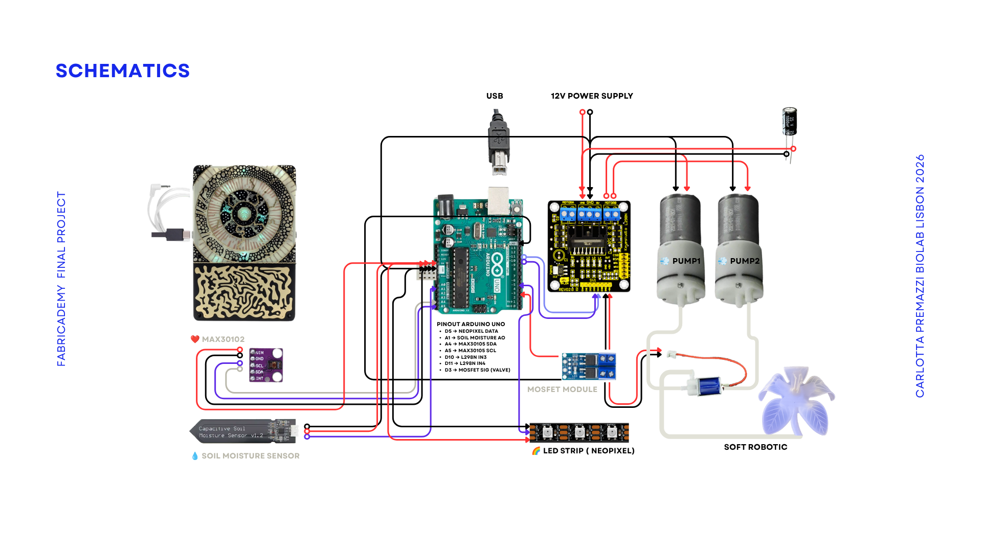 Radical EcoSystem Schematics. Carlotta Premazzi 2026
Hardware & Components
- Arduino UNO
- MAX30102 heart rate sensor
- Capacitative moisture sensor (analog)
- NeoPixel LED strip (WS2812B)
- L298N motor driver
- MOSFET module
- 2x 12V DC mini air pumps
- air valve (for soft robotic flower)
- Soft robotic pneumatic flower
- 12V power supply
- 1000 capacitor
- USB cable
- Breadboard
- Jumper wires
- Air tubing
Software
- Arduino IDE
- Pure Data/Web Audio
- TouchDesigner
Control Unit and Electronic Integration
The control unit is located at the base of the installation and integrates the electronic system, pneumatic infrastructure, and signal routing. It acts as the interface between biological inputs, computational processes, and physical actuation.
Laser-Cut Acrylic Enclosure
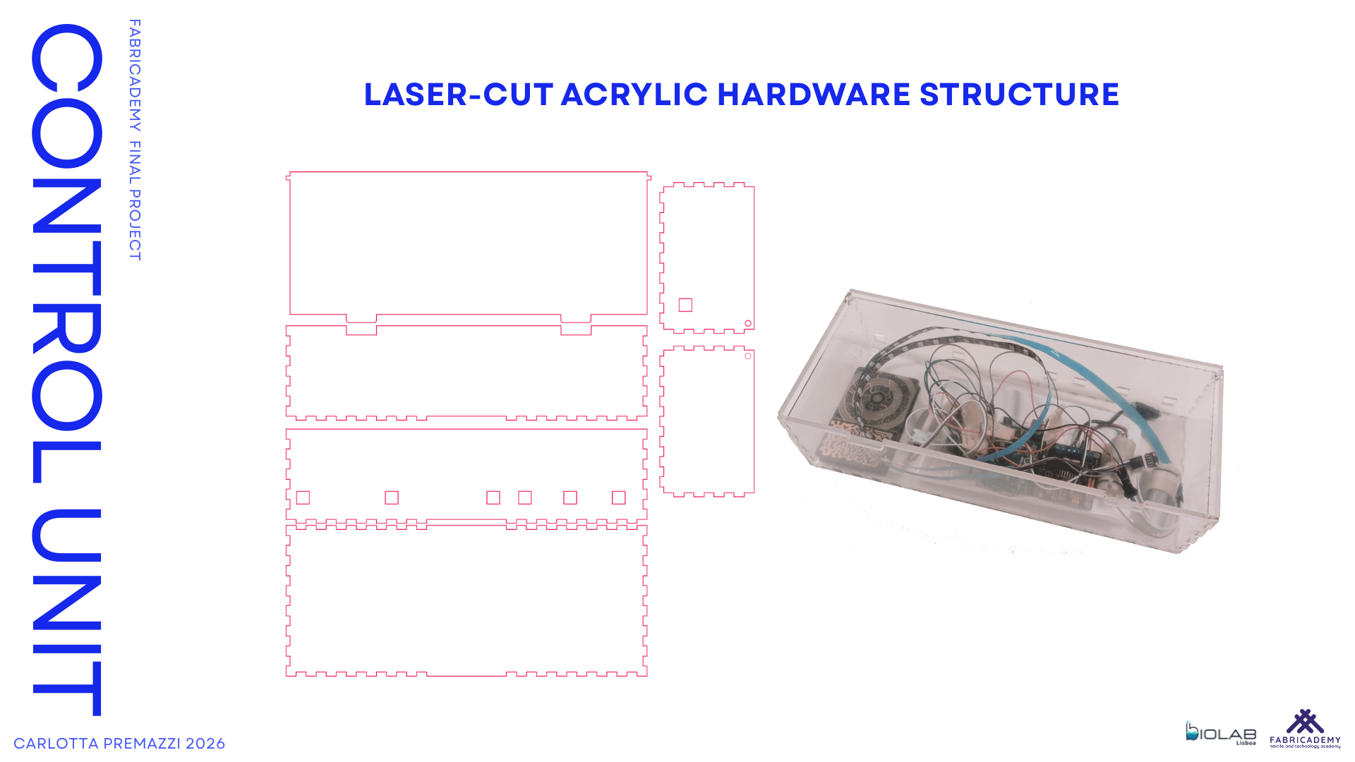
Fabricated at FabLab Lisbon using a GCC LaserPro Spirit LS laser cutter
Material: 4 mm transparent acrylic (550 × 550 mm sheet)
Kerf: ~0.15 mm (experimentally calibrated)
The enclosure houses all electronic components and pneumatic connections, providing both protection and structural organization.
Design Considerations
- Separation between 5V logic and 12V power lines
- Dedicated routing paths for air tubes
- Ventilation openings for heat dissipation
- Press-fit joints calibrated through kerf compensation
The structure was designed using finger-joint connections, allowing panels to interlock without adhesives while maintaining rigidity.
Kerf compensation was applied to the male joints by reducing their width by approximately 0.15 mm. This ensured accurate slot fitting and enabled a tight press-fit assembly.
Joint tolerance was refined through iterative testing, resulting in a structure that can be assembled manually and easily opened for maintenance.
Electronic System Integration
Inside the enclosure, an Arduino microcontroller manages communication between sensors, actuators, and computer-based software.
The system collects data from:
- a soil moisture sensor (environmental input)
- the Pocket Scion device (plant bioelectrical signals)
These signals are transmitted to the computational environment, where they are processed and translated into system behaviour.
At the same time, the control unit drives the pneumatic pumps and organizes all wiring and air tubing required for the installation.
All components are contained within the enclosure, ensuring clarity, accessibility, and protection.
The transparency of the acrylic reveals the internal technological infrastructure, reinforcing the hybrid aesthetic of the project, where biological signals interact with exposed technological systems.
Arduino UNO — Pin Mapping
| Pin | Component | Function |
|---|---|---|
| A1 | Soil Moisture Sensor | Analog input (0–1023) |
| A4 | MAX30102 (SDA) | I2C data line |
| A5 | MAX30102 (SCL) | I2C clock line |
| D3 | MOSFET Module | Air valve control (digital) |
| D5 | NeoPixel LED Strip | Data signal (WS2812B) |
| D10 | L298N (IN3) | Pump IN / Inflate (PWM) |
| D11 | L298N (IN4) | Pump OUT / Deflate (PWM) |
| 5V | Sensors + LEDs | Power supply |
| GND | Common Ground | Shared reference |
| 12V | Pumps (via L298N) | External power supply |
Data Streams
The system uses two parallel data streams:
| Source | Protocol | Destination | Function |
|---|---|---|---|
| Arduino | Serial, 57600 baud | Pure Data / computer | Sends soil moisture state, heartbeat detection and IR intensity |
| Pocket Scion | OSC | Pure Data / computer | Sends plant bioelectrical activity descriptors for sonic modulation |
Serial Frame (Arduino → Pure Data)
Protocol: Binary Serial
Baud Rate: 57600
Header: 0xC0
Update Rate: ~25 Hz (40 ms)
| Order | Variable | Range | Description |
|---|---|---|---|
| 1 | humidityValue | 0–1023 | Raw soil moisture value |
| 2 | humState | 0–2 | 0=DRY, 1=OK, 2=WET |
| 3 | fingerPresent | 0 / 1 | Heart sensor active detection |
| 4 | irStrength | 0–1023 | Normalized IR intensity |
| 5 | BEAT | 0 / 1 | Beat detection event |
| 6 | beatAvg | 0–220 BPM | Averaged heart rate |
Each value is packed as a 10-bit integer (two 7-bit-safe bytes).
OSC Frame (Pocket Scion → Pure Data)
Protocol: OSC (Open Sound Control)
Transport: Network / USB bridge
Source: Pocket Scion bioelectrical plant signal
| Address | Type | Description |
|---|---|---|
| /min | float | Minimum signal value in window |
| /max | float | Maximum signal value in window |
| /mean | float | Average signal value |
| /delta | float | Instant variation |
| /variance | float | Signal variability |
| /deviation | float | Standard deviation |
These values are mapped in Pure Data to modulate sonic texture and micro-variations.
Data Mapping — Signal to Expression
| Signal Source | Parameter | Affects |
|---|---|---|
| Soil Moisture | humState | Breathing mode (DRY/OK/WET) |
| Soil Moisture | humidityValue | LED chromatic base |
| Heartbeat | BEAT | Pneumatic pressure accent |
| Heartbeat | irStrength / beatAvg | LED wave amplitude |
| Pocket Scion (OSC) | mean / delta / variance | Sonic texture modulation |
| Arduino (Serial) | humState / BEAT | Sound structural parameters |
Coding
Arduino (Control Logic)
The Arduino firmware is structured around three main subsystems:
Sensor acquisition
- analogRead(A1) → soil moisture value (0–1023)
- MAX30105 library → IR signal acquisition
- checkForBeat() → beat detection
- Moving average (RATE_SIZE = 4) → BPM smoothing
- Dynamic normalization → heartNorm (0.0–1.0)
The variable humState is derived from threshold comparison:
- < DRY_THRESHOLD → HUM_DRY
- => WET_THRESHOLD → HUM_WET
- otherwise → HUM_OK
Pneumatic Control (PumpController)
Breathing behavior is implemented through a state-based controller:
pumps.setMode(humState);
Each mode (DRY / OK / WET) corresponds to a dedicated control routine with:
- Different PWM ranges
- Different timing durations
- Different pause structures
Heartbeat modulation is applied only when:
if (fingerPresent && BEAT) pumps.onBeat();
The function onBeat() activates a temporary boost envelope based on:
- Sinusoidal shaping (heartEnvelope01)
- Duration-dependent modulation
- PWM increment proportional to heartNorm
- This boost is added to the current base PWM values without replacing them.
LED Control
LED behavior is handled via the NeoPixel library.
Base color is selected according to humState.
When BEAT == true:
- A red wave is triggered
- Wave amplitude scales with heartNorm
- Position updates at fixed interval (WAVE_STEP_MS)
The LED logic runs independently but relies on the same behavioral variables.
Pure Data Sound Engine
Pure Data receives two types of data:
-
Arduino serial stream
A binary serial frame containing humidity value, humidity state, finger presence, IR strength, beat detection and average BPM. -
6 packed values (10-bit each)
- Header 0xC0
- 57600 baud
- ~25 Hz update rate
These parameters are mapped to:
- State-based structural control
- Beat-triggered events
-
Intensity modulation
-
Pocket Scion OSC stream
Continuous plant bioelectrical descriptors of plant bioelectrical activity: -
/mean
- /delta
- /variance
- /deviation
These values are used as modulation signals for granular texture, filter variation, and micro-parameter fluctuation.
These values are mapped to sonic texture, filter variation, micro-parameter fluctuation, state-based structure and beat-triggered events.